
How to make a part in PTC Creo Parametric
Tags: design and thinkPersonhours: 5
Problem: How to Make a Part in Creo Parametric
PTC Creo Parametric is one of the best software to 3-D model tools that we can print out. I will detail how to create a part in Creo for both our team and any other teams who need help creating a piece. For this demo, Creo Parametric Academic Edition was used along with a pre designed model of the part.
To begin the model, create a new part. Make sure you are making the part in the right dimensions since the 3-D printer needs special requirements. For the 3-D printer that Iron Reign has, we chose to make all of our dimensions in millimeters. You can change this configuration by going into File>Prepare>Model Properties >Units.
Once your program is set to go, go under Model and press Sketch. This will create the base diagram which we will raise to make our part. Once the sketch menu appears, you will have to choose a plane on which we will draw. For this sketch, we will draw from the top plane since we want to raise it from the bottom. To do so, press on the top plane and press sketch. If the view is still in an isometric format, you can change the view by pressing the button indicated in the video.
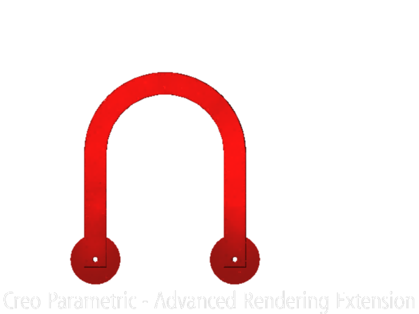
Once the sketch is set up, we need to draw two concentric circles with the right dimensions. To find the dimensions, I refer often to the premade part. Once I have made the system, I set up centerlines vertically to be able to draw better. Next, I cut off the top two parts of the circle since we will put rectangles on them.
Next, select a line chain to draw two sets of rectangles with the bottom edge fused with the half circle. At the end, you should have a U shaped part. Now, we can draw another centerline along where we want the screw holes. After doing so, we can use the circle tool to make two holes in the rectangles.
We now need to extrude this part to the right size. After pressing the extrude took, we can change the size on the arrow. After doing so, we need to place two high radius thin circles on either sides. These are placed as weight pads so that when the part prints, it doesn't curve on the printing bed.
At this point, we can do some optional things to make our part..well lets say prettier. We can use the round tool so the edges look nicer and the screws are easier to place inside. After doing so, we can use the render tool to color all the edges. At the end, you will have a complete part to print
End result:
We hope you learned from this tutorial and are able to apply this to any future parts you make!