
Gripper Physics Diagrams
Tags: innovate, think, and designPersonhours: 1
Task: Describe the physics of the gripper
We always struggle a little with describing our robot to the judges. So, this post will be the third in a series of posts describing the physics of our robot (four if you count the coefficients of friction). First, we have the free body diagrams of the gripper.
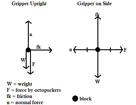
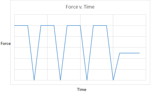
Next, to further describe this, we created an expiriment in which we determined the maximum force one octopucker can apply. We took a traditional octopucker and rotated it so that the arms of the pucker would barely impact the sides of the scale. From that, we applied force until the octopucker moved to the next arm. We then averaged the forces recorded to determine the maximum force an octopucker arm can apply.
Under these circumstances, we recorded an average maximum of 4.125 oz of force, which translates to 1.147 N. This translates to an increase in the normal force of +6.882 N. This, in turn, increases the frictional force of the internal lift by fk=uN, where u is the coefficient of friction of the internal lift to the glyph. fk=1.96*6.882=13.489N. So, the simple creation of modified intake octopuckers allowed us to increase the frictional force by +13.489N, which allows our internal lift system to operate.
Force exerted by the octopuckers vs time
Next Steps
On Saturday, we will continue this series of posts, finding the series of constants in infopost #2.