
Linear Slide Lift
Tags: design and thinkPersonhours: 4
Task: Design a lift for MiniChassis
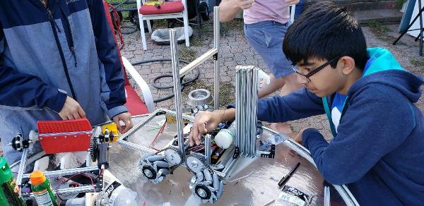
For extension both into the crater and lifting our robot up to the crater we have decided test a linear slide system. We plan to utilize linear slide system for both vertical and horizontal extension on MiniMech.
Horizontal Extension Goals
- Long Enough to reach Crater from distance
- We need to determine how many stages we need
Vertical Extension Goals
- Long Enough to reach lander
- Strong enough to support robot weight
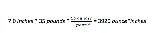
When designing a lift we need to determine the optimal gear ratio to allow our lift system to lift the robot but still do it relatively fast. Realistically looking at the aluminum parts we are using we plan for the robot to be around 35 lbs. We also know that the lander is 22 inches above the ground and we plan for the linear slide to extend to 14 inches off the ground This would mean that the point of rotation for our hook mechanism would be 22 inches - 14 inches = 7 inches below the latch on the lander.
We plan to use REV 40:1 motors that have 594.7 oz*in. Now using these calculations we can determine our needed gear ratio.
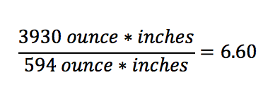
This gear ratio of 6.6 means that for our robot we need a motor to gear ratio that needs around seven rotations of the motor to provide one rotation of the hook.
We knew the max weight of the robot would be around 20 pounds since the total weight of all the parts in the kit is less than 20 pounds. The point of rotation for the hook would be around 5.5 inches below the lander latch. This is because the bottom of the hook is around 22 inches above the ground and the point of rotation will be around 16.5 inches off the ground so that we can account for space for a gear while staying within the 18 inch box. Below is the torque calculation.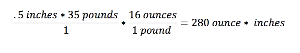
Next Steps