
Superman Calculations
Tags: think and designPersonhours: 3
Task: Calculate torque and other values of the Superman arm on our robot
We want to have our robot completely replicable through the journal. So, we found it necessary to include the power calculations of various subsystems on our robot.
Superman Arm
The Superman arm uses two REV Core Hex motors to lift the robot upward, outputting a base 125 RPM and 6.4 Newton-meters of torque. Then, we have 15-tooth gears attached to the motors, which in turn connect to 125-tooth gears for a gear ratio of 10.4:1. Using the torque calculation WheelT=MotorT*(output/input), we find that the total torque exerted downward by the arm is 66.6 N*m.
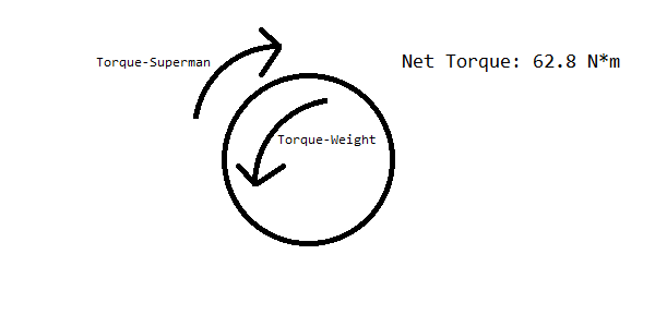
Then, given that the arm is .304 meters long, the upwards force produced by the Superman arm is 20.29968 Newtons. The robot itself weighs about 20 pounds, or 89 Newtons. But, since the robot is moving around its center axis, we can neglect the lower half of the robot that touches the ground with the wheels, reducing our load to 44.5 Newtons. Then, taking the integral of force with respect to the radius measured from the Superman arm, we integrate the equation force=(force at top/radius to top)*radius=292.763r. Using the limits defined by the distance to the edge of the robot (0 to .152 meters), the downward torque created by gravity is 3.38 N*m. Modeling the robot as a single point, we get this diagram.
But, the robot doesn't always operate at optimal load. For example, when the robot is at maximum extension, there are about 60N of load above the center arm and the center arm itself is extended 18 inches, or .4572 meters. Performing the same integral as before with the new limits (0, .4572+.152=.6092), we find that the maximum possible downward torque exerted on the arm is 54.33 N*m, resulting in a net torque of 12.7 N*m upward. Superman can still raise the robot upward, but much slower and with a much greater probability of gear slippage. At these torque levels, the plastic teeth of the gears slip if they're not perfectly aligned.
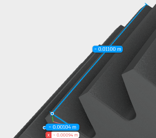
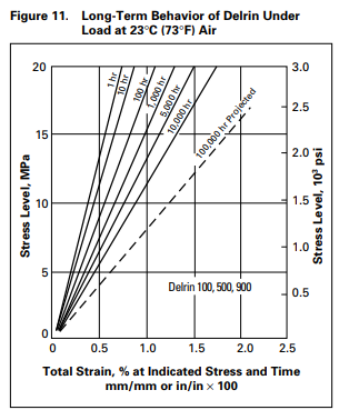
Given that the gears are composed of Acetal (Delrin/POM), that the area of one tooth is (.00104 meters * .011 meters = 0.00001144 m^2), that the arm produces 66.6 N*m * .152 m = 10.12 Newtons of force, and the Delrin/POM deformation chart, we can find that the pressure on *one* tooth of the gear is P=F/A=10.12/.00001144=884615.38 Pascals or .88461538 MPa. And, consulting the Delrin/POM deformation chart below, using the long-term line for an hour of use, we retrieve a stress of ~.5%, meaning that the teeth of the gears deform by .5% per hour of use. This alone explains our gear slippage under high loads; as the pressure on a tooth increases, they cause more deformation, which in turn results less area contact between the teeth of the gears, which results in more stress, causing a negative feedback loop.
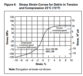
However, this alone doesn't explain the stripping of the gears - the gears would only deform by .0572 uM; more analysis is required. When we inspected the superman gears more closely, we found that the gears barely interlocked - maybe 1% of the gears were touching. When we go back to the pressure equation, we find that this increases the pressure on each tooth to 88 MPa. Under the short-term compression curve below, we find the strain is about 5%, or 10x the strain. This results in a deformation of about 5uM, but the contact area itself is only 104 uM, so under these loads it causes an appreciable effect.
This leads us to the natural conclusion to solve this issue - the gears must be held tighter to increase the contact area and decrease stripping. To do this, we're starting to design a gear holder, which will be detailed soon.