
Finishing Icarus' Base
Tags: think, design, and innovatePersonhours: 16
Task: Perform the final steps to complete Icarus' base
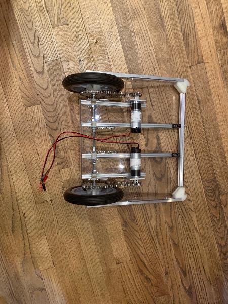
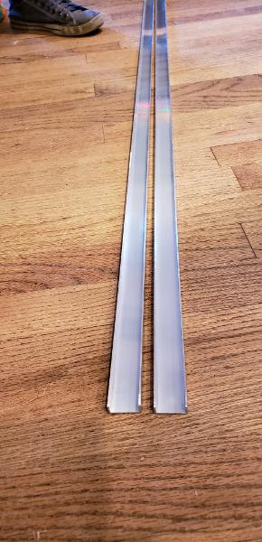
Since we finished the polycarb base, our robot went through some major changes. We last left our robot in the post-bend stage, just a piece of polycarbonate. The first thing we did was to square the whole robot with side brackets. These cleanly ripped aluminum C channel side brackets now serve as the highly accurate frame of our robot, which has been measured down the millimeter for the highest level of precision yet.
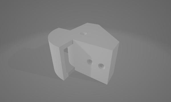
After creating the side brackets, it was time to give them the right holes in all the right places. The holes for the rod we use as our drive shaft were drilled in the side brackets, exactly the same on either side, as were the holes for the points of attachment on either side of the robot, connecting the base to the brackets. The front bracket was cut to size and placed on the robot after the REV rail we use as an attachment point for the elbow joint was placed. Then we put the 3D printed brackets onto the REV rails that make up the back end of the frame of the robot, running the bar that became the axle for the wheels. If you want to see just how far we’ve come, you can look back at the article that Arjun and Karina wrote about building the first version of the robot over the summer. The amount of improvement is large and part of the journey. Everything on the robot is done for a reason, be it stability, weight, or efficiency. This time around we’ve significantly reduced the number of extra things on the robot, and simplified it as much as we possibly can.
Next Steps
The next step is going to be told in an upcoming article that will describe the process of building the arm mount. If this robot is going to be on the field and compete, it needs the elbow joint to be constructed, so that’s next on the evolution of the new robot.