
Icarus' Superman Arm
Tags: think, design, and innovatePersonhours: 8
Task: Design and install a lifting arm for Icarus
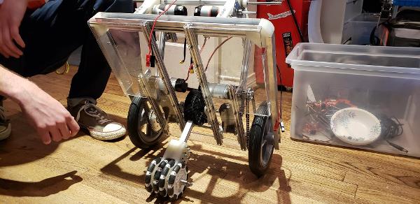
At the same time as the elbow joint was being done (which can be found in the article "Constructing Icarus' Elbow”) the Superman lift was being installed in the back half of the robot. The old superman system was difficult to install, but we designed it to be slightly easier. Mounting brackets were already pre-set in the robot so we didn’t have to disassemble half of the robot to be able to set screws into the extrusion rail. Bearings were inserted into the brackets, and the process of sliding all of the needed parts onto the rails began. First was the outside shaft collar, which holds the 6mm hex shafts in place. Then was the first interior shaft collar, which kept the internals in place. Then the first of the gearkeepers was put on, followed by a spacer meant to separate the gearkeeper’s bearing from being popped out by the gears on the Superman arm. Then came the actual Superman arm, which is one centimeter longer than our original arm, hopefully allowing more lift.
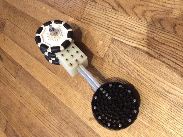
It’s made of three 125 toothed gears from REV, with the center one’s ridges drilled out, a REV rail sized chunk sawed to insert our actual lever bar, and 3D printed spacers separating each of the gears around the outside which have all been bolted together. On the end of the bar is a 3D printed holder for the four omni-wheels we’ve positioned there, which are all set with bearings for smooth motion. Once this was slotted onto the 6mm hex rail we added one more spacer, the other gearkeeper, then the final interior shaft collar. It was put through the other bearing and bracket on the other side and finally closed off with a lost final shaft collar on the outside.
After we got the arm in, we moved on to the driving 6mm hex shaft. Since this one was a lot longer and was hard to fit into the space provided, it was aligned in a way that it could slip through the slots of the wheels as we pushed it into place. We first put a REV core hex motor and a shaft collar that would work as the outside clamp. Then we put it into the bearing on the bracket and pushed it through. A shaft collar was placed, and then we attached the other end of the gearkeepers on. It was tight like we wanted it to be, but it didn’t make our builder lives easy. We put on a spacer to keep it in line with the Superman arm and then we put on the drive gears, three 15 tooth gears with the center one's sides cut off to mimic the Superman gears on the other side. After we put that in, we put another spacer and then the other side’s gearkeeper. This is where the struggle came. Since the gearkeepers keep the gears together exactly the distance from the center of the radius of the 15 toothed gear to the center of the 125 toothed gear, it was a very tricky squeeze to get it attached. After we managed to get it one, we put another shaft collar on and put it through the bearing on the other side. We slid on one last shaft collar on the outside, and ended the shaft with another REV core hex motor. That capped the entire subsystem off, and all that’s left is it to be wired.
This system differentiates us from other teams - our robot is able to deposit through a lever arm that rotates the robot itself, adding an additional degree of sophistication and mobility to the robot.
Next Steps
The subsystem needs to be completely wired and tested before it's approved for the final robot.