
Ring Launcher CAD Meets 1+2
Tags: designPersonhours: 8
Task: Begin designing a ring launcher
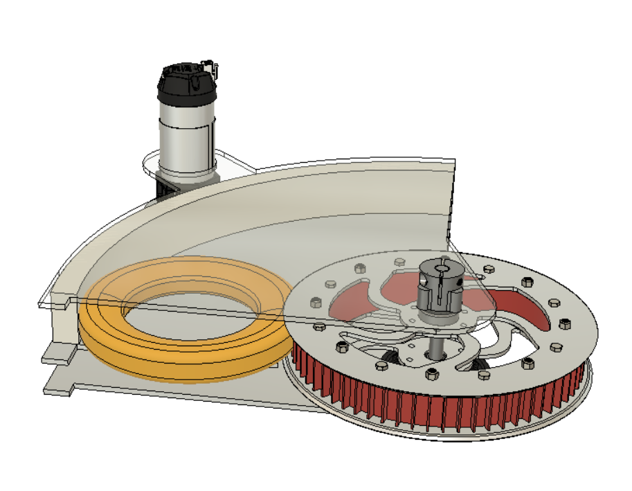
The initial vision for the ring laucher was to be a semi-circle in order to give the ring as much acceleration as possible. In this meeting, it was decided that instead it would be a quarter-circle for the following reasons: to save on space, since there will eventually also be an intake on the robot and a quarter-circle has been proven to give the ring enough acceleration, even if a faster motor is necessary.
With that decision made, the flywheel was placed in the CAD and the quarter-circle was brought into existance. There is a circular shaft in the center that will hold everything together, but the plate that the ring will rest on cannot be jointed to this shaft. This is because it has to clear the flywheel, so instead another aluminum plate will be placed below it to act as support. From there, walls were added to keep the ring within contact of the flywheel. These walls where also extended a bit beyond the quarter-circle, this is to prevent any variabilty in the lauching of the ring. Finally, a motor mount was extended out of the center aluminum plate to drive the flywheel with the use of a pulley and belt.
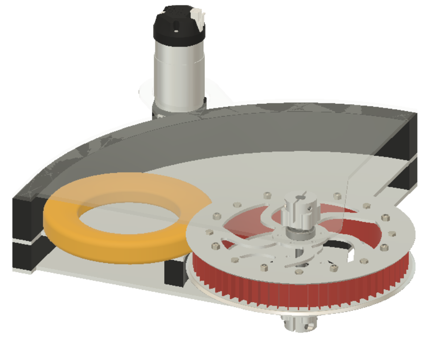
In the second meeting, some final design additions where made, namely screw holes were added(or removed, technically) from the plates and walls in preparation for 3-D prining and CNC milling. Additionally, any walls that were in the way of the belt driving the flywheel were split to make way for it.
Next Steps:
There are still many features to be added, such as a way to transfer rings from an intake to the launcher.