
Ringslinger 9000 Step-by-Step Guide
Tags: innovate and designPersonhours: 24
Task: assemble different intake prototypes
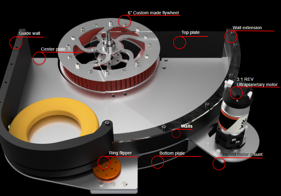
The Ringslinger 9000 is a crucial part of the robot and requires careful planning to build. Although we have a relatively simple intake and launching mechanism, their components are a bit more complicated. After getting the individual pieces of our launcher system ready, we were able to start putting them together to form the system. This post will serve as a step-by-step guide on how the entire launching system was assembled.
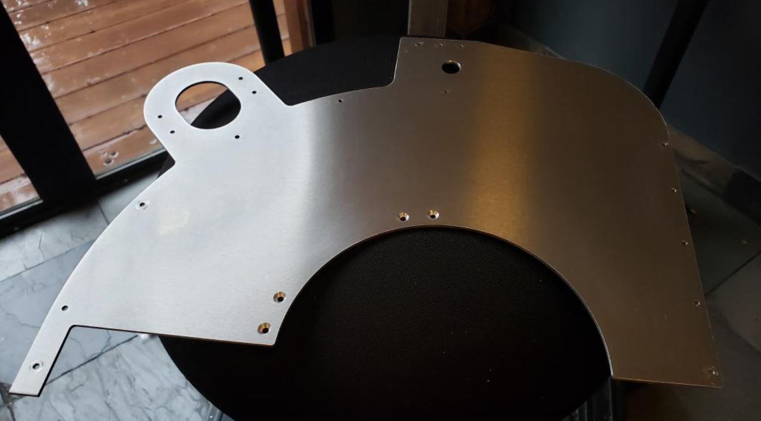
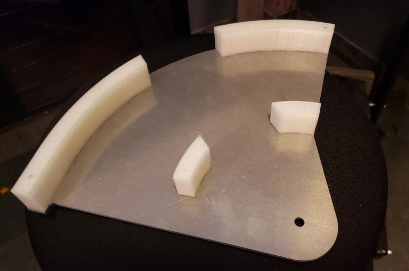
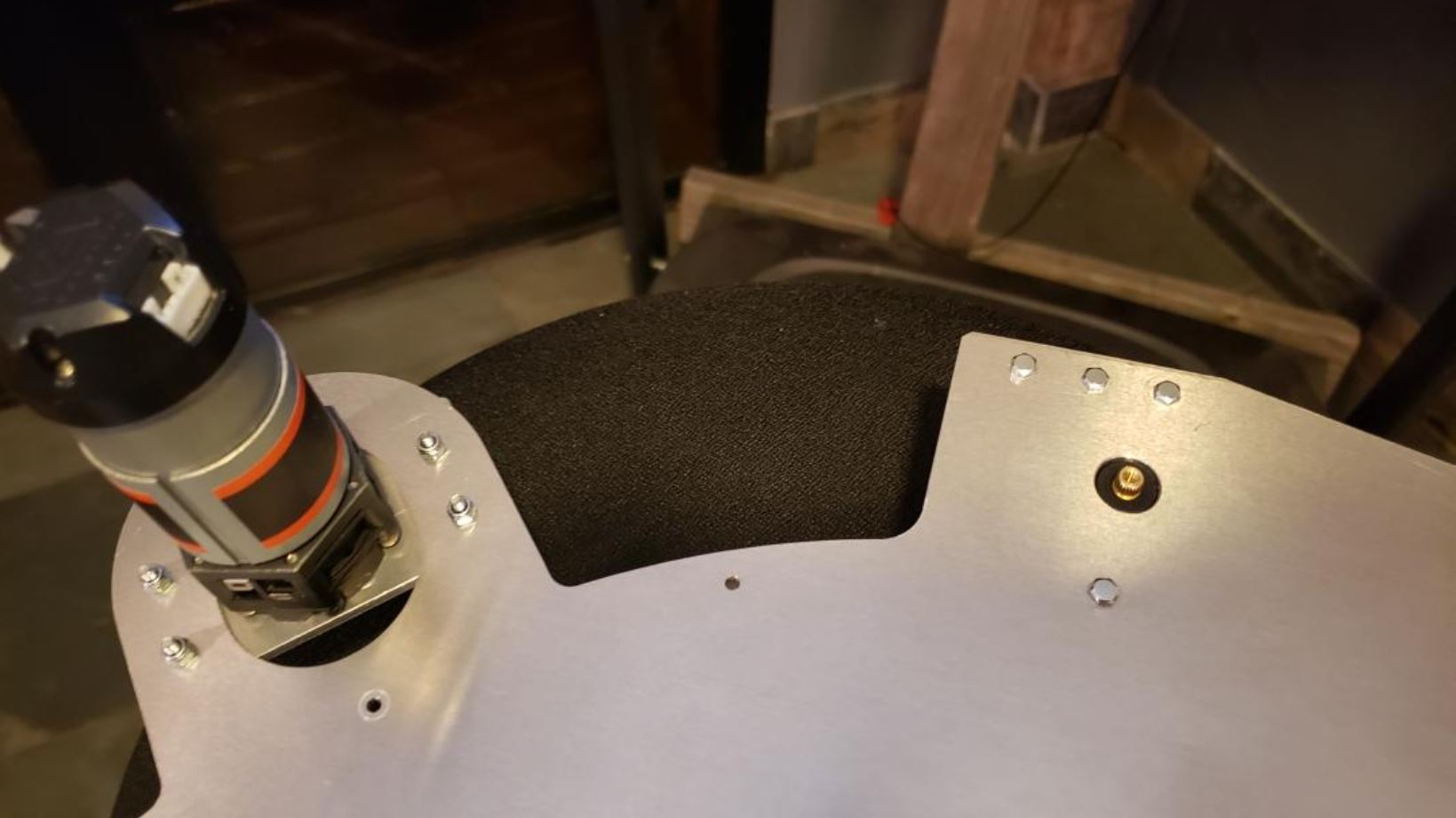
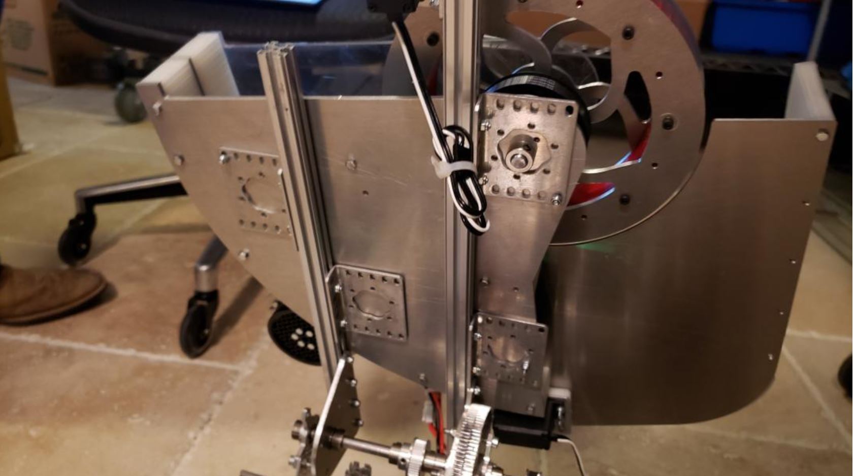
The process starts with the launcher baseplate which was constructed using aluminum and was cut on the CNC mill. As shown in the picture above, several holes were strategically placed in various areas on the periphery of the plate for screws to go to hold the other elements such as the Ultraplanetary REV motor that powers the flywheel and the nylon guide wall which guides the rings as they move through the system. The plate itself is mounted onto 2 REV extrusion bars using several metal brackets as shown below.
The bars are mounted onto a hinge which carries the entire system and rotates as needed during the game.
Launcher Guidewall/extension
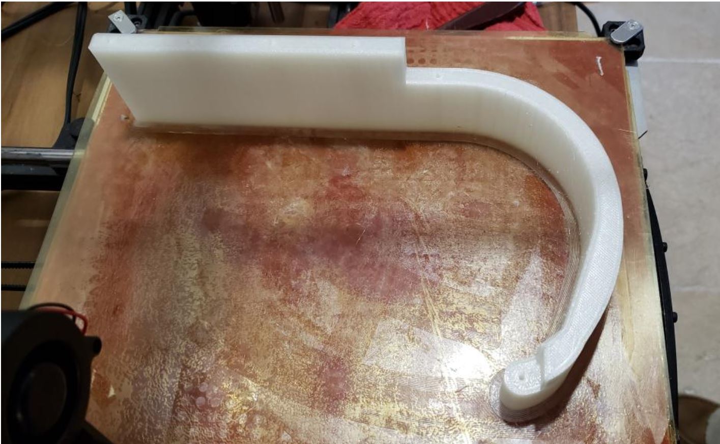
The custom-printed guidewalls are attached to the plates using retaining screws, and function to guide the rings to the flipper to be prepared for launching.
Motor Mechanism
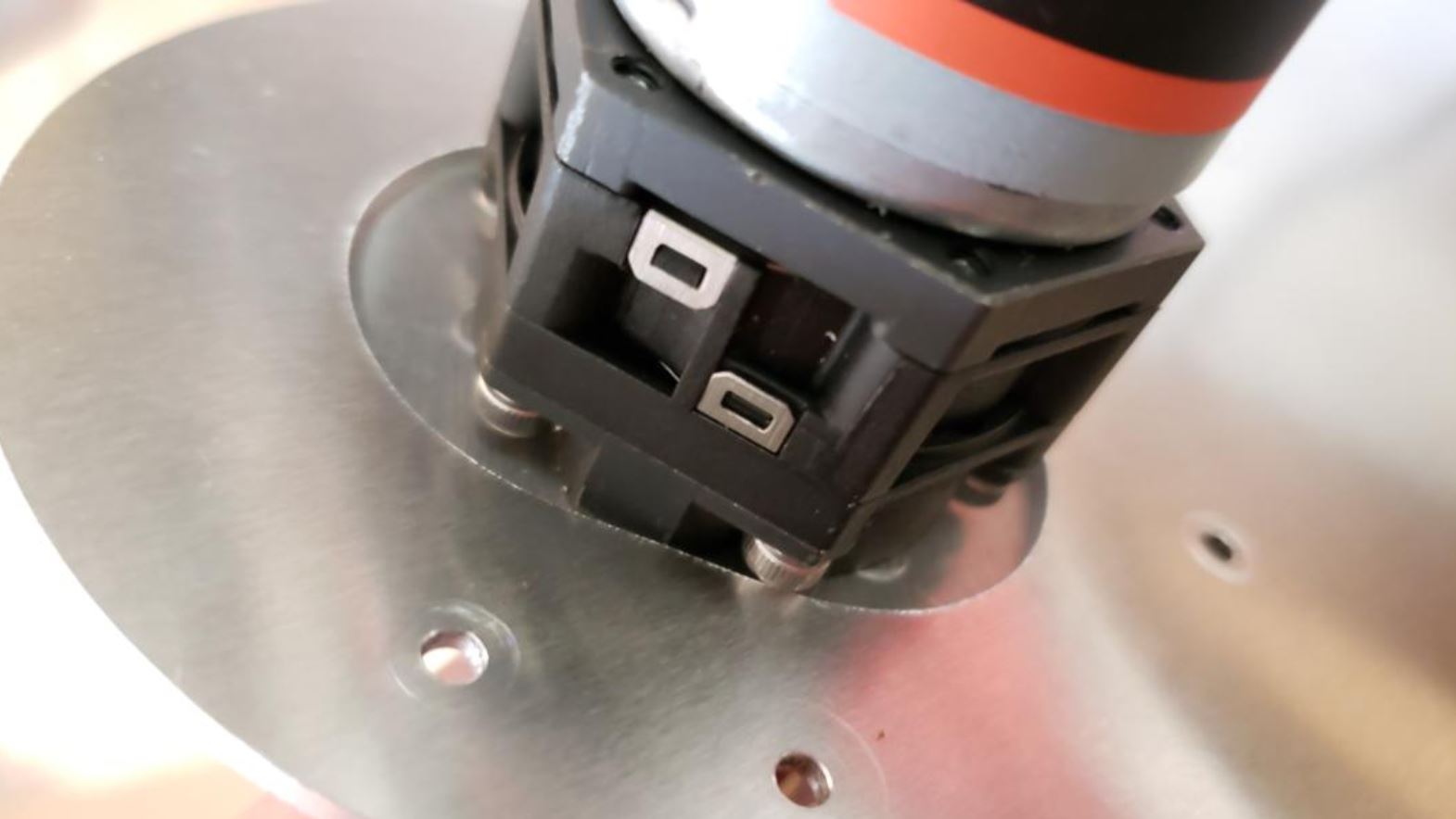
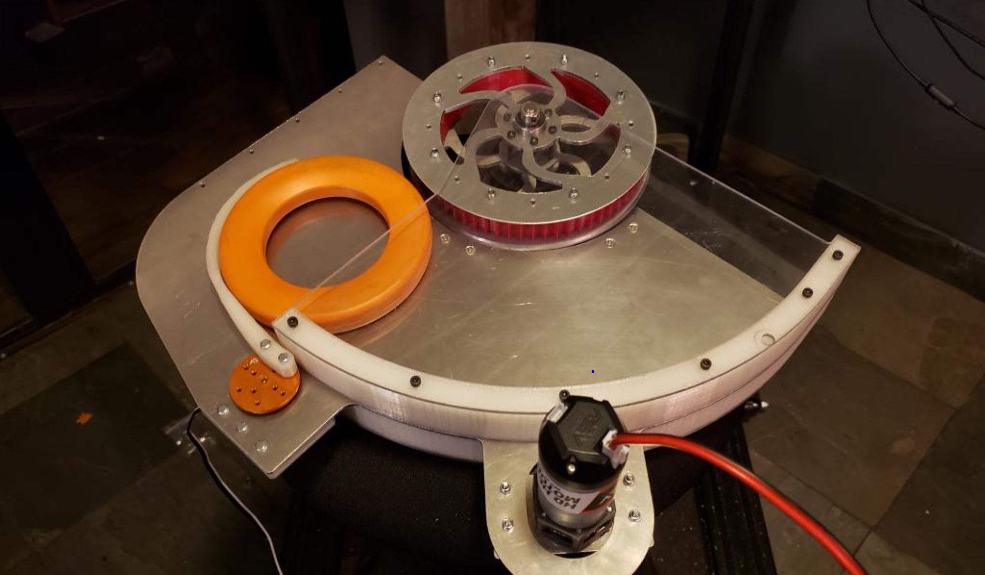
The REV 3:1 Ultraplanetery motor which drives the flywheel is attached via a slotted motor mount as shown below. It is then placed on an extension of the launcher baseplate using 6 screws. The motor can spin its sprocket at 1,727 RPM and drives the wheel by a belt between the two sprockets.
As mentioned in the Ring Launcher Summary, our launching system essentially is made out of 3 levels: the mounting, driving, and ring levels. The pictures below show the driving level's center plate with 3D printed nylon spacers mounted to separate it from the ring level. The spacers closest to where the flywheel will be attached each contain 2 holes and are attached by screws. The larger spacers also contain 2 holes where screws are attached to mount the driving and ring levels together. After getting the two individual levels ready, they are put together using screws, as shown below.

Shown below is the custom-made servo spacer. The servo is mounted next to the opening that is next to where the motor is mounted. It is fixed into place using screws.
Pictured below is a bird's eye view of the center plate. The servo located on the back of the ring slinger essentially spins the ring flipper to exert motion onto the rings to prepare them for launching by pushing them into contact with the flywheel. The REV Ultraplanetery motor is mounted onto the platform using 4 screws and nuts and the servo is mounted also using 4.
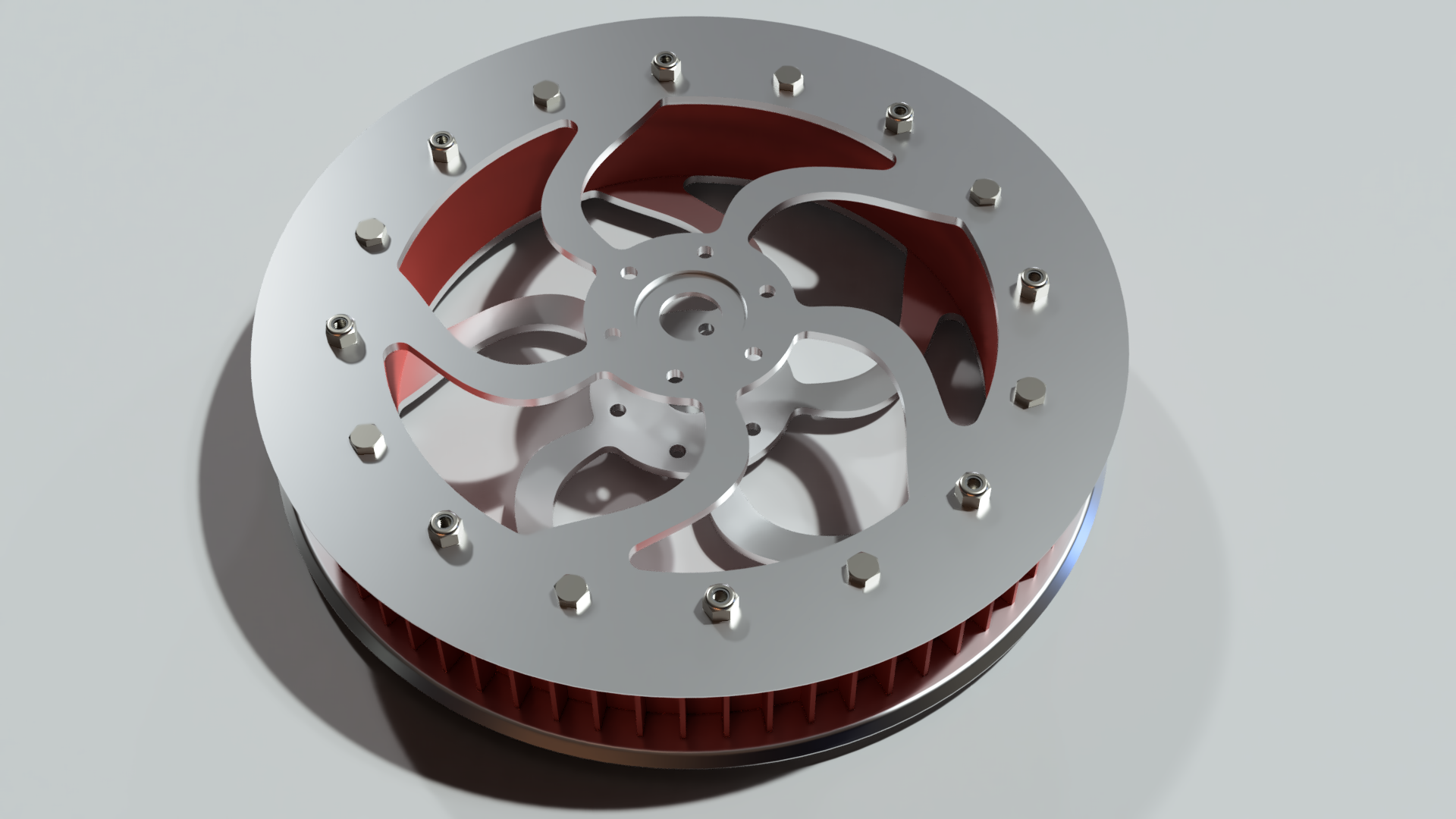
The flywheel is composed of a NinjaFlex center wheel which is sandwiched between 2 custom aluminum plates.
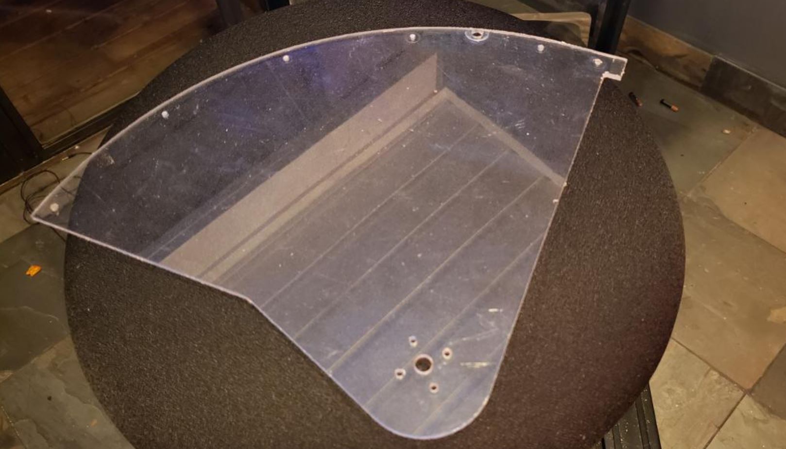
The flywheel's upper aluminum plate works to keep the wheel from flying upward. A polycarbonate sheet works with its lower aluminum plate to fix the axle in place. The polycarbonate sheet is shown below. It also plays a role in keeping parts in place.
The Flywheel is attached to a pulley which drives it using the belt that runs from the wheel pulley to the REV motor. As seen in the CAD model above and the picture below, the wheel was assembled by connecting the 2 aluminum plates to the NinjaFlex wheel in the center using screws. The flywheel spins on the shaft that is locked into place with the shaft collar on each end.
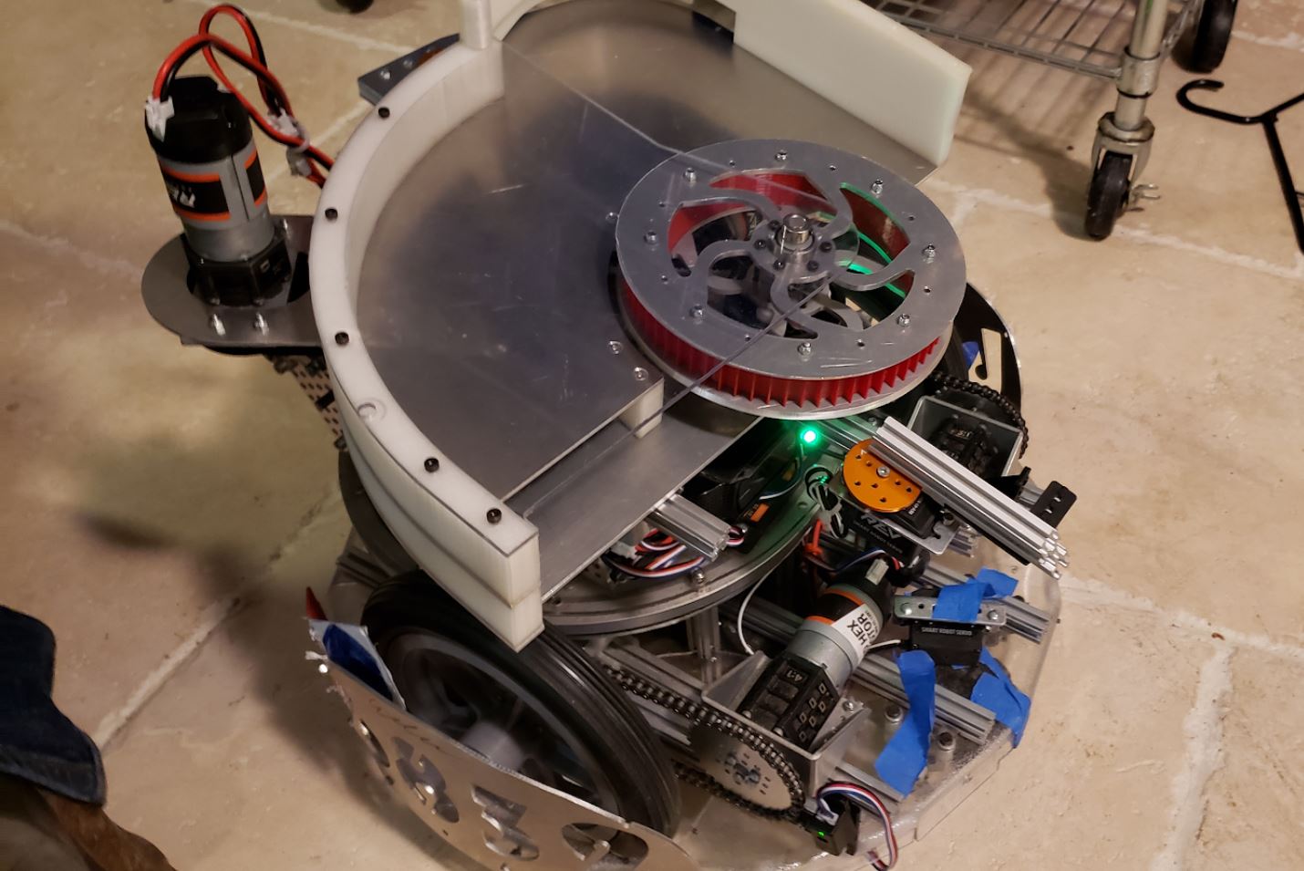
As shown above, the whole launching system to the arm that sits on a pivot in the back of the robot which adjusts itself by rotating to the angle that is ideal for where a ring needs to be launched to.
Finally, a look at the robot after all the individual parts were assembled is pictured below.
Next Steps:
One of the highlights of this system is that it is completely custom-designed and built . All our parts were either 3D-printed or custom-machined on our CNC. Documenting its assembly allows us to keep track of all of the parts involved in its print. Being able to showcase the build stages of the Ringslinger 9000 is also incredibly useful for two more reasons. First, if we ever intend to build a second one, we have the progress of the first one fully documented for inspiration and/or to isolate potential causes of structural error. Second, if any teams who follow our blog want to create a similar model, they have ours for a source to help. As the launcher continues to undergo changes, it is likely we will create another such assembly post - likely after our first qualifier in 3 weeks.