
Achieving Continuous Targeting and Launching
Tags: controlPersonhours: 15
Task: Achieve Continuous Targeting and Automatic Launching
With the goal of having the turret continuously aim towards the goal, the elbow tilt to the correct angle at will and the flywheel to ramp to the correct velocity at will, we began by verifying our odometry calculations using FTC dashboard. Our odometry calculations would be the cornerstone of our entire automatic launching system, since the distance between the robot and the goal as well as the bearing to the goal from the robot would both be determined using the robot's x and y position as given through odometry. Using FTC dashboard's field overlay, we were able to draw our robot as a circle onto the given canvas like so:
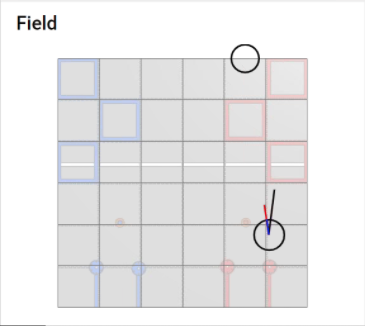
In the above image, the bottom circle represents the robot, with the top circle representing the goal. The longest black vector represents the heading of the drivetrain or base of the robot. The second to longest red vector represents the heading of the turret of the robot. The shortest blue vector, which is the same size as the circle robot itself, represents the bearing from the robot to the goal.
The blue and red vectors (bearing to goal and heading of turret) are equal in direction because of the PID loop running to continuously target the goal. We are able to accomplish this by setting the target heading of our turret PID controller to the bearing between the robot and the goal, which can be calculated with: \[\theta = tan^{-1}\left(\frac{y_{goal} - y_{robot}}{x_{goal} - x_{robot}}\right)\] The PID controller compares this target angle with the IMU angle of the turret and corrects for them to be equal.
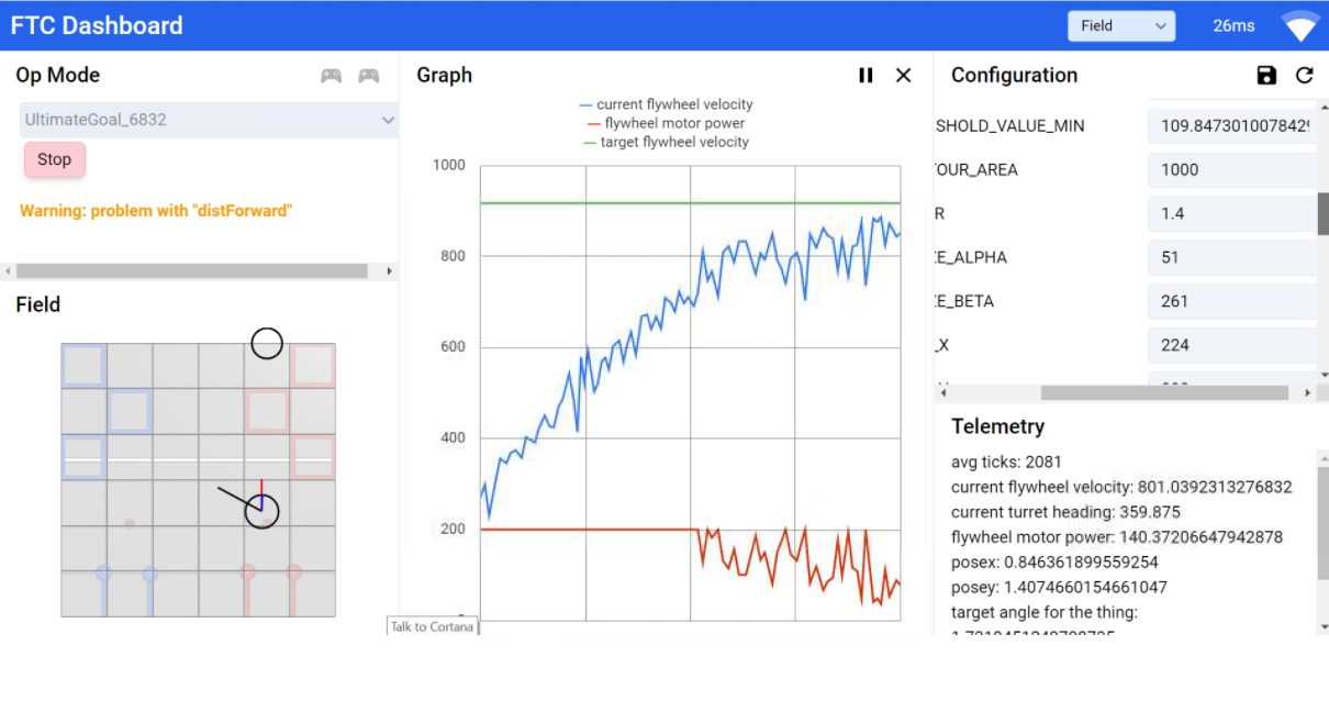
As for the other part, automatic launching, we were able to achieve this using our previously made trajectory calculator. The input to our trajectory calculator, the distance between the robot and the goal, was calculated using: \[distance = \sqrt{(y_{robot} - y_{goal})^2 + (x_{robot} - x_{goal})^2}\] The outputs of the trajectory calculator, the angle of elevation of the elbow and angular velocity of the flywheel, were then set to the targets of the elbow PID and flywheel PID controllers, in order to consistently hold the desired articulation. When the flywheel ramped up to a velocity in a 5% error threshold of the target velocity, we toggled the trigger servo and launched the disk, with the ramping of the flywheel seen below through FTC dashboard:
Next Steps:
By testing our continuous target and automatic shooting system, we quickly realized our calculations were slightly off. The next obvious step is to diagnose any sources of error in our calculations and account for them appropriately. The main one being how the angle of the launcher affects the vertical distance travelled by the disk (initial height of launch), and vice versa. This can be done using the convergent, iterative process described in a previous post. Other sources of error could include the turret being offset to the right of the center of the robot, and a later discovered glitchy flywheel power cable. We can now advance from simply implementing our theoretical calculations to diagnosing issues with them and addressing errors in our robot.