
Accounting For Offsets And Launching In Motion
Tags: controlPersonhours: 4
Task: Build A Forward Kinematic Model Of The Robot To Account For Turret And Muzzle Offsets, And Counter-Lead The Target To Allow For Launching In Motion
After building the base of a trajectory calculator to allow for continuous targeting and launching, the next step was to address the discrepancies between our robot in code and the real robot, a major one being the offset between the muzzle compared to the center of the robot. Thus far, we had been treating the muzzle exit point as the center of the robot, which in reality isn't the case. The center of the turret is positioned behind the center of the robot to be flush with the back edge, and muzzle is positioned in front of and to the right of the center of the turret. In order to account for these offsets in code, we would have to build, in technical terms, a forward kinematic model of the robot to figure out the final (x, y) position of the muzzle, or the point at which the disk leaves the robot.
To account for the turret's offset we calculated the center of the turret to have the coordinates: \[\displaylines{x_t = x_r - dcos(\theta_r) \\ y_t = y_r - dsin(\theta_r)}\] where \(x_t\) and \(y_t\) represent the x and y coordinates of the turret respectively, \(x_r\) and \(y_r\) represent the x and y coordinates of the robot respectively, \(d\) represents the distance between the center of the robot and the center of the turret, and \(\theta_r\) represents the heading of the robot's base.
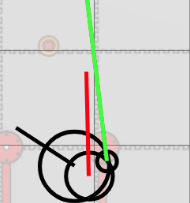
We then took \(x_t\) and \(y_t\) and used them to calculate the muzzle exit point using a polar approach: \[\displaylines{x_m = x_t + rcos(\theta_t + \theta_m) \\ y_m = y_t + rsin(\theta_t + \theta_m)}\] where \(x_m\) and \(y_m\) represent the x and y coordinates of the muzzle respectively, \(\theta_t\) represents the heading of the turret, and \(r\) represents the "radius" of the muzzle, and \(\theta_m\) represents the "angle" of the muzzle. In reality, the terms "radius" and "angle" of the muzzle don't make sense since the muzzle is positioned in front of and to the right of the turret, and using a cartesion approach we would have to make two separate adjustments for the x and y for the vertical and horizontal offsets, however converting these offsets into a polar form can help to simplify the process, and is where a "radius" and "angle" are derived from. If the horizontal distance between the muzzle and the turret center is \(o_x\) and the vertical distance between the muzzle and the turret center is \(o_y\) (when the robot is viewed from the top-down), then \(r\) and \(\theta_m\) can be derived like so: \[\displaylines{r = \sqrt{o_x^2 + o_y^2} \\ \theta_m=tan^{-1}\left(\frac{o_y}{o_x}\right)}\] \(r\) and \(\theta_m\) are used in the previous equations for \(y_m\) and \(x_m\) to derive the final position of the muzzle exit point, and completes the "forward kinematic model" of our robot for trajectory calculation purposes. \(x_m\) and \(y_m\) are then substituted for \(x_r\) and \(y_r\) in all trajectory calculations to account for all offsets from the center of the robot. In the first image on this post, the turret can be seen repositioned from the center of the robot with a heading labeled with a red vector, and the muzzle can be seen with a smaller circle containing a neon-green line to the currently selected target.
Our second task was to allow the robot to launch at its target while in motion. The first step of achieving this would be to address how the robot's velocity in the x direction would affect the trajectory of the disk. We would have to counter-lead the target in the x direction to account for side-to-side motion of the robot while launching. This is because when the robot is moving with a velocity \(v_x\) in the x direction while launching, the target will be offset by a factor of \(v_x \cdot t\), where \(t\) represents the time the disk spends in the air. To account for this we can simply subtract \(v_x \cdot t\) from the target's x position in order to counter-lead it.
To account for the robot's velocity in the y direction (\(v_y\)) we can subtract \(v_y\) from the disk's horizontal velocity calculation, which then becomes \(\frac{d}{t} - v_y\). This effectively adds the robot's y velocity onto the y velocity on the disk, which reduces the needed horizontal velocity of the disk, hence why \(v_y\) is subtracted.
With these two additions, we can now, at least theoretically, launch in motion. In practice, we saw that our underdamped PID controller could not keep up with the bearing to the counter-led target. In a perfect world, the turret's heading would equal the bearing the offset target, although due to poorly tuned PID coefficients, this was not the case. With some tuning we hope to correct this and get the turret to somewhat lock on to the offset target while the base is in motion.
Next Steps:
Our next steps would be to continue addressing small errors in between our robot in code and our robot in the real world, perfecting our trajectory calculator to maximize accuracy and precision. From a few tests we determined our successful shooting rate was around 75% from a fixed location, which can be used to conclude that there are mechanical faults at play as well, which could be a non-stationary elbow or unbalanced flywheel. These are all investigations to delve into later in order to perfect our automatic launching.