
Deriving Maximum Chassis Length On Turns
Tags: think and controlPersonhours: 40
Task: Derive The Maximum Chassis Length On Turns
Having a chassis able to elongate and contract during play poses its advantages and drawbacks. If properly used, the chassis can serve to strategically defend portions of the field. However, if not shortened during turns, the extended length of the robot can lead the swerve wheel to lose traction and start skidding on fast turns. Therefore, it is crucial to derive a model for the maximum chassis length achievable on a turn of angular velocity \(\omega\) before skidding starts to occur.
More concretely, the problem is the following: given an angular velocity \(\omega\) and other physical constants, what is the maximum distance \(s\) achievable between the front axle and swerve wheel before the centripetal force required to keep the robot in circular motion \(F_c\) exceeds the force of friction \(F_f\) between the wheels and the ground?
To start, we can define the force of friction \(F_f\):
\[\displaylines{F_f = \mu N = \mu mg}\]where \(\mu\) is the coefficient of friction betewen the wheels and the ground, \(m\) is the mass of the robot, and \(g\) is the acceleration due to gravity.
Then, we can define the centripetal force required \(F_c\):
\[\displaylines{F_c = ma_c = m\omega^2r_s}\]where \(a_c\) is the required centripetal acceleration, \(\omega\) is the angular velocity of the robot, and \(r_s\) is the distance from the swerve wheel to the center of rotation.
Setting these two equations equal to eachother and solving for \(r\) will yield the final equation:
\[\displaylines{F_f = F_c \\ \mu mg = m\omega^2r_s \\ \mu g = \omega^2r_s \\ r_s = \frac{\mu g}{\omega^2}}\]However, the \(s\) must be related to \(r_s\) to be used in the above equation. This can be done by substituting the expression \(\sqrt{r^2 + s^2}\) for \(r_s\), where \(r\) is the true turn radius, which will compute the distance from the swerve wheel to the instantaneous center of rotation. So,
\[\displaylines{r_s = \frac{\mu g}{\omega^2} \\ \sqrt{r^2 + s^2} = \frac{\mu g}{\omega^2} \\ r^2 + s^2 = \left(\frac{\mu g}{\omega^2}\right)^2 \\ s^2 = \left(\frac{\mu g}{\omega^2}\right)^2 - r^2 \\ s = \sqrt{\left(\frac{\mu g}{\omega^2}\right)^2 - r^2}}\]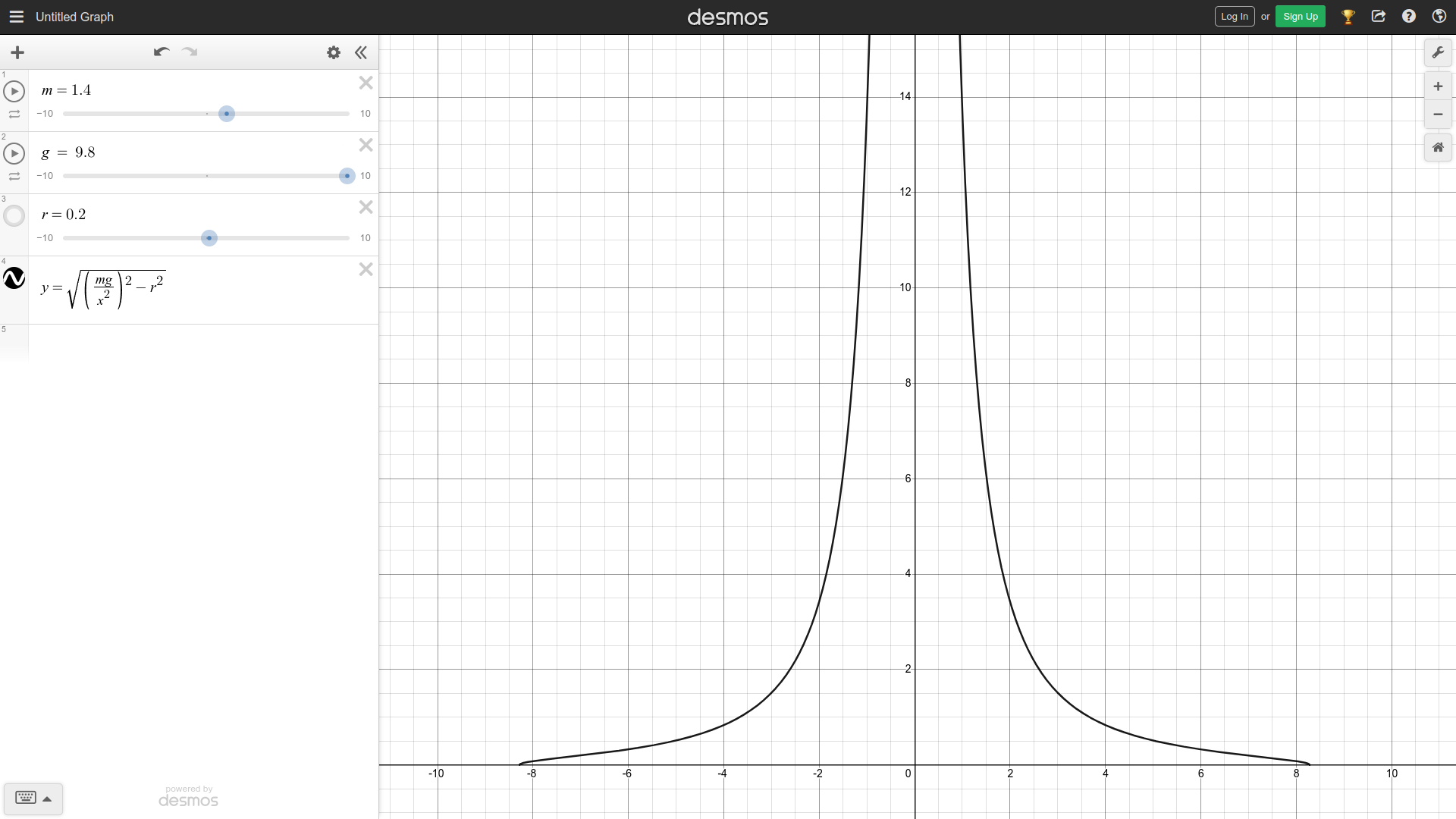
As seen in the above screenshot of the following desmos calculator, the slower the robot rotates, and the closer \(w\), or in this case \(x\), is to 0, the higher the maximum chassis length \(s\), or in this case \(y\), is. Intuitively, this checks out, since when at a standstill, the robot can be as long as possible with no side effects. When rotating slowly, the robot needs to be slightly shorter to maintain traction, and when rotating fast, the robot needs to be very short to maintain traction, as reflected in the downward slope of the graph.
Next Steps:
The next step is to use PID control with input as the measured chassis length as given by the distance sensor and target being the output of the derived equation for \(s\) to maintain the robot's length to keep traction. Additionally, the coefficient of friction \(\mu\) between the wheels and ground will need to be tuned to the drivers' liking.