
An Overview of the R2V2 Steering Wheel
Tags: journal, innovate, design, and thinkPersonhours: 36
Task: Design a subsystem to control the steering wheel of R2V2
One of the main components of our mission to make a remote-controlled RV was figuring out how to automate our steering wheel.
Step 1: Designing the plywood base for the steering wheel
Our first plan was to attach a sprocket and chain to the plywood base for the steering wheel. We knew we needed a plywood base because it would be both lightweight enough to easily be removable and attachable onto the steering wheel, and sturdy enough to handle a motor with high torque without splitting. While trying to screw in the sprocket to the base, we realized we didn’t have a convenient way to attach the motor assembly and the chain would most likely “lock up” if we tried to constantly move it forward and backwards.
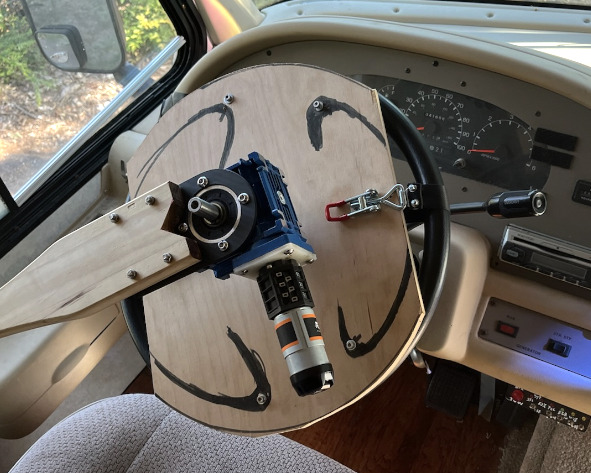
We settled on a design using a worm gearbox and the REV ultra planetary motors. We used a paddle to keep the worm gearbox and motor stationary so the steering wheel could move. The paddle was latched onto the window using REV bars and attached to a carbon fiber plate, which was then secured onto the worm gearbox. We used a second carbon fiber plate to attach the shaft collars on the axle of the worm gearbox to the plywood base, and made sure the shaft collars were tight enough to not spin on the axle when high amounts of torque were applied with the worm gearbox.
Step 2: Attaching the plywood base for the steering wheel
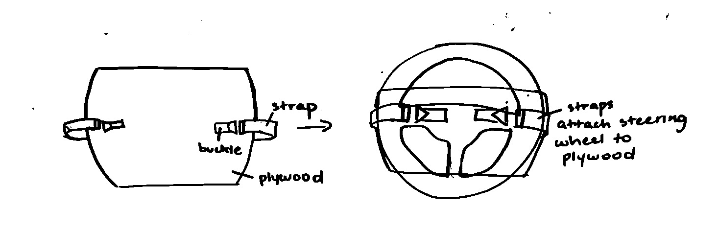
We didn’t want to make any permanent changes to the RV, so we devised a system to attach the plywood base to the steering wheel using straps and buckles. We attached the buckles to 2 sides on the top of the plywood, and attached one end of the straps onto the back of the plywood. To attach it, the straps go under the steering wheel and latch onto the buckles on the top of the steering wheel, securing the plywood to the steering wheel.
Step 3: Coding and calibration!
After we finished the design portion of the steering wheel we had to get it to actually move. We needed to not only map the left and right motion of the steering wheel to buttons on the logitech controller we are using for the R2V2 but also to know where the wheel is in relation to its maximum rotation to either side at all times.
In order to find the maximum rotation of the wheel we had to spin it all the way to one side. We need to find a way to know in the code that we reached the end of how far we could turn. For this we decided to test to see if the motors stalled because when the motor cannot move the wheel anymore in a direction its amperage spikes. This makes up our calibration mechanism. We spin the wheel all the way to the left and when it stalls we record the encoder position as the max left we can go. Then we spin the wheel all the way to the right and do the same thing but with the max right. We then find the distance between the max left and right and assume the middle of those numbers is center. To finish the calibration we run the wheel to center and then set that encoder position to 0 for easy readability for the driver. Left is negative and right is positive. Finally as a sanity check we make sure the encoders were recording values and if they were not we stop the robot as a safety precaution.
This procedure gets us the precise location of the wheel relative to where it is, and we can safely run the robot using the controller.
Next Steps
We are hoping to further test R2V2 and extend upon its capabilities and further share our progress through our blog, socials, and Youtube.