
Lessons We’ve Learned Switching from CAD to a Physical Model
Tags: journal, innovate, design, and thinkPersonhours: 48
Task: Overview the issues with PPE V3 and the changes that need to be made.
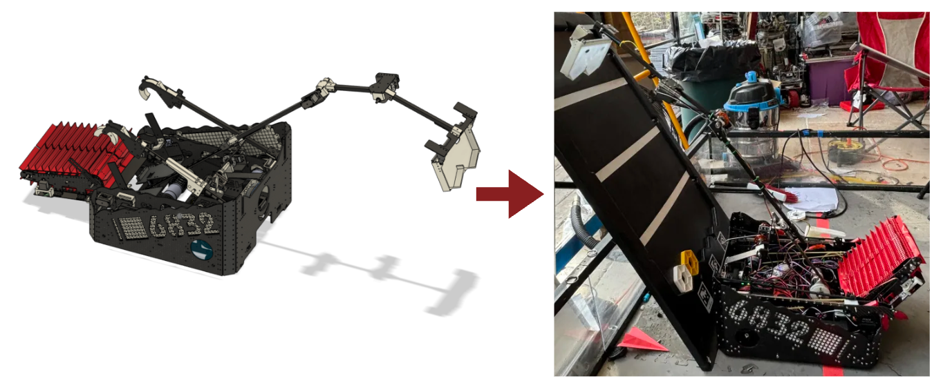
This past weekend, we had our regional competition! We were incredibly fortunate to have gotten Inspire 3 and were the 5th advancements to the FTC Texas State Championship in a couple weeks! However, we went into Regionals with a robot we had barely finished building due to an incredibly long design season, and we had barely any robot game, except for our Skyhooks. There were also a lot of challenges that came up as we built our robot from machined parts. Here are some of the problems we noticed and steps we are going to take to fix them.
Intake (Pixinerator):
- The new robot is way too wide, the two main causes are 1. Intake width and 2. Electronic plate wiring(where the control & expansion hub are mounted)
- Solutions:
- We can narrow the intake because the current size is completely random (<3 pixels, >4 pixels) and it probably won’t have the worst repercussions
- Drivers may decide that the width isn’t an issue because of the new corner deflectors and we can continue using this iteration of the chassis
- Pixinerator is intaking unevenly (thinner carbon fiber plate isn’t as rigid as the 2 mm aluminum plate we were using initially, the side without servo power isn’t being pushed into the mat with enough force)
- Routing cables also needs to be improved, not enough space for a second servo because of how things were routed
- Solution: Use two intake servos as opposed to one so both sides of the Pixinerator will receive servo power
Outtake (Ralph):
- Ralph is getting caught on the surgical tubing used to assist Pixinerator
- Solutions:
- Possibly move the surgical tubing to the inside of the nacelle (side wise) and attach to back plate
- Create new attachment point for longer bolts which attach further back on the Pixinerator side plates so it doesn’t interact with the inside of the nacelles
- Many issues occurred with Crook moving while we were trying to outtake pixels(electrical problem, bad connection between the Crook servo) → we generally have wiring problems/power injection problems, need to be sorted out
- Hinges and Clamps (Joints)
- The carbon fiber tube clamps allow sideways movement → too much wiggle (cf tubes are not held square towards robot)
- Pillow blocks and how they accepted bearings also had a lot of wiggle
- Solutions:
- Switch over to using bearing blocks as opposed to bearings
- Possibly moving the REV bearings to the inside of the pillow blocks to lock them in place
- Nothing is retaining the axle on far side of pillow blocks (axles twisted and slid)
- Solution: Switch to using locking hubs
Chassis:
- Support for cable management/cable runs was not properly considered by design team because of a time crunch
- Hand-held drilling may be our only option
- LEDs
- Back camera LEDs need a place to mount to as well as wiring and battery solutions
- Battery Compartment
- Current battery compartment “door” doesn’t open fully because the back plate doesn’t have enough clearance
- The hinge for the battery compartment is incorporated within a structural element which results in a very weak design
- Solution: Redesign battery compartment door so it can open fully and is stronger
Dock:
- Dock flaps were interacting with Pixinerator when it is completely vertical
- The forward boundary for Ralph wasn’t effective in real life even though it looked like it was in CAD. It also doesn’ seem necessary because Ralph can bottom out by itself
- Parallel alignment with Pixinerator can be done w just pins instead of forward wall
- Either it retains pixels or the pixels will slide out of robot by way of dock so we won’t get penalized
- Passive dock roof doesn’t seem feasible → just too many problems :(
- Solution: Possibly attach dock roof to inward facing inner nacelle walls, operated by micro/mini servos
- Test high speed intake to see what kind of hand-held roof placement prevents pixel ricochet
- Bridge needs to be 8-10 mm lower because Scoopagon doesn’t get low enough to intake from pixel stacks
- Solution: pacers can be printed which go between the L beams that connect the bridge and the inner nacelle walls
- Camera was too high: it could not see when scoopagon was up and could not interact when scoopagon came down
- Solution: We need to redesign a front camera mount and possibly illuminate it
Drone Launch:
- Drone clamp is too weak, doesn’t stop the drone from being knocked off the robot by rigging or interaction with anoth
- Solution: Drone clamp should cover at least half of the drone, or double as a hangar for the drone - cover it completely
- Physical prototype and test first
Skyhooks:
- Still having rubber band/tensioning issues but that’s more of a set-up thing, doesn’t necessarily need a design change
- Had to abandon the concept of the limit switches to detect when they're fully up due to having to manually drill holes to increase clearance of Skyhooks with Pixinerator side plates
- Mount the IMU
Date | February 27, 2024