
Arm Mount Iterations - V1 through V3
Tags: journalPersonhours: 16
Task: Improve our Arm Mount
When we decided to switch to a worm gear as our shoulder as opposed to a coaxial shoulder or a bridge mechanism as our earlier robot had, we had to consider how we were going to attach the linear slide arms to the worm gear axle.
V1:
Because the worm gear axle has a key to help a shaft collar or a mount adhere, we designed our first model of the arm mount with a slot to slip onto the key, and holes which were the appropriate size to attach to our custom nylon spacers.
Additionally, because we were trying to repurpose our last year’s chassis for this year's game, we had to make the arm mount L-shaped so it could clear the top of the back plate.
We quickly came upon a problem: because of the high amount of torque required to rotate the full (heavy) arm assemblies, the 3D printed spacers were deforming and were no longer reliable. The same issue would occur every time we printed another set of 3D printed spacers so it was like putting a bandaid on a bullet hole; we needed to find a new solution.
V2:
We switched to a 14 mm metal keyed flange as opposed to the 3D printed parts so we had to repurpose our arm mount. In addition, we used to put the arm mount on the inside of the assembly so it would be flush against the wide side of the 3D printed spacers, but for additional strength, we wanted to make a wider center hole so we could put the mount against the flanged edge. This meant we lost one set of holes we were using to attach the mount to the spacers, but it was no longer necessary.
At this point, we were still using last year’s chassis so we retained the odd L-shape of the mount.
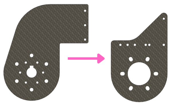
V3:
Ideating for our new chassis had started so we had to switch over to a more efficient arm mount. One of our goals was getting the linear slides in an intaking position when they were fully parallel to the ground so we had to get them closer to the chassis base plate. Because our new chassis is designed for this game, we could mount the shoulder lower to the ground and we no longer had to clear a back plate, making our new arm mount design simpler.
We also switched to cheaper metal keyed flanges which didn’t have the most precise hole locations, so we added slots to the holes which connect the mount and the keyed flange. While the earlier mount designs were designed with a 12 mm hole distance on the linear slides in mind, we swapped to a hole pattern which can accommodate both a 12H slide and a 9H slide so anyone on the team can reuse this design in the future. We retained the wider center hole which we had in the last mount.
We have an additional carbon fiber plate on the linear slides to help attach a pulley for our belted system, which we incorporated into this plate so we can push the linear slide mount further back.