
Launcher in 2 Days
Tags: outreach and motivatePersonhours: 80
Our “Launcher in 2 Days” (Li2D) experiment kicked off immediately after the game reveal as part of Iron Reign’s tradition of rapid prototyping to better understand each season’s challenges. While we explored multiple launcher concepts during Li2D, our flywheel design showed the most promises and became the foundation for future iterations.
The core idea was straightforward: a single rotating flywheel that would sweep up artifacts and launch them at a 45 degree angle. To guide the artifact's trajectory. We designed curved rails that would direct the artifacts as it left the flywheel. We used MDF prototyping sheets to create a circular board that allowed us to quickly test and adjust the launcher geometry, cutting it so the ball would exit at approximately 45 degrees.
For our initial flywheel, we utilized a foam-filled tire with aggressive tread. This off-the-shelf component provided excellent grip on the artifacts, which was crucial for imparting enough energy to achieve the distance and height we needed. The existing tire system, however, did have its challenges because getting it to spin at the right speed proved to be more difficult than we anticipated. Our first attempt used a preexisting 12:1 gear ratio, but initial testing revealed this was far too high because the wheel was not moving fast enough. We reduced it to 5:1, expecting better results, but discovered the sprocket system had its own built-in gear ratio that was still limiting the RPM. We ultimately went to a 1:1 ratio, which gave us significantly better rotational speed. However, it became clear that while foam tires provided good traction, we would need to build our own custom flywheel to achieve our target performance.
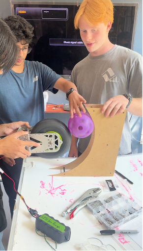
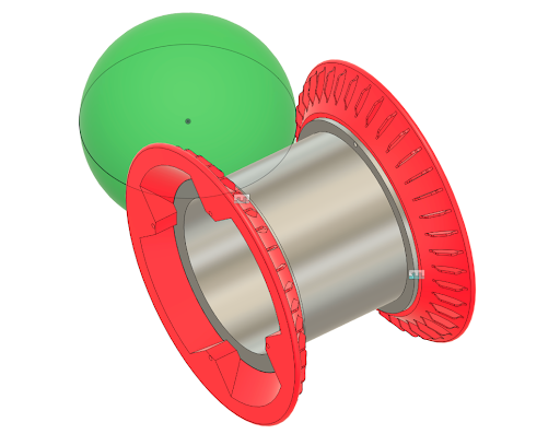
Consistency became our next major hurdle. Some shots would veer off to the side or fail to achieve proper height. Slow-motion footage of the flywheel in action revealed a part of the culprit. The surgical tubing was expanding as the flywheel spun, creating gaps during contact with the artifact. The flexibility that gave us a good grip was also introducing unpredictability. The tubing would deform differently depending on the ball's orientation and the exact contact point, leading to inconsistent energy transfer. It became clear that our next iteration would need a more rigid structure and much tighter control over the initial contact point with the ball.
The Li2D flywheel successfully validated the core concept of our flywheel design. We identified the critical challenges we would need to solve with our future iterations, and the lessons learned here will directly inform our v1 of the flywheel. Check out the video form of Li2D that covers even more insights!