
Flywheel V2
Tags: journal and thinkPersonhours: 2
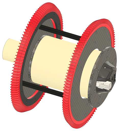
Since designing, building, and testing the first iteration of our flywheel, we’ve made some minor but important changes to the design. These changes resulted in the flywheel being capable of launching with enough power. While the results are satisfactory, we will continue to improve and experiment on this design as well as possibly test different flywheel concepts entirely.
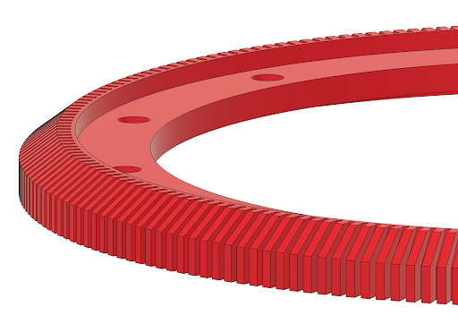
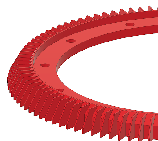
The major difference between v1 and v2 are the flaps that cover the outermost face of the T-tires. During testing of v1, we noticed that there wasn't enough traction between the Artifacts and the flywheel. For this reason we’ve redesigned the flaps to be 5mm long, 0.4mm thick (which is as thin as we could print them), and reduced the overall number of them. This resulted in the flaps actually being flexible instead of being stiff, similar to how they were on the original T-tires. On the top image is the T-tire design used in v1 of the Flywheel and on the bottom is the design used for this version of the Flywheel.
In addition to the new flap design, we also replaced the 3D-printed nylon standoffs that connected the two sides of the flywheel with COTS aluminum hex standoffs. We made this change to increase rigidity and reduce unwanted wobble, which was a recurring issue we encountered while testing v1. Similarly, we swapped the nylon ring that sandwiches the T-tire for one printed in PA-CF. The original nylon ring deformed when the bolts were tightened, while the PA-CF version provided noticeably greater rigidity and structural stability. However, even the PA-CF ring remains somewhat weak under high stress. In future iterations, we plan to either machine the rings out of metal (potentially copper, brass, or steel) to both strengthen the assembly and add weight for increased rotational momentum, or redesign the part to accommodate thicker sandwiching rings.
Despite these improvements, v2 still doesn’t produce enough power to be fully reliable when used on our first iteration of a stand-alone launcher. To help combat this issue, our next focus area will be increasing the friction within the system. Potential solutions include enlarging the T-tires (specifically by extending and heightening the flaps) or adding strips of TPU with flaps along the launcher’s back rails to enhance artifact contact. Additionally, we’ve observed the motors heating up quickly due to the enclosed design of the shell, so ventilation holes will be added in future versions to improve airflow. Finally, while rigidity has improved, there is still some unwanted wobble, which we suspect is due to the standoff-based structure. Our next design will likely move away from this approach entirely, and we instead would use a secondary shell to connect both sides and create a more stable assembly.
For our testing results, refer to our Launcher v1 blog post, and keep an eye out for our next update!