Articles by tag: mechanical

Articles by tag: mechanical

    C.A.R.T. Bot Summer Project

    C.A.R.T. Bot Summer Project By Evan, Abhi, and Janavi

    Task: Enhance our robot-building skills

    At Iron Reign, we hate to waste the summer since it’s a great time to get all the ridiculous builds out of the way. Thus, we created C.A.R.T. Bot (Carry All our Robotics Tools). Our constant companion these last few seasons has been our trusty Rubbermaid utility cart which has been beaten and abused, competition after competition, as it carried all our tools and robots. Because of all of this, we decided it was time to show the cart a little love, and in typical Iron Reign fashion, we went all out and turned it into a robot.

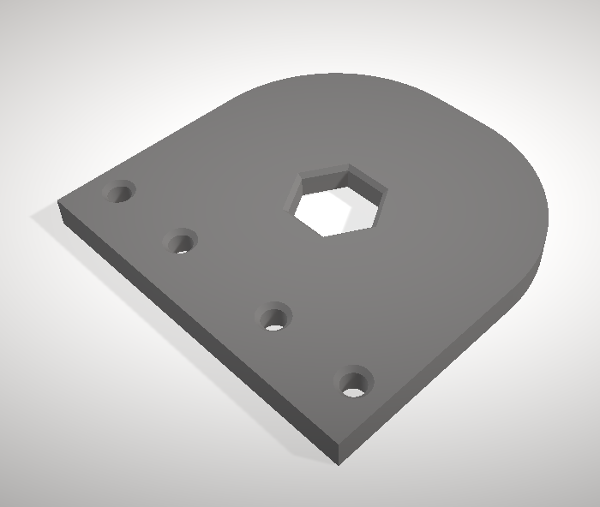
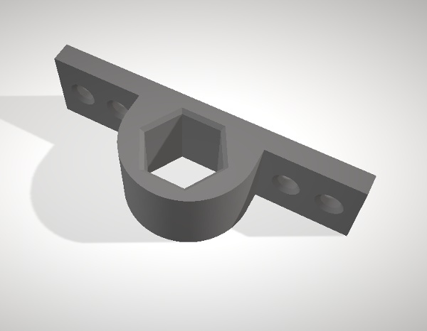
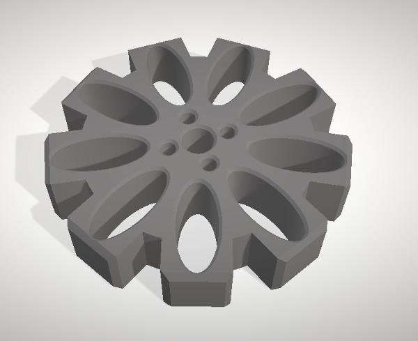
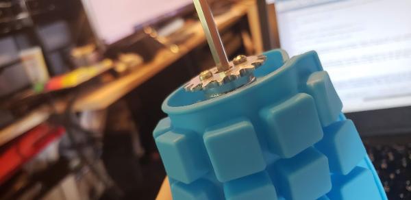
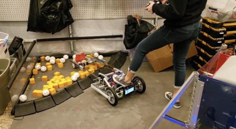
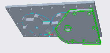
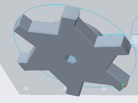
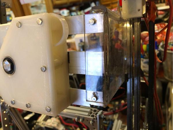
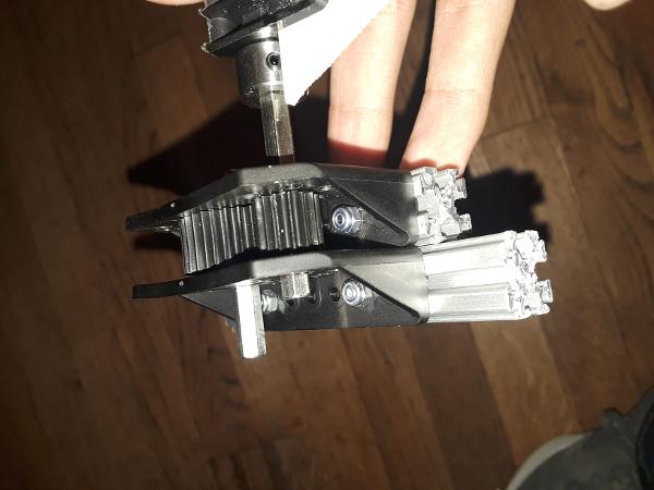
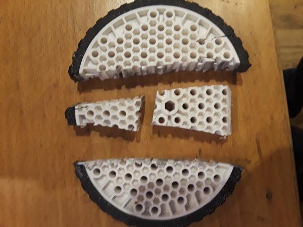
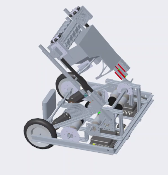
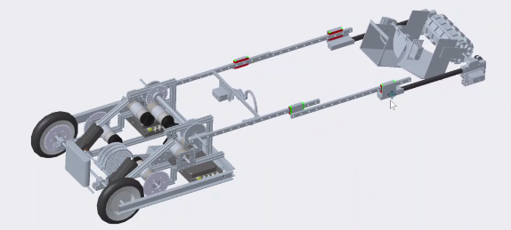
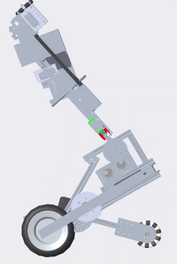
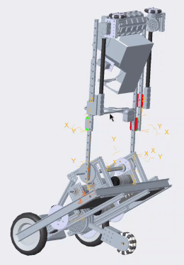
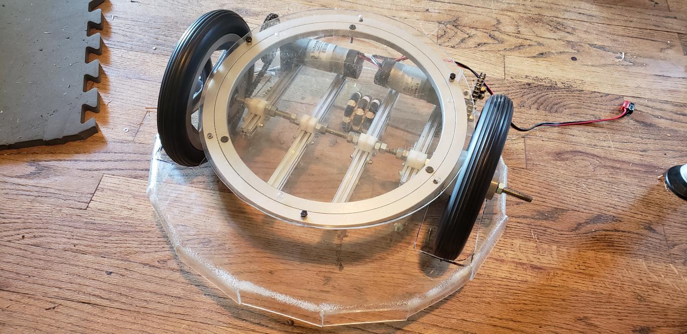
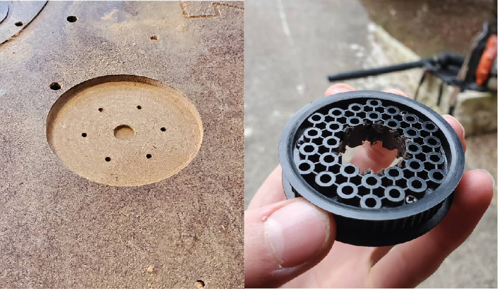
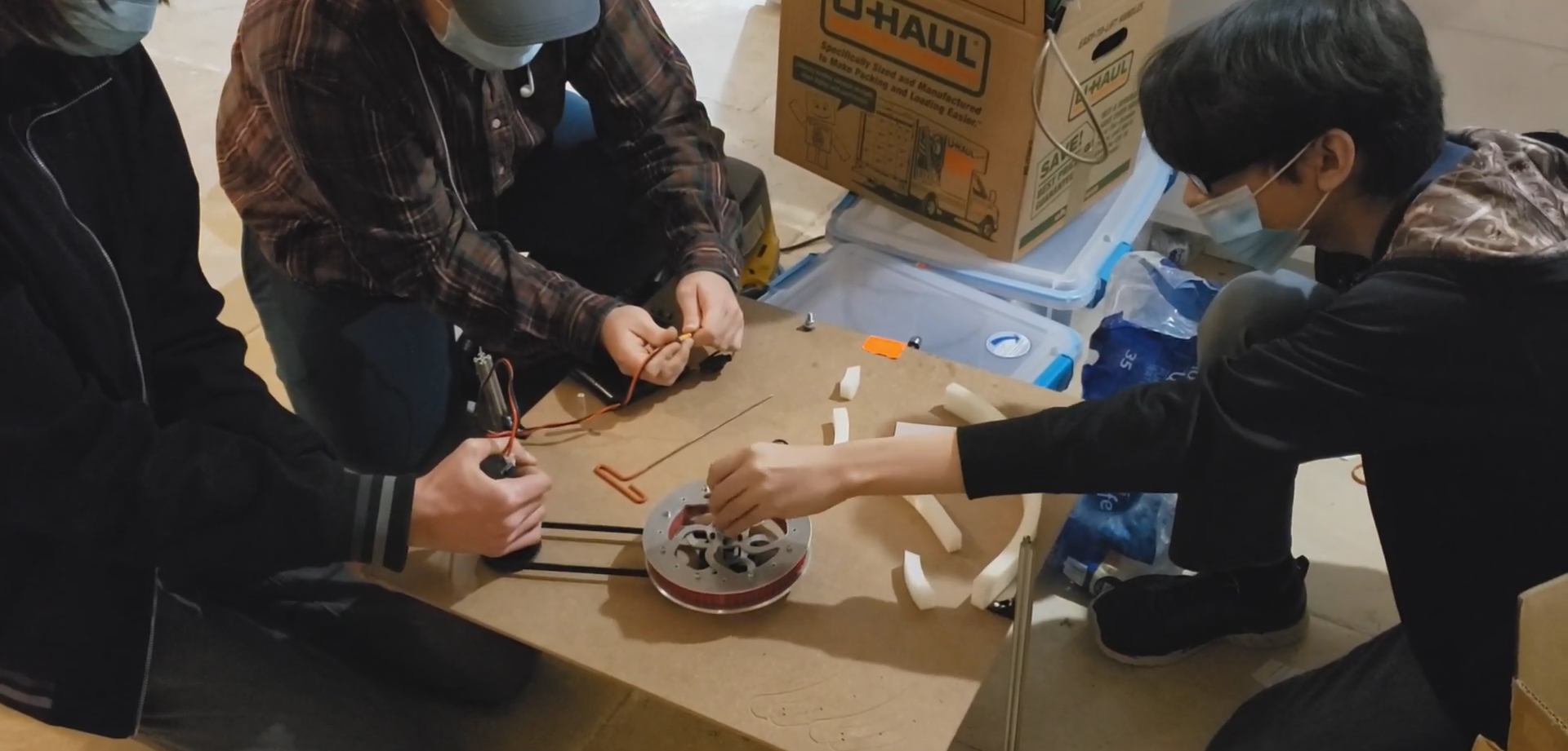
    Our first step was to switch out the back wheels on it to elf-sized bicycle wheels, allowing us to take on the mightiest of curbs and motorize it. To attach the wheels, a four foot or so cylinder of threaded steel was inserted in holes on either side of the cart. Two slots were cut out in the bottom for the wheels and they were eventually slid on, but not after 3D printed mounts for sprockets were attached to the wheels, enabling us to gear them in a one to one ratio with the sprocket attached to the motors, which consisted of two SIM motors commonly found on FRC robots.

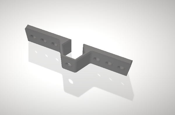
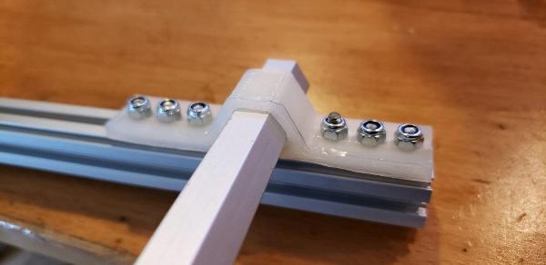
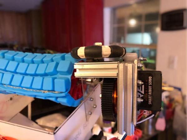
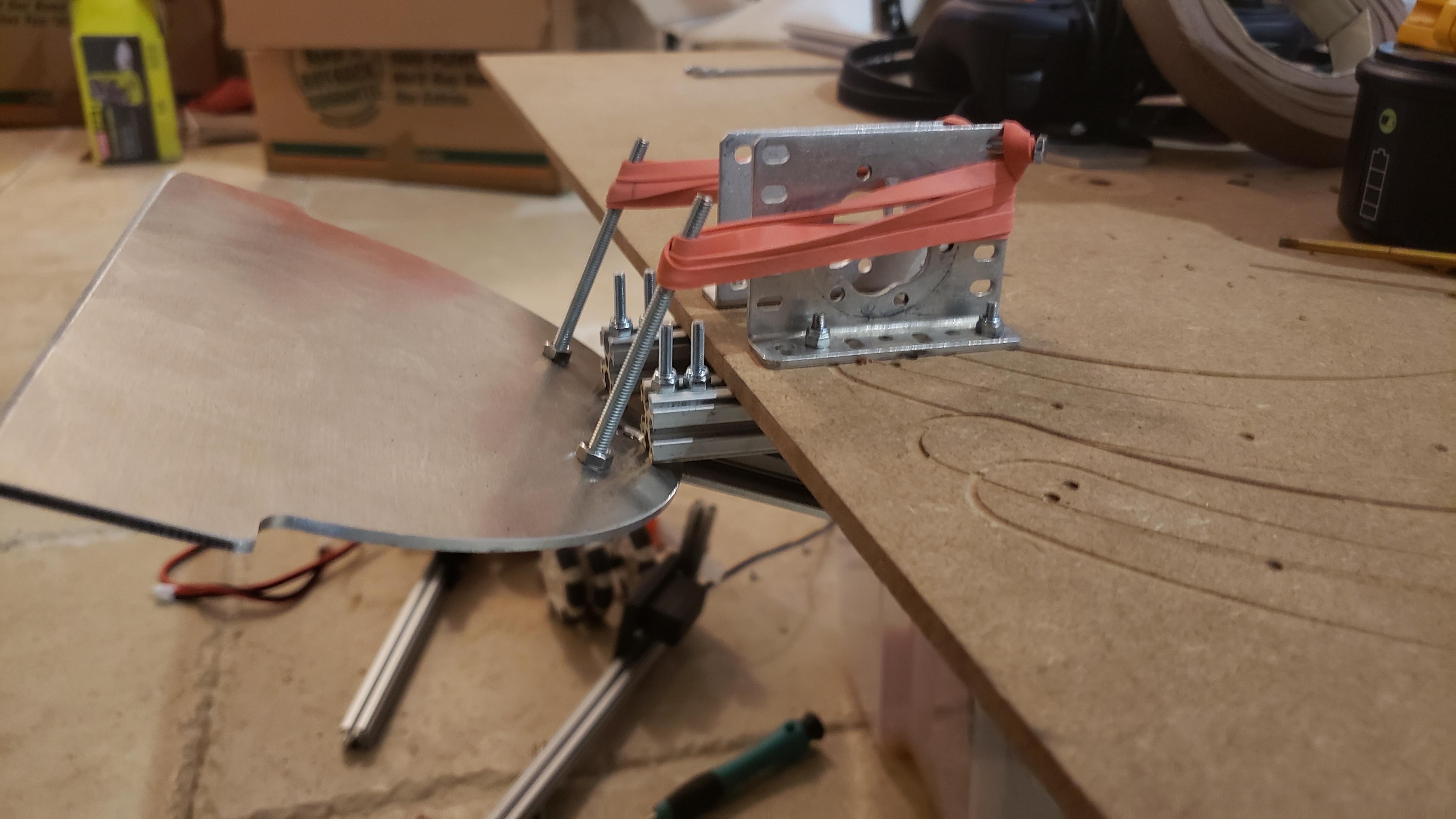
    Before we used SIM motors, we attempted to power the cart using two Tetrix motors which were geared for speed but, due to load, barely moved at all. Besides a lack of power, they also tended to come out of alignment, causing a terrible noise and causing the cart to come to a stall. This was quickly scrapped. To mount the motors, we used two pieces of aluminum bars and bolted them to the motors, then screwed them to the floor of the cart, aligned with the wheels. We chained them together and got about powering the system. We got two 12-volt batteries and chained them in parallel so as to not overload the system, and hooked them up to a REV hub. Then, we ran them through a switch and breaker combination. We connected the motors to the rev hub and once we had it all powered up, we put some code on it and decided to take it for a spin.

    It worked surprisingly well, so we went back in and put the finishing touches on the base of Cart Bot, mainly attaching the top back on so we could put stuff on top of it, and cutting holes for switches and wires to run through, to make it as slick as possible. We added a power distribution station to assist with the charging and distribute current to any device we decided to charge on the cart. We will eventually hook this up to our new and improved battery box we plan on making in the few spare moments we’ll have this season, just a quick quality of life improvement to make future competitions go smoothly.

    Next Steps

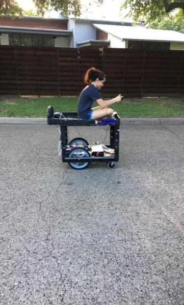
    Our cart box isn’t done yet, as we intend to make a mount for a solar panel, which we will be able to charge the cart during the downtime in competitions (only if there’s a good window we can park it next to). The cart wasn’t just about having a cool new and improved cart that we don’t have to push (which it is), it also was a test of our engineering skills, taking things that never should have been and putting them together to make something that we will utilize every competition. We learned so much during this experience, I for one learned how to wire something with two batteries as not to destroy the system, as for everyone else, I can’t speak for all but I think we learned a very important lesson on the dangers of electricity, mainly from the height of the sparks from an accidental short that happened along the way. Despite this, the cart came out great and moves smoother than I ever could have hoped. The thing is a real blast and has provided a lot of fun for the whole team, because yes, it is ridable. We predict the speed it’s set at is only a fifth of its full potential speed, and since it already goes a tad on the fast end we don't intend to boost it anymore while there’s a rider on it. Overall, the project was a success, and I’m personally very proud of my work as I’m certain everyone else is too. Come to see it at our table, I really think it’s worth it.

    Designing Wheel Mounts

    Designing Wheel Mounts By Justin

    Task: Create wheel mounts for our Mini-Mecanum chassis

    Today, we modeled two possible designs for mini-mecanum wheel mounts. The purpose of the mounts is to hold a churro or hex shaft in place to mount mecanum wheels to. The first design was a 6cm by 6cm square with rounded edges that was 5mm thick. A hexagon was removed from the center to hold the churro that supports the mecanum wheel. This design, when printed on low infill, allowed the churro to rotate when enough force was applied. We modeled this design off of the wheel mounts on Kraken and Garchomp; the only differences are the size and material. Because we will be 3D printing these mounts, material efficiency is very important. This mount design used a lot of material to make a prototype, meaning a finished stable mount would need even more material to prevent the churro or hex shaft from slipping.

    Taking these problems into account, we designed a different way to mount the wheels. The new version can mount underneath a REV Rail and hold the shaft or churro perpendicular to the rail. This design uses much less infill than the previous one because of how small the mount is, and because the REV Rail also acts as support to prevent the churro or shaft from spinning. The mount also allows the mini-mecanum wheels to be mounted as close to the frame as possible, which can help make the robot more compact. This design will allow us to easily mount mini-mecanums to our frame, while using minimal filament and taking up very little space.


    Next Steps

    We need to build the full mini-mecanum robot to judge whether these designs will fully work.

    Corn-Cob Intake

    Corn-Cob Intake By Ethan and Abhi

    Task: Design an intake system unique for balls

    Right now, we're working on a static-deposit system. The first part of this system is having an intake mechanism that passively differentiates the balls and cubes, reducing complexity of other parts of the design. Thus, we created the corn-cob intake.

    First, we bought ice-cube trays. We wanted a compliant material that would grip the particles and be able to send them into a larger delivery mechanism.

    Then, we designed a wheel which' spokes would fit into the holes on an ice cube tray, allowing the tray to stay static while still being compliant in a cylindrical shape. Then, we can put axle hubs through the center of the wheel, allowing us to mount the wheels on a hexagonal shaft. Then, we can mount a sprocket on that, allowing the bar to be rotated for intake. This bar is mounted at the height of the balls, not blocks, so we can passively sort the minerals in-action.

    Next Steps

    We need to mount this on our robot and design a way to deliver the field elements. We're also going to go into more detail on the ice cube mounts in a later blog post.

    Another Design Bites the Dust

    Another Design Bites the Dust By Ethan

    Task: Discuss a new rule change

    At one point, we were thinking about creating a "mining facility" robot that stays static within the crater and delivers the blocks into the mining depot. In our eyes, it was legal as it would hold as many blocks as possible inside the crater but only deliver two at a time outside. It would be super-efficient as we would be able to stay within the crater, and not need to move.

    However, fate has struck. Earlier this week, we received this message:

    The rule limiting control/possession limits of minerals has been updated to indicate that robots may _temporarily_ hold more than 2 minerals in the crater, but must shed any excess over prior to performing any other gameplay activities (which would include scoring).
    says that "Robots In a Crater are not eligible to Score Minerals". Per the definitions of "In" and "Crater", if _any_ portion of a Robot is in the vertical area above the crater (extending from the field walls to the outside edge of the Crater Rim), then scoring a Mineral results in a Major Penalty.
    says that Robots may not obstruct another Robot's path of travel in the area between the Lander and a Crater for more than 5 seconds.

    This means that we couldn't do a static mining facility as we cannot score within the crater. Since we'd have a portion of the robot always in the crater, the existence of our robot would be a major penalty.

    Next Steps

    So, we need to rethink our robot. We still want to create a semi-static robot, but we need to redesign the intake portion.

    Mining Base 2.0

    Mining Base 2.0 By Ethan

    Task: Rethink our static robot idea

    So, our dream this year is to create a static robot. Last week, we found out about a rule change that would prevent our mining robot from staying within the crater. Naturally, we found a way around this, leading us to the Mining Base 2.0.

    The robot will be fixed under the lander's hooks, and have a horizontal and vertical linear slide attached to it. The horizontal linear slide would reach over the crater walls and pick up the silver balls, and shoot them up towards the lander. On the lander, our vertical linear slide would create a backboard that would allow the balls to fall into the lander. This wouldn't violate the rules as we wouldn't be in the crater. And, it would give us the benefit of having an extremely high-scoring robot.

    Next Steps

    We need to start on the designs of this robot, but to do this, we first need to create a working chassis.

    Issues with Driving

    Issues with Driving By Karina

    Task: Get ready for Regionals

    Regionals is coming up, and there are some driving issues that need to be addressed. Going back to November, one notable issue we had at the Conrad qualifier was the lack of friction between Bigwheel's wheels and the field tiles. There was not enough weight resting on the wheels, which made it hard to move suddenly.

    Since then many changes have been made to Bigwheel in terms of the lift. For starters, we switched out the REV extrusion linear slide for the MGN12H linear slide. We have also added more components to intake and carry minerals. These steps have fixed the previous issue if we keep the lift at a position not exceeding ~70 degrees while moving, but having added a lot of weight to the end of the slide makes rotating around the elbow joint of Bigwheel problematic. As you can see below, Bigwheel's chassis is not heavy enough to stay grounded when deploying the arm (and so I had to step on the back end of Bigwheel like a fool).

    Another issue I encountered during driver practice was trying to deposit minerals in the lander. By "having issues" I mean I couldn't. Superman broke as soon as I tried going into the up position, and this mechanism was intended to raise Bigwheel enough so that is would reach the lander. Regardless of Superman's condition, the container for the minerals was still loose and not attached to the servo. Consequently, I could not rotate the lift past the vertical without dropping the minerals I had collected.

    Next Steps

    To run a full practice match, Superman and the container will need to be fixed, as well as the weight issue. Meanwhile, I will practice getting minerals out of the crater.

    Latch Model

    Latch Model By Abhi and Justin

    Task: Model and print the Latch

    Early in the season, we made a hook, Although it was durable, it required a higher amount of precision than we would have liked to have, especially in the rushed last seconds of the endgame. As a result, we designed a latch that is completely 3D printed and placed it on the robot.

    This is the general model of it fit together (excluding left panel). The panels in the front are there to guide the latch into place when extending upwards from the ground.

    This wheel represents what actually does the latching. When sliding upwards, there are two wheels that twirl in opposite directions and slot into the lander bracket. We attached a smaller piece to this to tension with a rubber band allowing us to move up into the bracket but not back down.

    Next Steps

    We actually mounted this onto the robot and it seems to hold its own weight. However, the mounting was done very weirdly so we need to find a definite place for this system before we use it in auto or end game.

    Intake Omnis

    Intake Omnis By Ben

    Task: Add omnidirectional wheels to intake arm

    We need to add omniwheels to the intake arm to allow the arm to rest on the ground, while still maintaining the necessary height for collecting the minerals. If the height is too low, the minerals wouldn't be able to move through the intake. If the intake was too high, it wouldn't be able to grip onto the minerals and pull them through. We decided to use omnidirectional wheels as they would allow us to drive forward and backwards with the arm extended.Our first challenge was finding space on the intake arm to attach the wheels. We had a few options:

    • Attach the wheels parallel to the arm
    • To do this, we would have to have a "u" shaped component, which we could mount off of a threaded extrusion, then attach that to the servo mount.
    • Mount the wheel perpendicular to the arm
    • This would give the same degree of maneuverability. To attach this, we would have to use an elbow bracket and attach that to an extrusion at a 90° angle.
    Both of these present a similar challenge, leaving enough room for the intake to function properly. With about 2.5in. to work with, we mounted the wheel perpendicular with a 1.75 in. extrusion. We threaded the extrusion and used an elbow bracket to mount the wheel; this ensures the strength of the wheel. This left about 0.5in. between the wheel and the "corn on the cob" intake.

    Image of wheel attached to intake arm

    Next Steps

    Our next steps are to perform testing on the wheels to determine if they are durable and low enough, and improve the performance of the robot. One issue that may arise is rubbing against the gears, as they may shift over prolonged usage, along with twisting of the extrusion.

    Latch V.3.5 Assembly

    Latch V.3.5 Assembly By Ben

    Task: Assemble the V.3.5 latch and attach to the robot

    We assembled the fourth version of the latch today. Some of the improvements on this latch include using bigger bearings and thrust bearings inside. This latch is designed to be stronger and more reliable. After cleaning the parts and trimming some edges, we assembled the pieces. Upon assembly, we discovered an issue: the gears required a different amount of pressure to catch the lock. If left untreated, it could result in the robot falling off the hook. We determined the root of this problem was that the locking mechanism on the right gear was shorter than the left. To fix this, we trimmed a few millimeters off the piece that provides tension on the left gear to match that of the right gear.

    Latch attached to polycarbonate brackets.

    Next Steps

    We will need to perform various tests on the latch to determine if the height is correct, if the latch can support the robot, ease of latching and unlatching, and consistency. We plan to test our robot this Saturday at the DISD STEM Expo, which will provide an opportunity to practice latching.

    Fixing Mineral Dropper Components

    Fixing Mineral Dropper Components By Jose and Evan

    Task: Fix any issues with the mineral dropper

    At the STEM expo we saw a clear issue with the mineral dropper: it is very poorly geared and doesn't deposit minerals well. A quick look at the gear configuration revealed that the gears were attached in a poor manner such that there was a lot of gear skippage. To remedy this, we attached a gear-box to the dropper to keep the gears interlocked.

    The way the mineral dropper works is by having a wire attached to the shaft that turns the release be pushed when the robot hits the lander. The wire is attached with a portion of a gear custom cut for the job.

    We need to upgrade to a thicker wire for more reliable shaft rotations. After doing so we needed a different wire holder and we chose a REV wheel. After cutting it and drilling bigger holes to accommodate the new wire we needed to attach it all to the shaft for the mineral release.

    Next Steps

    We need to finish bending the wire and test its ability to open the mineral release when contacting the lander.

    Big Wheel Articulations

    Big Wheel Articulations By Abhi

    Task: Summary of all Big Wheel movements

    In our motion, our robot shifts multiple major subsystems (the elbow and Superman) that make it difficult to keep the robot from tipping. Therefore, through driver practice, we determined the 5 major deployment modes that would make it easier for the driver to transition from mode to mode. Each articulation is necessary to maintain the robot's center of gravity as its mode of operation shifts.

    The position seen above is called "safe drive". During normal match play, our drivers can go to this position to navigate the field quickly and with the arm out of the way.

    When the driver control period starts, we normally navigate to the crater then enter the intake position shown above. From this position, we can safely pick up minerals from the crater.

    From the intake position, the robot goes to safe drive to fix the weight balance then goes to the deposit position shown above. The arm can still extend upwards above the lander and our automatic sorter can place the minerals appropriately.

    During the end game, we enter a latchable position where our hook can easily slide into the latch. After hooked on, our robot can slightly lift itself off the ground to hook.

    At the beginning of the match, we can completely close the arm and superman to fit in sizing cube and latch on the lander.

    As you can see, there is a lot of articulations that need to work together during the course of the match. By putting this info in a state machine, we can easily toggle between articulations. Refer to our code snippets for more details.

    Next Steps

    At this point, we have 4 cycles in 1 minute 30 seconds. By adding some upgrades to the articulations using our new distance sensors, we hope to speed this up even more.

    Up-to-Date Bigwheel Model

    Up-to-Date Bigwheel Model By Justin

    Task: Finish the Bigwheel model

    Updating the Bigwheel model to the robot’s current configuration was a challenge. The new linear slides are not standard parts, so we had to model them from scratch. There was some cleaning up that was needed on the drivetrain of the model. This was mainly attaching floating motors to motor mounts and axles to bearings. These were mainly cosmetic changes, but they help define the purpose of the different parts of the drivetrain. We also updated the intake assembly to our current ice cube tray intake. The structure of the intake was easy to model but the ice cube tray gave us some trouble with its unique shape and pattern. The ratchet latching system was a failure, so a new hook model was needed. The main issue with this was that we custom forged our new hook, so there was some difficulty in getting the model to accurately represent the capabilities of the hook. Another challenge was the mineral storage system. This is made from polycarb pieces and has many unique pieces, so arranging the pieces to accurately show the flow of minerals was difficult.

    In addition to updating the model, we also learned how to show the different movements of the robot with the model. Mechanical constraints were added to allow certain parts to slide or rotate. The one problem we had with this was that there were no limitations to how far something could slide or rotate, so many parts of the model would disconnect and be left floating. After some research, a solution was found. Zero points were created for each moving part and minimum and maximum movement limits were added. Some parts that now can move on the robot are the wheels, superman arm, hook, and linear slides. This allows us to not only show the movement of the robot, but also the limitations of its parts, which can help us visualize new solutions to our remaining problems.

    Next Steps

    Our next step is to wait for more build changes, so we can keep updating the model. Another addition we might make is making stress maps of the robot in different configurations to see where parts might fail. This has been an ongoing challenge of keeping the model accurate when the robot gets updated or rebuilt, and now we finally have a finished model and ready robot for regionals.

    Intake Speed

    Intake Speed By Karina

    Task: Analyze efficiency of our intake system

    A big part of our redesign is improving our intake system. To see where some of the errors may lie, we took detailed videos of our robot intaking silver and gold minerals from a side view, one mineral at a time. We measured the time between when the intake first made contact with the mineral, and when the mineral was directly underneath the rotating icecube tray, and therefore in our control, using LoggerPro video analysis.

    Silver Minerals
    TrialΔt (s)
    10.733
    20.466
    31.233
    41.934
    50.766
    60.634
    70.600
    80.466
    92.133
    100.700
    Gold Minerals
    TrialΔt (s)
    10.234
    20.532
    30.300
    40.533
    50.533
    60.300
    71.433
    80.567
    90.800
    100.433

    On average, silver mineral intake took 0.967s and gold mineral intake took 0.567s, meaning our intake was more efficient at gold mineral intake. Looking at Big Wheel intake frame by frame revealed faults in our intake. Intaking gold minerals went smoothly. For silver minerals, however, the slack in the ice cube tray resulted in it losing its grip on the mineral multiple times before the mineral was firmly grasped. This is likely the result of frictional forces struggling to overcome the elastic force of the flexible icecube tray pushing outwards. In trial 4, for example, our intake lost its grip on the mineral 4 times before it could be considered in our control.

    Next Steps: Redesign Intake Mechanism

    We are assembling a subteam of builders to take on the challenge of designing a new intake system. Some issues we'll have to address include:

    • The slack in the center of the corn-on-the-cob intake

    • The silver minerals slipping on the sorter
    • We'll have to have what changes will be made to our current design. (E-147, Intake Update)

    Reverse Articulations

    Reverse Articulations By Abhi

    Task: Summary of Icarus Movements

    In post E-116, I showed all the big wheel articulations. As we shifted our robot to Icarus, we decided to change to a new set of articulations as they would work better to maintain the center of gravity of our robot. Once again, we made 5 major deployment modes. Each articulation is necessary to maintain the robot's center of gravity as its mode of operation shifts.

    The position seen above is called "safe drive". During normal match play, our drivers can go to this position to navigate the field quickly and with the arm out of the way. In addition, we use this articulation as we approach the lander to deposit.

    When the driver control period starts, we normally navigate to the crater then enter the intake position shown above. From this position, we can safely pick up minerals from the crater. Note that there are two articulations shown here. These show the intake position both contracted and extended during intake.

    During the end game, we enter a latchable position where our hook can easily slide into the latch. After hooked on, our robot can slightly lift itself off the ground to hook. This is the same articulation as before.

    At the beginning of the match, we can completely close the arm and superman to fit in sizing cube and latch on the lander. This is the same articulation as before.

    These articulations were integrated into our control loop just as before. This allowed smooth integration

    Next Steps

    As the final build of Icarus is completed, we can test these articulations and their implications.

    Connecting the Hook to a Servo

    Connecting the Hook to a Servo By Karina

    Task: Connect the hook to a servo

    When attaching the hook to the servo, it was very important that the configuration gave the hook its widest possible range of motion. The open position needed to as far back retracted as possible for an easier lander dismount, and the closed position had to be closed enough so that our robot would not fall off the lander in competition.

    The hook was forged prior to its attachment, of course, so the mechanism had to account for the overextension of the end opposite the hook past the horizontal. To solve this problem, a L-bracket was mounted onto the end of the hook.

    The closed position was easier. The servo rotated approximately 180 degrees (its full range of motion being from 899 to 2100) into the closed position.

    Next Steps: Intake

    Now that the hook system is completed, all that's left is to test it and then mount the intake.

    Test Driving New Robot

    Test Driving New Robot By Ben, Jose, and Trey

    Task: Test the "Robot in 2 Days" robot

    Today we were able to drive test our "robot in 2 days" robot. We used our robot from the previous season, Icarus, as our alliance partner. Jose and Trey drove several matches. They were able to score around 40 points consistently. This was a relatively high number considering Icarus was only used as a push bot (it hasn't been adapted to this season's challenge). Jose was able to stack the Stones with precision and accuracy. Because of this, he was also able to do it efficiently. We determined the height of the arm was perfect for the robot, but it could use some finer tuning and adjustments. The hook, which was used to move the foundation, worked well too. One issue we encountered was the loosening of a chain on the front right wheel. Even though it was a simple fix, it did cost several points, as the robot was more challenging to control.

    We were also able to test our robot with our sister team's (Iron Core) robot. Their robot was essentially a push bot too, but provided different challenges for our driver. The core bot was smaller, yet harder to maneuver, especially for newer drivers. This resulted in a loss of points and difficulty operating smoothly. Eventually, both drivers figured it out and were able to score 25-30 points consistently.

    Iron Reign's robot stacks a Skystone while Iron Core's robot pushes a Stone.

    Next Steps

    We will continue to test our robot and fine-tune the arm, chassis, and intake design based on performance. We will also monitor the wheels to ensure they remain adequately attached, to avoid them loosening again.

    TomBot Progress

    TomBot Progress By Karina, Justin, and Trey

    Task: Start assembling the TomBot chassis

    Today we made some progress on our round robot. We moved the rev rails and big wheels on the Bigwheel chassis to be able to fit inside the polycarb circle that we previously made. These movements gave us a good idea of where to position the rev rails, but the wheels were too close to the edge of the circle, to the point where cutting rectangular slots for the wheels would extend the slots outside of the edge of the circle. To correct this, we decided to first cut the slots, then adjust the wheel distance on the old chassis to fit the cuts.

    To cut the slots we first needed to make a template to map out where to cut. We did this on a circular piece of cardboard the same size as the polycarb. After two attempts at aligning the rectangles, we transferred the template onto the polycarb and cut them out with a jigsaw. We planned to round the edges of the rectangular slots to match the shape of the wheels, but an error during the cutting process caused only the outside edges of the rectangles to be rounded.

    Next we needed to mount the rev rail chassis to the polycarb circle and adjust the wheels to fit the new slots. One problem with the chassis is that the rev rails were positioned so that the wheels would sit towards the rear of the robot. After repositioning the rev rails, we marked and drilled holes, then mounted the chassis to the polycarb. TomBot now has the 2 big wheels

    Next steps:

    We need to add the 2 sets of omni wheels to the front and back of the robot to keep the base flat. We should build a basic wheel mount and design a 3d printed mount. The printed mount would be able to flex to soften to force of the robot on the chassis. The motors also need to be chained to the wheels.

    1/16 Build Progress - The first rings fly

    1/16 Build Progress - The first rings fly By Trey, Cooper, Aaron, Paul, Bhanaviya, and Jose

    Task: Continue developing the ring launcher and do preliminary testing

    Today we continued to further our progression on our ring launcher, finally getting to do some preliminary testing to see what the design might do. For starters, we started to get some of the walls off of the 3d printer which was the first piece of our flywheel launcher barrel design that started to come into real life. We also modified the pulley for the flywheel with the CNC that would eventually be used in the final construction. We had to do this because we want to be able to use our REV motors and driving belts to move the non-REV wheel. In order to make sure that we could do this we set up a machining path that would remove an inner circle of material from a standard pulley so that we can put bearings through it.

    The machining of the pulley is actually fairly simple. All we did was set up a path that would mill a cylinder out of the pulley. What was more complicated was what we had to do before that since you can’t mount the pulley on the CNC since it doesn’t lie flat. Instead, we modeled and CNCed a divot for the pulley to fit into along with some holes for screwing the pully to the CNC. You can see both the divot and the final product above. This operation isn’t that difficult on the machine since it’s just plastic and wood but this is the first time that we have had to mill a divot to machine a part which is what makes it notable.

    Then we put what we had together for the first time on a sheet of particleboard and spun up the wheel to see if we could even get a ring moving. We did get some success and the rings did launch several feet but we did have a few problems. Mainly that the walls were being held in place by people so they were moving and we couldn’t get enough grip on the rings. However, actually assembling the flywheel in housing will solve this problem. Honestly, we weren’t looking for problems in the first place though. This event would fall more under team bonding because we really just wanted to see a ring fly. We put in a lot of work and it was quite inspiring to see the ring actually move.

    Next Steps

    We still have a lot more manufacturing ahead of us. We still need to finalize the model and the CAM of all 3 of the plates in the barrel and 3d print more parts. We also still need to assemble and think about how we are going to get the rings into the launcher which will come and bite us in the butt at some point. For now, it was nice to see some progress as well as the first rings fly.

    Build Progress 1/30

    Build Progress 1/30 By Trey, Justin, and Jose

    Task: assemble different intake prototypes

    Today we worked on different intake systems to place the rings in the launcher. We finished our first prototype for a belt type intake and lift. The 3d printed belt was able to slide rings along a vertical piece of polycarb to place rings into the launcher. The speed of the motor and belt makes this one of our quickest intake and delivery prototypes. Our other prototype was a spatula shaped "intake" that would scoop up disks, and flip them upwards into a basket on top of the launcher. We used aluminum CNC'd into a curved spatula that would perfectly fit around the disks to ensure an accurate launch. Rubber bands pull the spatula upward, where it hits stoppers and launches the rings upwards. This prototype created semi consistent flips, but it was hard to gauge how far down to pull the spatula to give a desired launch height. A problem with this method is the many different factors that can be changed to give an optimal launch. Different launch angles, distances from the launcher, rubber band tensions and lengths. This flipper would involve a lot of experimentation that would result in mostly failures. This method also requires a lot more driver skill to scoop up the relatively small disks.

    We also tested our fully assembled launcher - the Ringslinger 9000 - with working code. We wanted to measure how consistent our launches were by shooting multiple rings at a target and measuring the furthest distance between impact points. We used flour on a flat surface to show where the rings were hitting, then circled the clusters for our trials to get an approximate radius of error. We found that our launches were mostly consistent within a small radius, but had outliers that were hitting the exact same outer lying spot. This indicates a consistent flaw with our launcher and requires a closer look at how it moves and launches the rings. We also repeated this test by identifying where the rings tended to cluster when they had been launched beyond the length of the goal-post - even though the Ringslinger 9000 was not supposed to launch rings at such a height, identifying where it tended to cluster after landing also allowed us to evaluate its general launch patterns and accuracy.

    Next Steps:

    The belt system can easily grab disks and brings them to the other end of the ramp very quickly. While it works well when we test it with our hands, we need to create a rigid structure to connect the belt and ramp, which will be mounted on the chassis. This will allow us to see how the belt will need to pivot to grab rings, and if our current belt still maintains grip without human assistance. We will also take a closer look at our launcher to see what's different about our outlier launches.

    Ringevator Overview

    Ringevator Overview By Trey

    Task: Describe the construction and development of the Ringevator intake

    This year we have done a lot of work on intakes and launchers. The purpose of this post is to go over the function and overall design and build of the Ringevator intake. It doesn’t go too far in-depth so if you are looking for something more specific I would recommend that you look at specific posts discussing different parts of our design but if not you are in the right place.

    Build Breakdown:

    The construction of the Ringevator is moderately complex. It consists of a custom belt, two axels, a motor, a pivot, a base, and some elastics. The belt is custom modeled and printed in NinjaFlex. The design is based on the belt seen in one of our previous robots, Kraken, which competed in 2018. It has flaps that do the work of pulling in the rings and holes that are used by sprockets to drive the belt. The holes are the exact size and space apart to be fitted onto the sprockets on the drive axels which are attached to the base. The base is a simple H design that used to be in between the sprockets but now sits so that the sprockets are inside to make mounting easy. The axels are driven by one motor attached by a belt on the base of the robot.

    As you can see in the photo above, the belt assembly base and the robot base have a pivot between them. The purpose of this pivot is to make picking the rings much easier. Normally you would have to pick a ring up horizontally and then turn it to a vertical orientation which is what we need but instead, the pivot allows for the belt assembly to walk over rings. This means that when the intake reaches a ring, the movement of the belt causes the mechanism to open and consume the whole ring. Since only one side of the ring is being pulled up by the belt, it is flipped vertically and travels up the rest of the mechanism and out the top. The elastics make sure that the belt keeps in contact with the ring at all times. The only other thing that is apart of the design is a guide ramp on the inside made of heat-bended polycarbonate. You can see a photo of this ramp below along with the intake before it was attached to the robot on a pivot.

    Testing:

    We tested the Ringevator multiple times throughout its life to make sure that it will work. It gets a good grip on the rings and is able to pull them up most of the time. We still need to iron out a few tensioning issues with the elastics to make it more consistent but other than that it works well based on our tests so far which are few and far between. More testing will come.

    Improvements:

    The design didn’t start out this well though, we made several improvements since the start. For starters, the whole pivot idea was a mistake, to begin with; however, we discovered while doing preliminary tests that the belt walking over rings was a feature, not a defect. We realized that picking up rings without the pivot would be far more difficult and that was the spark for the design we have now. We also suffered some grip issues with the polycarbonate ramp which wanted to grip the rings too much and hindered the ability of the intake. We fixed this with some friction-reduced tape and now it works well. The design is still in its baby stages so we haven’t found a lot of problems but we will eventually and we are excited to address them.

    Next Steps:

    We are working right now on dialing in the shooter to make it more consistent and also testing a 1:1 motor to see how it compares to the 1:3 motor in terms of accuracy. We are also being posed with a challenge unlike any other challenge we have faced this season which is taking what we made when we were developing intakes and making a system that can feed into the shooter. This is going to prove a challenge because of the size of the shooter and the fact that it can be rotated or tilted to any angle. The challenge may be large but we are a worthy opponent.

    Making the Ringevator Legal

    Making the Ringevator Legal By Trey and Paul

    Task: Make the Ringevator legal so we can use it in competition

    We’re at the point now where we have a lot of our systems ready to be put on the robot, but we have to face another big challenge, which is making everything legal. Since the robot is a circle, we don’t exactly have any space to put an intake in the sizing cube. We can take advantage of the hypotenuse of the box by putting our equipment in the corners but then we raise the problem of height. This is because the Ringevator was never actually built to be permanently attached to the robot.

    We built the Ringevator as a prototype that harnessed the abilities of all of our previous models without their problems. However, with time closing in, it became apparent that the ringevator would have to be on the robot regardless of what we think. In order to do this, we had to shorten the assembly by about 2.5 inches and somehow pull the assembly inside more. With only a few builders being able to join us at any particular time, this proved to be a challenge.

    Two things needed to happen to make the robot even close to legal. The first was that the front would have to be chopped off, spitting the front Omni wheel assembly in two. And the second was actually shortening the ringevator which meant shortening the belt. The first part was easily accomplished by modeling two new Omni wheel bases for the front and surgically removing the front of the robot with a hacksaw. This was accomplished in the span of two days. After this was done, Paul also chopped the top of the ringevator off. The last piece was the belt.

    The problem with the belt was that I was the only one who knew how to shorten it and I was stuck at home for the next few days. So after Paul was done with the robot surgery, he swung by my house at 3 AM and dropped the belt off in my mailbox. The next morning, I marked off about 5 inches or 5 flaps of the intake, printed a new rig for the welding, cut, and welded the belt into a shorter configuration with my own tools. Then to get the belt back to the robot, we thought about getting a courier to deliver it but instead, I showed up the next day with the new belt and it was assembled onto the robot. After all of that, the robot was still not legal. The reason why it wasn’t legal is because we used bulky REV extrusions as sides since they are easy for prototyping. Since those rails are thick it just barely falls out of the sizing cube. So we had to detach the whole assembly for our next competition.

    Next Steps

    We would have liked to cut the assembly down more at this point but we couldn’t because we had already pushed the limits of its size. Our next step is to completely redesign the whole intake system. We knew this was going to have to happen at some point but we didn’t think it was going to be this soon. In order to make the intake legal, we have to CNC all of the parts. And I think that’s the kind of challenge Iron Reign is built for.

    UTD Qualifier Build Post Mortem

    UTD Qualifier Build Post Mortem By Trey

    Task: Review our failure of rushed build leading up to the UTD qualifier

    As discussed in the post "Making the Ringevator Legal" there was a lot of rushed build leading up to this qualifier. As a recap of that post, the Ringevator was too wide and too tall to be legal, so we had to cut off the front of the robot, split the omni wheels, shorten the assembly, and shorten the belt. For more information, read that post. So with all of this change leading up to the competition, one would expect that it all worked out.

    Alas, it did not. By the end of the raised build, the robot was still not legal by any means. In fact, the ringevator had to be removed so that we could actually run matches with a legal robot. This, however, is not the end. Even though the robot may not be legal, the judges still respected the development we displayed in our journal and portfolio. We demonstrated real development in innovative systems that I suppose resonated with the judges because we were awarded the Inspire award. Ordinarily, any team would see this as a big accomplishment but the builders at IronReign were restless. We failed our goals. The end objective with building a good robot is to score high amounts of points and that’s the one thing we didn’t do.

    At the very least we did learn quite a bit from the situation. Firstly, the troubles we had with the ring transfer from intake to outtake demonstrated that the pancake flipper was not a good idea. Such a path for ring transfer would be cool but a challenge too large for the coders. Besides, we already have put so much into the ringevator. Abandoning it now would be reckless. We also discovered that another pivot point at the bottom would be vital to the ring transfer. At the moment this is just a REV core hex motor but something more advanced would be helpful. There is also the added possibility of adding a slide to the bottom of the intake which paired with the current pivots, would make the intake far more versatile and clear of the spin of the turntable, which gets caught. There is still much thinking to be done in this department. Finally, the last thing we learned is that the ringevator would need to be remade in a fully custom, aluminum version to make it fit in the sizing cube. This will be a large feat but if we can do it, we will have points when our next qualifier rolls around.

    Next Steps

    We’re going to need to do a lot more before our robot scores real points. I admire our progress but we still have a long way to go. We need to step up on driver practice, reevaluate the ringevator, and start thinking about a final version of the robot. What comes immediately next is modeling and redesigning the ringevator to lose any bulk in the system so it can fit on the robot. I hope that those new developments will allow us to run matches next competition.

    A Prerequisite Chassis to Robot In 3 Days

    A Prerequisite Chassis to Robot In 3 Days By Trey, Cooper, and Aaron

    Task: Build a robot that can be adapted to any challenge

    The challenge reveal is going to be quite soon. In the weeks leading up to the challenge reveal we began to wonder if there was anything we could do that would make our transition from preseason to prototyping any better. And obviously, there are many things we could do that would make our work easier when the time comes to see the new challenge. Mainly, we were thinking that since we do a robot in three days when the challenge gets revealed, it would be beneficial to have a robot chassis that could be used in most challenges and be adapted to the specifics of this year’s challenge. A robot like this should be easily maneuverable and have an arm or subsystem capable of interacting with ordinary objects. That’s where the idea for this robot came from.

    N-bot is the solution to this problem. The idea for N-bot was that we should have a chassis that can drive over elements and manipulate them within the walls of the robot. In order to do this, we created a robot in the shape of a lower case n that can drive over objects. Ideally, the next step would be to give it an arm that can manipulate anything it can drive over; however, we did not have time to complete this. Instead, what we ended up with was a chassis in the shape of a lowercase n.

    For wheels on this robot, we decided that mecanum wheels would be the best choice since we would be able to move in all directions on the field with them and position ourselves accurately over objects. Those four wheels are chained to motors and paired together in wall-shaped blocks that are linked together on top by 4 structural extrusions. The overall shape of the robot appears to be sturdy; however, it is actually quite flimsy. Linking two halves of a robot with only 4 beams on top is not a great idea if you’re looking for a rock-solid design. Instead, our robot tends to flex and shake but that’s ok because those issues are manageable. We sacrificed the structural integrity of our robot for ease of adaptation to challenge specific tasks.

    Next Steps:

    The next steps for this project are clear: we wait for the challenge to be revealed and then we adapt N-bot to that challenge with any number of additional subsystems. We are planning on only using this robot for our robot in 3 days challenge and nothing else so none of the subsystems we produce will be used at any other point in the year.

    Chassis Brainstorming

    Chassis Brainstorming By Trey, Cooper, and Shawn

    Task: Build a robot that can be adapted to any challenge

    The new challenge is upon us and with a new challenge comes new robot designs. This year we have found that we are going to need to focus on the chassis of our robot more than ever. This is because the barrier to the warehouse is an important obstacle that we want to be able to climb or get around in order to score. The drawings and notes depicted below are the unfiltered notes that I took shortly after the discussions we had about chassis designs.

    Next Steps:

    The next steps here are to pick one or two of these designs and run with them. We need to build some prototypes of these fast before the first scrimmage or competition. I think the ones we are most likely to prototype in the coming weeks are the Flipin' tank, the tricycle, and the Flippin' bot. We're excited to see where these designs take us.

    October 29th Screamage Overview

    October 29th Screamage Overview By Georgia, Aarav, Anuhya, Trey, Gabriel, and Leo

    Screamage at Marcus High School Overview

    Today, Iron Reign attended the Screamage at Marcus High School to play a couple of practice matches. This event allowed us the opportunity to better understand the game flow and further develop a strategy, finally get some drive practice, and point out any flaws in the robot and its design to help improve the next iteration of TauBot.

    Initially, we were faced with a lot of structural issues regarding the build of the robot. The wire connection on the arm had to be properly secured to ensure that cables did not get tangled or caught whenever the crane extended, and minor modifications to the chassis were required to properly secure the LED Panels to the robot.

    Then came the software troubleshooting. The robot struggled to properly drive without drifting and our drivers needed minor modifications to the mapping of the buttons to streamline gameplay. However, we were able to get tons of solid drive practice at the practice field and were able to consistently score multiple cones on all 3 levels of the poles by the end of the scrimmage. We also utilized our memory functions to help automate the pickup and drop-off process and taught our drivers how to best use those capabilities.

    Then came the actual practice matches, and let's just say, they did not proceed as smoothly as expected. Our lack of drive practice was evident, as we often dropped cones short of the poles and were barely able to score successfully. At one point, we managed to pick up around 6-7 cones, but only succeeded in scoring 1-2 cones onto the actual pole. Evidently, this is something that will need to be addressed before the first league meet.

    Robot reliability also proved to be a major concern and created a lot of issues during gameplay as our robot would often break down during the game, rendering it useless and incapable of doing anything. After ramming our robot into a junction during gameplay, part of the polycarb chassis cracked where the screws were attached to the Rev Rails, which also locked up our front set of Omni wheels that we used for stability. We managed to restore the robot to a usable state, but the cracked polycarbonate will remain until we build the new robot. These issues continued to plague our robot, and during a match, the axle holding up the crane dislodged from the motor mount, which caused the entire crane to shut down mid-match, and led to us replacing the axle and the screws used to secure it.

    Next Steps

    The first thing we need to do is shave off part of the arm so our robot will fit within the sizing cube. Secondly, we need to redesign the configuration of the LED panel and battery mount, bottom battery wire, and the arm wire holder, so the wires do not hinder the robot's movement and ability to perform. Thirdly, we must find a way to keep the left motor from slipping out of its mount. We also need to adjust the height of the front Omni wheels, using spacers to allow for more movement and prevent them from locking up. Finally, we need to add polycarb plates to the chassis to prevent furthur damage.

    Meeting Log 11/8

    Meeting Log 11/8 By Gabriel and Leo

    Task: Preparing the Robot for the Upcoming League Meet

    General Fixes:

    The LED battery holder from the previous meeting snapped, requiring us to rebend and make a new gate for the LED Battery holder from scratch, which took a bit of time. In addition to this, all the set screws on the robot for the shaft collars and the pulley systems, as well as using threadlocker on the right motor mount in order to keep the right motor from shifting out of place and causing the chain to fall off the gear. This also solved the problem of the chain not fully aligning with the gear, causing a gradual stray of the straight pathing.

    3D Modeling a New Wire Holder:

    As discussed previously, the current iteration of the wire holder for the arm extension made of cardboard isn’t practical, and so Leo worked on a 3D model for the new version of the wire holder. This version addresses the wire getting caught upon on the corners of the holder as well as a more durable design as cardboard is not good at keeping it’s shape, and will more easily fit over the 2 motors.