Articles by tag: control

Articles by tag: control

    Swerve Drive Experiment

    Swerve Drive Experiment By Abhi

    Task: Consider a Swerve Drive base

    Last season, we saw many robots that utilized a swerve drive rather than the mecanum drive for omnidirectional movement. To further expand Iron Reign's repertoire of drive bases, I wanted to further investigate this chassis. Swerve was considered as an alternative to swerve because of its increased speed in addition to the maneuverability of the drive base to allow for quick scoring due to its use of traction wheels at pivot angles. Before we could consider making a prototype, we investigated several other examples.

    Among the examples considered was the PRINT swerve for FTC by team 9773. After reading their detailed assembly instructions, I moved away from their design for many reasons. First, the final cost of the drive train was very expensive; we did not have a very high budget despite help from our sponsors. If this drive train was not functional or if the chassis didn't make sense to use in Rover Ruckus, we would have almost no money for an alternate drive train. Also, they parts used by 9773 involved X-rail rather than extrusion rail from REV. This would cause problems in the future as we would need to redesign the REVolution system for X-rail.

    Another example was from team 9048 which appeared to be more feasible. Because they used REV rail and many 3D printed parts, this was a more feasible prototype. Because they didn't have a parts list, we had the find the rough estimate of cost from the REV and Andymark websites. Upon further analysis, we realized that the cost, though cheaper than the chassis of 9773, would still be a considerable chunk of our budget.

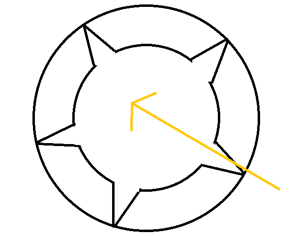
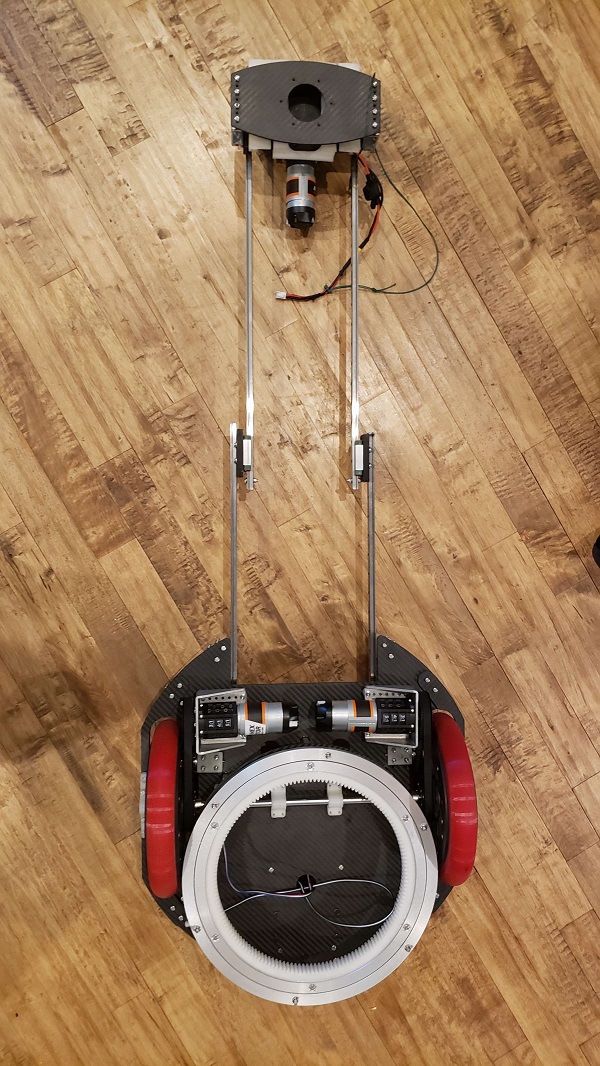
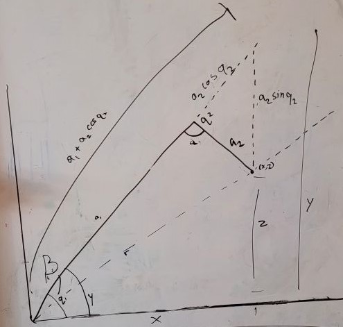
    At this point it was evident most swerve drives being used are very expensive. Wary of making this investment, I worked with our sister team 3734 to create a budget swerve with materials around the house. A basic sketch is listed below.

    Next Steps

    Scavenge for parts in the house and Robodojo to make swerve modules.

    Swerve Drive Prototype

    Swerve Drive Prototype By Abhi and Christian

    Task: Build a Swerve Drive base

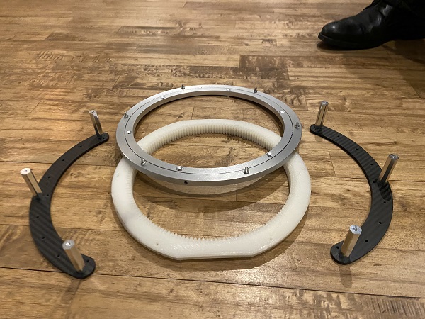
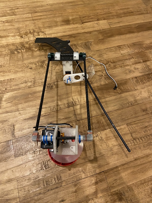
    Over the past week, I worked with Christian and another member of Imperial to prototype a drive train. Due to the limited resources. we decided to use Tetrix parts since we had an abundance of those. We decided to make the swerve such that a servo would turn a swerve module and the motors would be attached directly to the wheels.

    Immediately we noticed it was very feeble. The servos were working very hard to turn the heavy module and the motors had trouble staying aligned. Also, programming the chassis was also a challenge. After experimenting further, the base even broke. This was a moment of realization. Not only was swerve expensive and complicated, we also would need to replace a module really quickly at competition which needed more resources and an immaculate design. With all these considerations, I ultimately decided that swerve wasn't worth it to use as a drive chassis at this time.

    Next Steps

    Consider and prototype other chassis designs until Rover Ruckus begins.

    Position Tracking

    Position Tracking By Abhi

    Task: Design a way to track the robot's location

    During Relic Recovery season, we had many problems with our autonomous due to slippage in the mecanum wheels and our need to align to the balancing stone, both of which created high error in our encoder feedback. To address this recurring issue, we searched for an alternative way to identify our position on the field. Upon researching online and discussing with other teams, we discovered an alternative tracker sensor with unpowered omni wheels. This tracker may be used during Rover Ruckus or beyond depending on what our chassis will be.

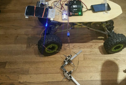
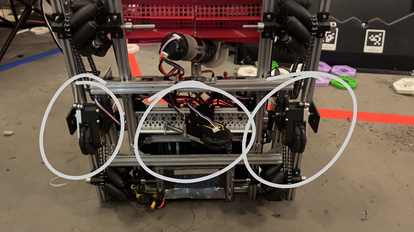
    We designed the tracker by building a small right angular REV rail assembly. On this, we attached 2 omni wheels at 90 degrees to one another and added axle encoders. The omni wheels were not driven because we simply wanted them to glide along the floor and read the encoder values of the movements. This method of tracking is commonly referred to as "dead wheel tracking". Since the omnis will always be touching the ground, any movement will be sensed in them and prevents changes in readings due to defense or drive wheel slippage.

    To test the concept, we attached the apparatus to ARGOS. With some upgrades to the ARGOS code by using the IMU and omni wheels, we added some basic trigonometry to the code to accurately track the position. The omni setup was relatively accurate and may be used for future projects and robots.

    Next Steps

    Now that we have a prototype to track position without using too many resources, we need to test it on an actual FTC chassis. Depending on whether or not there is terrain in Rover Ruckus, the use of this system will change. Until then, we can still experiment with this and develop a useful multipurpose sensor.

    Replay Autonomous

    Replay Autonomous By Arjun

    Task: Design a program to record and replay a driver run

    One of the difficulties in writing an autonomous program is the long development cycle. We have to unplug the robot controller, plug it into a computer, make a few changes to the code, recompile and download the code, and then retest our program. All this must be done over and over again, until the autonomous is perfected. Each autonomous takes ~4 hours to write and tune. Over the entire season, we spend over 40 hours working on autonomous programs.

    One possible solution for this is to record a driver running through the autonomous, and then replay it. I used this solution on my previous robotics team. Since we had no access to a field, we had to write our entire autonomous at a competition. After some brainstorming, we decided to write a program to record our driver as he ran through our autonomous routine and then execute it during a match. It worked very well, and got us a few extra points each match.

    Using this program, writing an autonomous program is reduced to a matter of minutes. We just need to run through our autonomous routine a few times until we're happy with it, and then take the data from the console and paste it into our program. Then we recompile the program and run it.

    There are two parts to our replay program. One part (a Tele-op Opmode) records the driver's motions and outputs it into the Android console. The next part (an Autonomous Opmode) reads in that data, and turns it into a working autonomous program.

    Next Steps

    Our current replay program requires one recompilation. While it is very quick, one possible next step is to save the autonomous data straight into the phone's internal memory, so that we do not have to recompile the program. This could further reduce the time required to create an autonomous.

    One more next step could be a way to easily edit the autonomous. The output data is just a big list of numbers, and it is very difficult to edit it. If we need to tune the autonomous due to wear and tear on the robot, it is difficult to do so without rerecording. If we can figure out a mechanism for editing the generated autonomous, we can further reduce the time we spend creating autonomous programs.

    Rover Ruckus Brainstorming & Initial Thoughts

    Rover Ruckus Brainstorming & Initial Thoughts By Ethan, Charlotte, Kenna, Evan, Abhi, Arjun, Karina, and Justin

    Task: Come up with ideas for the 2018-19 season

    So, today was the first meeting in the Rover Ruckus season! On top of that, we had our first round of new recruits (20!). So, it was an extremely hectic session, but we came up with a lot of new ideas.

    Building

    • A One-way Intake System

    • This suggestion uses a plastic flap to "trap" game elements inside it, similar to the lid of a soda cup. You can put marbles through the straw-hole, but you can't easily get them back out.
    • Crater Bracing
    • In the past, we've had center-of-balance issues with our robot. To counteract this, we plan to attach shaped braces to our robot such that it can hold on to the walls and not tip over.
    • Extendable Arm + Silicone Grip

    • This one is simple - a linear slide arm attached to a motor so that it can pick up game elements and rotate. We fear, however, that many teams will adopt this strategy, so we probably won't do it. One unique part of our design would be the silicone grips, so that the "claws" can firmly grasp the silver and gold.
    • Binder-ring Hanger

    • When we did Res-Q, we dropped our robot more times than we'd like to admit. To prevent that, we're designing an interlocking mechanism that the robot can use to hang. It'll have an indent and a corresponding recess that resists lateral force by nature of the indent, but can be opened easily.
    • Passive Intake
    • Inspired by a few FRC Stronghold intake systems, we designed a passive intake. Attached to a weak spring, it would have the ability to move over game elements before falling back down to capture them. The benefit of this design is that we wouldn't have to use an extra motor for intake, but we risk controlling more than two elements at the same time.
    • Mechanum
    • Mechanum is our Ol' Faithful. We've used it for the past three years, so we're loath to abandon it for this year. It's still a good idea for this year, but strafing isn't as important, and we may need to emphasize speed instead. Plus, we're not exactly sure how to get over the crater walls with Mechanum.
    • Tape Measure
    • In Res-Q, we used a tape-measure system to pull our robot up, and we believe that we could do the same again this year. One issue is that our tape measure system is ridiculously heavy (~5 lbs) and with the new weight limits, this may not be ideal.
    • Mining
    • We're currently thinking of a "mining mechanism" that can score two glyphs at a time extremely quickly in exchange for not being able to climb. It'll involve a conveyor belt and a set of linear slides such that the objects in the crater can automatically be transferred to either the low-scoring zone or the higher one.

    Journal

    This year, we may switch to weekly summaries instead of meeting logs so that our journal is more reasonable for judges to read. In particular, we were inspired by team Nonstandard Deviation, which has an amazing engineering journal that we recommend the readers to check out.

    Programming

    Luckily, this year seems to have a more-easily programmed autonomous. We're working on some autonomous diagrams that we'll release in the next couple weeks. Aside from that, we have such a developed code base that we don't really need to update it any further.

    Next Steps

    We're going to prototype these ideas in the coming weeks and develop our thoughts more thoroughly.

    Vision Discussion

    Vision Discussion By Arjun and Abhi

    Task: Consider potential vision approaches for sampling

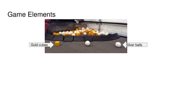
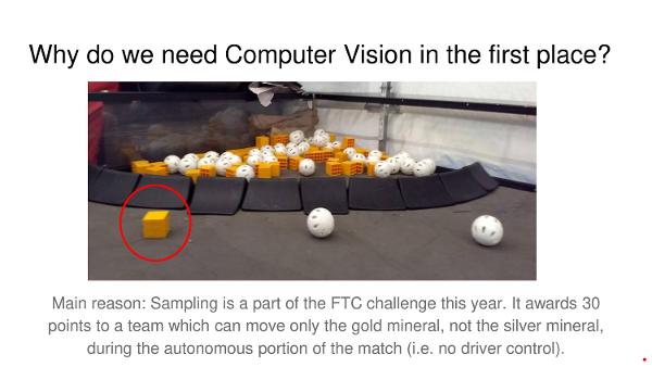
    Part of this year’s game requires us to be able to detect the location of minerals on the field. The main use for this is in sampling. During autonomous, we need to move only the gold mineral, without touching the silver minerals in order to earn points for sampling. There are a few ways we could be able to detect the location of the gold mineral.

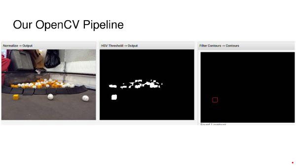
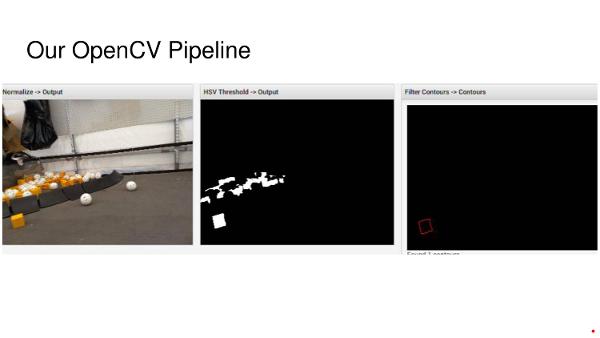
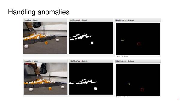
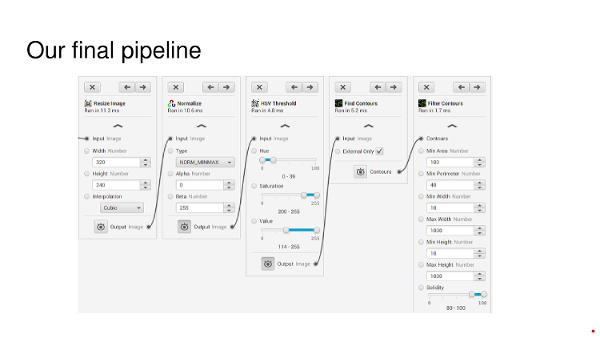
    First, we could possibly use OpenCV to run transformations on the image that the camera sees. We would have to design an OpenCV pipeline which identifies yellow blobs, filters out those that aren’t minerals, and finds the centers of the blobs which are minerals. This is most likely the approach that many teams will use. The benefit of this approach is that it will be easy enough to write. However, it may not work in different lighting conditions that were not tested during the designing of the OpenCV pipeline.

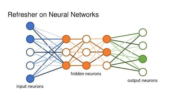
    Another approach is to use Convolutional Neural Networks (CNNs) to identify the location of the gold mineral. Convolutional Neural Networks are a class of machine learning algorithms that “learn” to find patterns in images by looking at large amounts of samples. In order to develop a CNN to identify minerals, we must take lots of photos of the sampling arrangement in different arrangements (and lighting conditions), and then manually label them. Then, the algorithm will “learn” how to differentiate gold minerals from other objects on the field. A CNN should be able to work in many different lighting conditions, however, it is also more difficult to write.

    Next Steps

    As of now, Iron Reign is going to attempt both methods of classification and compare their performance.

    CNN Training

    CNN Training By Arjun and Abhi

    Task: Capture training data for a Convolutional Neural Network

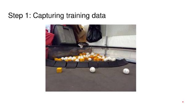
    In order to train a Convolutional Neural Network, we need a whole bunch of training images. So we got out into the field, and took 125 photos of the sampling setup in different positions and angles. Our next step is to label the gold minerals in all of these photos, so that we can train a Convolutional Neural Network to label the gold minerals by learning from the patterns of the training data.

    Next Steps

    Next, we will go through and designate gold minerals. In addition, we must create a program to process these.

    Autonomous Path Planning

    Autonomous Path Planning By Abhi

    Task: Map Autonomous paths

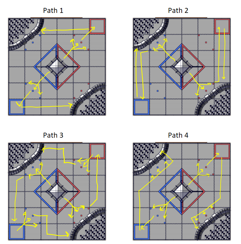
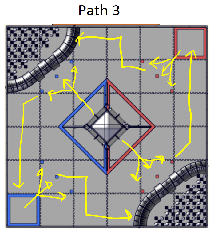
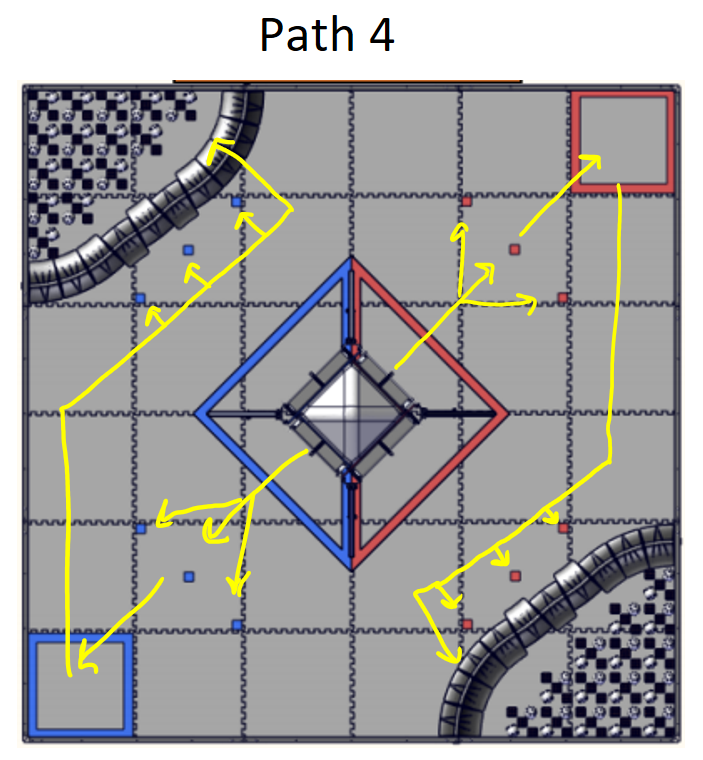
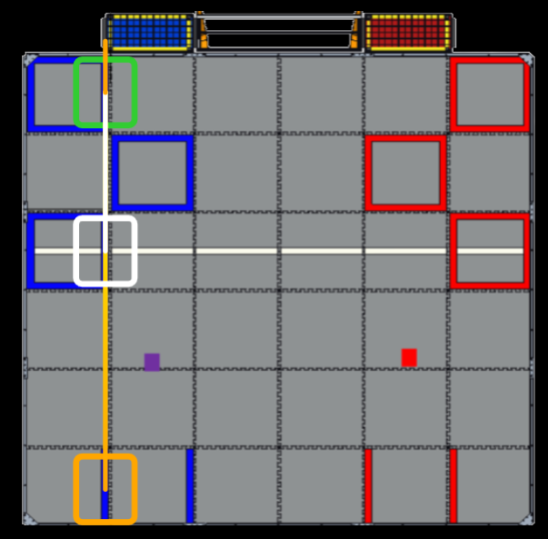
    With the high point potential available in this year's autonomous it is essential to create autonomous paths right now. This year's auto is more complicated due to potential collisions with alliance partners in addition to an unknown period of time spend delatching from the lander. To address both these concerns, I developed 4 autonomous paths we will investigate with to use during competition.

    When making auto paths, there are some things to consider. One, the field is the exact same for both red and blue alliance, meaning we don't need to rewrite the code to act on the other side of the field. Second, we have to account for our alliance partner's autonomous if they have one and need to adapt to their path so we don't crash them. Third, we have to avoid the other alliance's bots to avoid penalties. There are no explicit boundaries this year for auto but if we somehow interrupt the opponent's auto we get heavily penalized. Now, with these in mind, lets look at these paths.

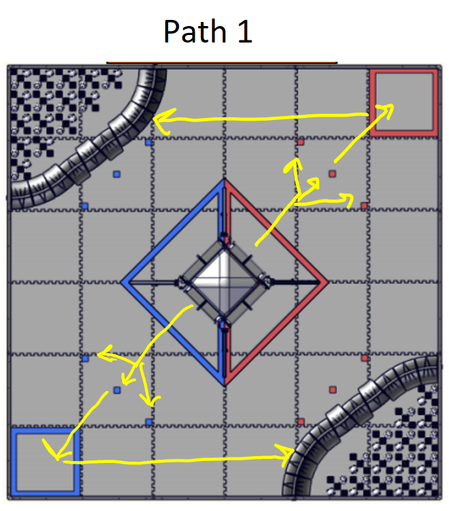
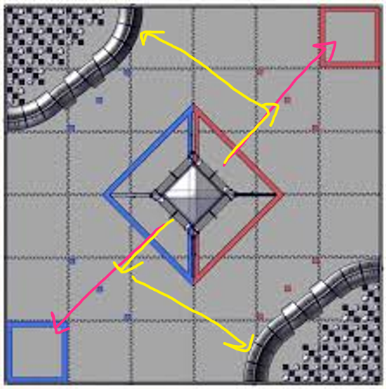
    This path plan is the simplest of all autonomi. I assume that our alliance partner has an autonomous and our robot only takes care of half the functions. It starts with a simple detaching from the lander, sampling the proper mineral, deploying the team marker, and parking in the crater. The reason I chose the opposite crater instead of the one on our nearside was that it was shorter distance and less chance to mess with our alliance partner. The issue with this plan is that it may interfere with the opponent's autonomous but if we drive strategically hugging the wall, we shouldn't have issues.

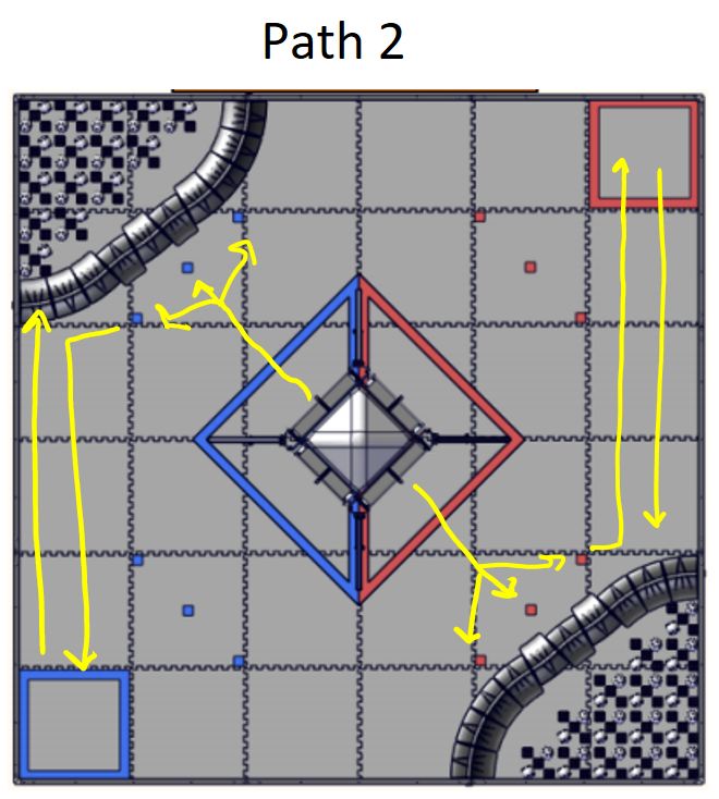
    This path is also a "simple" path but is obviously complicated. The issue is that the team marker depot is not on the same side as the lander, forcing us to drive all the way down and back to park in the crater. I could also change this one to go to the opposite crater but that may interfere with our alliance partner's code.

    This is one of the autonomi that assumes our alliance partners don't have an autonomous and is built for multi-functionality. The time restriction makes this autonomous unlikely but it is still nice to plan out a path for it.

    This is also one of the autonomi that assumes our alliance partners don't have an autonomous. This is the simpler one of the methods but still has the same restrictions

    Next Steps

    Although its great to think these paths will actually work out in the end, we might need to change them a lot. With potential collisions with alliance partners and opponents, we might need a drop down menu of sorts on the driver station that can let us put together a lot of different pieces so we can pick and choose the auto plan. Maybe we could even draw out the path in init. All this is only at the speculation stage right now.

    CNN Training Program

    CNN Training Program By Arjun and Abhi

    Task: Designing a program to label training data for our Convolutional Neural Network

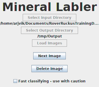
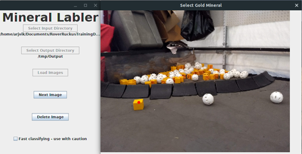
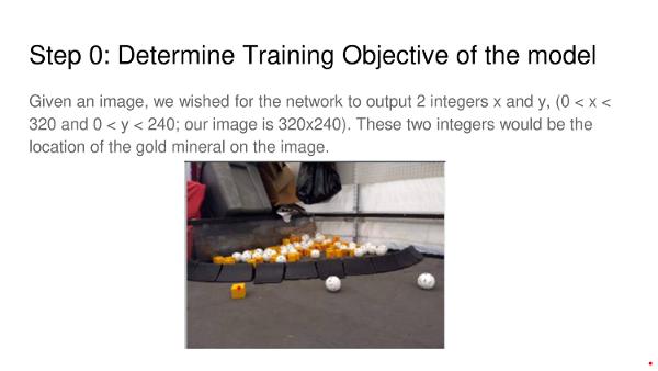
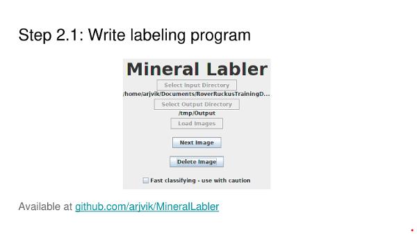
    In order to use the captured training data, we need to label it by identifying the location of the gold mineral in it. We also need to normalize it by resizing the training images to a constant size, (320x240 pixels). While we could do this by hand, it would be a pain to do so. We would have to resize each individual picture, and then identify the coordinates of the center of the gold mineral, then create a file to store the resized image and coordinates.

    Instead of doing this, we decided to write a program to do this for us. That way, we could just click on the gold mineral on the screen, and the program would do the resizing and coordinate-finding for us. Thus, the process of labeling the images will be much easier.

    Throughout the weekend, I worked on this program. The end result is shown above.

    Next Steps

    Now that the program has been developed, we need to actually use it to label the training images we have. Then, we can train the Convolutional Neural Network.

    Labelling Minerals - CNN

    Labelling Minerals - CNN By Arjun and Abhi

    Task: Label training images to train a Neural Network

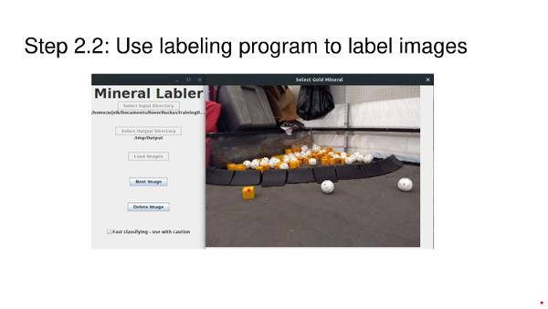
    Now that we have software to make labeling the training data easier, we have to actually use it to label the training images. Abhi and I split up our training data into two halves, and we each labeled one half. Then, when we had completed the labeling, we recombined the images. The images we labeled are publicly available at https://github.com/arjvik/RoverRuckusTrainingData.

    Next Steps

    We need to actually write a Convolutional Neural Network using the training data we collected.

    Upgrading to FTC SDK version 4.0

    Upgrading to FTC SDK version 4.0 By Arjun

    Task: Upgrade our code to the latest version of the FTC SDK

    FTC recently released version 4.0 of their SDK, with initial support for external cameras, better PIDF motor control, improved wireless connectivity, new sensors, and other general improvements. Our code was based on last year's SDK version 3.7, so we needed to merge the new SDK with our repository.

    The merge was slightly difficult, as there were some issues with the Gradle build system. However, after a little fiddling with the configuration, as well as fixing some errors in the internal code we changed, we were able to successfully merge the new SDK.

    After the merge, we tested that our code still worked on Kraken, last year's competition robot. It ran with no problems.

    Developing a CNN

    Developing a CNN By Arjun and Abhi

    Task: Begin developing a Convolutional Neural Network using TensorFlow and Python

    Now that we have gathered and labeled our training data, we began writing our Convolutional Neural Network. Since Abhi had used Python and TensorFlow to write a neural network in the past during his visit to MIT over the summer, we decided to do the same now.

    After running our model, however, we noticed that it was not very accurate. Though we knew that was due to a bad choice of layer structure or hyperparameters, we were not able to determine the exact cause. (Hyperparameters are special parameters that need to be just right for the neural network to do well. If they are off, the neural network will not work well.) We fiddled with many of the hyperparameters and layer structure options, but were unable to fix the inaccuracy levels.

     1
     2
     3
     4
     5
     6
     7
     8
     9
    10
    11
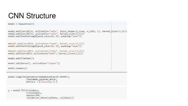
    model = Sequential()
    model.add(Conv2D(64, activation="relu", input_shape=(n_rows, n_cols, 1), kernel_size=(3,3)))
    model.add(Conv2D(32, activation="relu", kernel_size=(3,3)))
    model.add(MaxPooling2D(pool_size=(8, 8), padding="same"))
    model.add(Conv2D(8, activation="tanh", kernel_size=(3,3)))
    model.add(MaxPooling2D(pool_size=(8, 8), padding="same"))
    model.add(Conv2D(4, activation="relu", kernel_size=(3,3)))
    model.add(Conv2D(4, activation="tanh", kernel_size=(1,1)))
    model.add(Flatten())
    model.add(Dense(2, activation="linear"))
    model.summary()
    

    Next Steps

    We have not fully given up, though. We plan to keep attempting to improve the accuracy of our neural network model.

    Rewriting CNN

    Rewriting CNN By Arjun and Abhi

    Task: Begin rewriting the Convolutional Neural Network using Java and DL4J

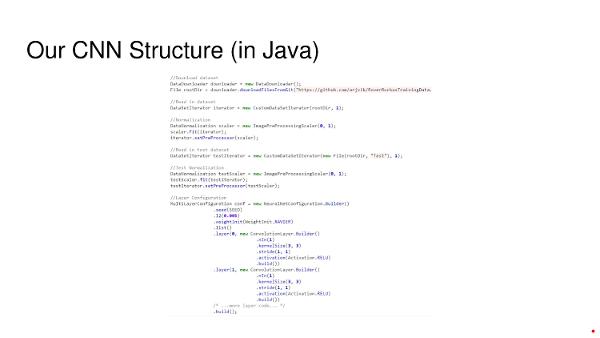
    While we were using Python and TensorFlow to train our convolutional neural network, we decided to attempt writing this in Java, as the code for our robot is entirely in Java, and before we can use our neural network, it must be written in Java.

    We also decided to try using DL4J, a competing library to TensorFlow, to write our neural network, to determine if it was easier to write a neural network using DL4J or TensorFlow. We found that both DL4J and TensorFlow were similarly easy to use, and while each had a different style, code written using both were equally easy to read and maintain.

     1
     2
     3
     4
     5
     6
     7
     8
     9
    10
    11
    12
    13
    14
    15
    16
    17
    18
    19
    20
    21
    22
    23
    24
    25
    26
    27
    28
    29
    30
    31
    32
    33
    34
    35
    36
    37
    38
    39
    40
    41
    java
    		//Download dataset
    		DataDownloader downloader = new DataDownloader();
    		File rootDir = downloader.downloadFilesFromGit("https://github.com/arjvik/RoverRuckusTrainingData.git", "data/RoverRuckusTrainingData", "TrainingData");
    		
    		//Read in dataset
    		DataSetIterator iterator = new CustomDataSetIterator(rootDir, 1);
    		
    		//Normalization
    		DataNormalization scaler = new ImagePreProcessingScaler(0, 1);
    		scaler.fit(iterator);
    		iterator.setPreProcessor(scaler);
    		
    		//Read in test dataset
    		DataSetIterator testIterator = new CustomDataSetIterator(new File(rootDir, "Test"), 1);
    			
    		//Test Normalization
    		DataNormalization testScaler = new ImagePreProcessingScaler(0, 1);
    		testScaler.fit(testIterator);
    		testIterator.setPreProcessor(testScaler);
    		
    		//Layer Configuration
    		MultiLayerConfiguration conf = new NeuralNetConfiguration.Builder()
    				.seed(SEED)
    				.l2(0.005)
    				.weightInit(WeightInit.XAVIER)
    				.list()
    				.layer(0, new ConvolutionLayer.Builder()
    						.nIn(1)
    						.kernelSize(3, 3)
    						.stride(1, 1)
    						.activation(Activation.RELU)
    						.build())
    				.layer(1, new ConvolutionLayer.Builder()
    						.nIn(1)
    						.kernelSize(3, 3)
    						.stride(1, 1)
    						.activation(Activation.RELU)
    						.build())
    				/* ...more layer code... */
    				.build();
    

    Next Steps

    We still need to attempt to to fix the inaccuracy in the predictions made by our neural network.

    Pose BigWheel

    Pose BigWheel By Abhi

    Task: New Pose for Big Wheel robot

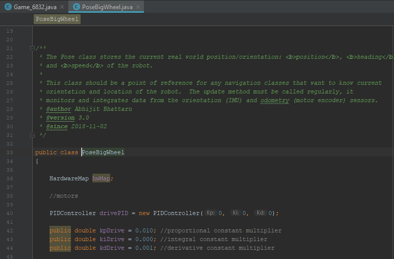
    Historically, Iron Reign has used a class called "Pose" to control all the hardware mapping of our robot instead of putting it directly into our opmodes. This has created cleaner code and smoother integration with our crazy functions. However, we used the same Pose for the past two years since both had an almost identical drive base. Since there wasn't a viable differential drive Pose in the past, I made a new one using inspiration from the mecanum one. Pose will be used from this point onwards in our code to setup.

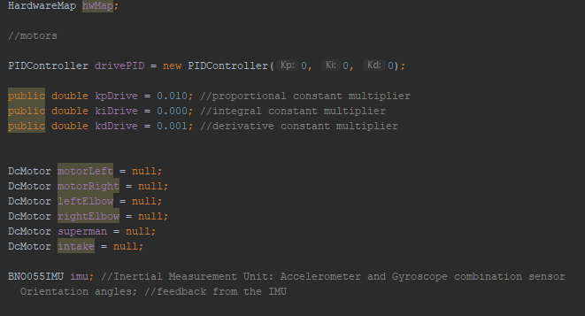
    We start with initializing everything including PID constants and all our motors/sensors. I will skip all this for this post since this is repetitive in all team code.

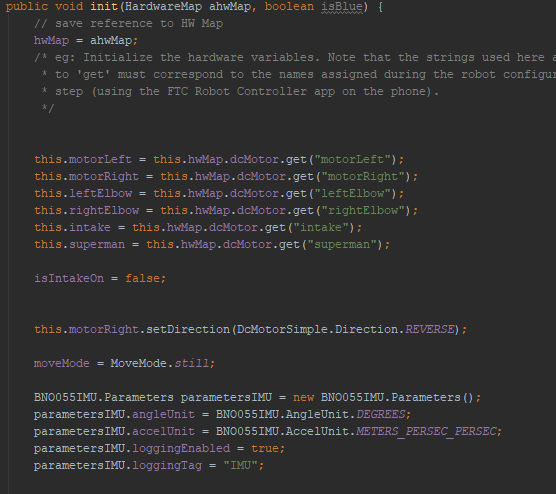
    In the init, I made the hardware mapping for the motors we have on BigWheel right now. Other functions will come in later.

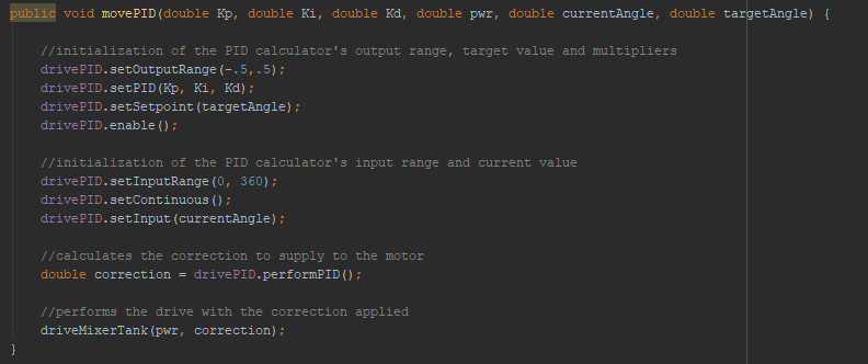
    Here is where a lot of the work happens. This is what allows our robot to move accurately using IMU and encoder values.

    There are a lot of other methods beyond these but there is just a lot of technical math behind them with trigonometry. I won't bore you with the details but our code is open source so you can find the necessary help if you just look at our github!

    RIP CNN

    RIP CNN By Abhi

    Task: Farewell Iron Reign's CNN

    FTC released new code to support Tensorflow and automatically detect minerals with the model they trained. Unfortunately, all of our CNN work was undercut by this update. The silver lining is that we have done enough research into how CNN's work and it will allow us to understand the mind of the FTC app better. In addition, we may retrain this model if we feel it doesn't work well. But now, it is time to bid farewell to our CNN.

    Next Steps

    From this point, we will further analyze the CNN to determine its ability to detect the minerals. At the same time, we will also look into OpenCV detection.

    Code Post-Mortem after Conrad Qualifier

    Code Post-Mortem after Conrad Qualifier By Arjun and Abhi

    Task: Analyze code failure at Conrad Qualifier

    Iron Reign has been working hard on our robot, but despite that, we did not perform well owing to our autonomous performance.

    Our autonomous plan was fairly simple: perform sampling, deploy the team marker, then drive to the crater to park. We planned to use the built-in TensorFlow object detection for our sampling, and thus assumed that our autonomous would be fairly easy.

    On Thursday, I worked on writing a class to help us detect the location of the gold mineral using the built-in TensorFlow object detection. While testing this class, I noticed that it produced an error rather than outputting the location of the gold mineral. This error was not diagnosed until the morning of the competition.

    On Friday, Abhi worked on writing code for the driving part of the autonomous. He wrote three different autonomous routines, one for each position of the gold mineral. His code did not select the routine to use yet, leaving it open for us to connect to the TensorFlow class to determine which position the gold mineral was.

    On Saturday, the morning of the competition, we debugged the TensorFlow class that was written earlier and determined the cause of the error. We had misused the API for the TensorFlow object detection, and after we corrected that, our code didn't spit out an error anymore. Then, we realized that TensorFlow only worked at certain camera positions and angles. We then had to adjust the position of our robot on the field, so that we could.

    Our code failure was mostly due to the fact that we only started working on our autonomous two days before the competition. Next time, we plan to make our autonomous an integral part of our robot, and focus on it much earlier.

    Next Steps:

    We spend more time focusing on code and autonomous, to ensure that we enter our next competition with a fully working autonomous.

    DPRG Vision Presentation

    DPRG Vision Presentation By Arjun and Abhi

    Task: Present to the Dallas Personal Robotics Group about computer vision

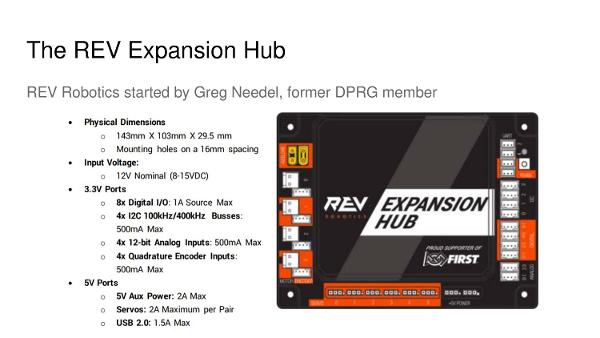
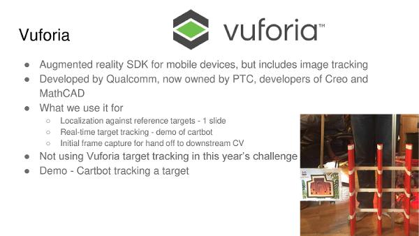
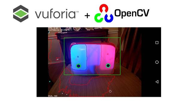
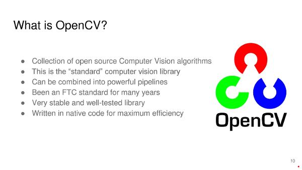
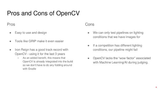
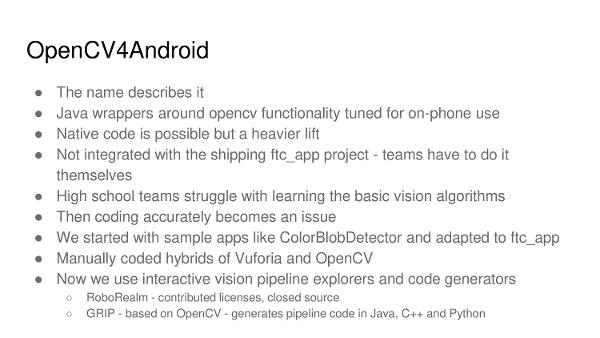
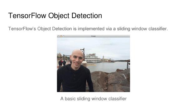
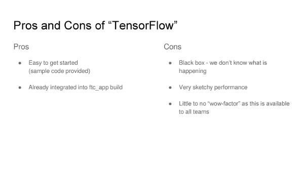
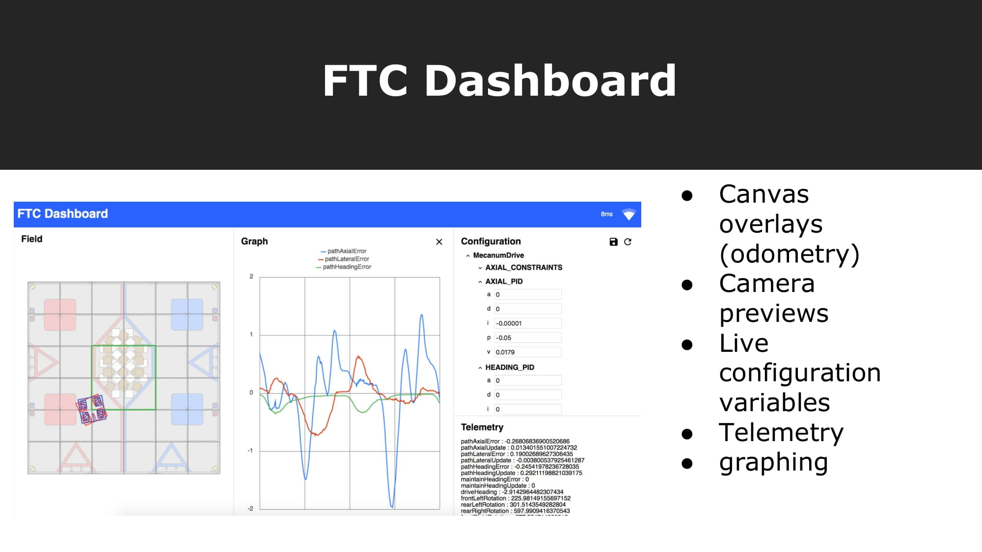
    We presented to the DPRG about our computer vision, touching on subjects including OpenCV, Vuforia, TensorFlow, and training our own Convolutional Neural Network. Everyone we presented to was very interested in our work, and they asked us many questions. We also received quite a few suggestions on ways we could improve the performance of our vision solutions. The presentation can be seen below.

    Next Steps

    We plan to research what they suggested, such as retraining our neural networks and reusing our old training images.

    Refactoring Vision Code

    Refactoring Vision Code By Arjun

    Task: Refactor Vision Code

    Iron Reign has been working on multiple vision pipelines, including TensorFlow, OpenCV, and a home-grown Convolutional Neural Network. Until now, all our code assumed that we only used TensorFlow, and we wanted to be able to switch out vision implementations quickly. As such, we decided to abstract away the actual vision pipeline used, which allows us to be able to choose between vision implementations at runtime.

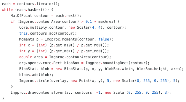
    We did this by creating a java interface, VisionProvider, seen below. We then made our TensorFlowIntegration class (our code for detecting mineral positions using TensorFlow) implement VisionProvider.

    Next, we changed our opmode to use the new VisionProvider interface. We added code to allow us to switch vision implementations using the left button on the dpad.

    Our code for VisionProvider is shown below.

    1
    2
    3
    4
    5
    6
    public interface VisionProvider {
        public void initializeVision(HardwareMap hardwareMap, Telemetry telemetry);
        public void shutdownVision();
        public GoldPos detect();
    }
    ```
    

    These methods are implemented in the integration classes.
    Our new code for TensorflowIntegration is shown below:

     1
     2
     3
     4
     5
     6
     7
     8
     9
    10
    11
    12
    13
    14
    15
    16
    17
    18
    19
    20
    21
    22
    23
    24
    25
    26
    27
    28
    29
    30
    31
    32
    33
    34
    35
    36
    37
    38
    39
    40
    41
    42
    43
    44
    45
    46
    47
    48
    49
    50
    51
    52
    53
    54
    55
    56
    57
    58
    59
    60
    61
    62
    63
    64
    65
    66
    67
    68
    69
    70
    71
    72
    73
    74
    75
    76
    77
    78
    79
    80
    81
    82
    83
    84
    85
    86
    87
    88
    89
    90
    91
    92
    93
    94
    95
    96
    97
    98
    99
    public class TensorflowIntegration implements VisionProvider {
        private static final String TFOD_MODEL_ASSET = "RoverRuckus.tflite";
        private static final String LABEL_GOLD_MINERAL = "Gold Mineral";
        private static final String LABEL_SILVER_MINERAL = "Silver Mineral";
    
        private List<Recognition> cacheRecognitions = null;
      
        /**
         * {@link #vuforia} is the variable we will use to store our instance of the Vuforia
         * localization engine.
         */
        private VuforiaLocalizer vuforia;
        /**
         * {@link #tfod} is the variable we will use to store our instance of the Tensor Flow Object
         * Detection engine.
         */
        public TFObjectDetector tfod;
    
        /**
         * Initialize the Vuforia localization engine.
         */
        public void initVuforia() {
            /*
             * Configure Vuforia by creating a Parameter object, and passing it to the Vuforia engine.
             */
            VuforiaLocalizer.Parameters parameters = new VuforiaLocalizer.Parameters();
            parameters.vuforiaLicenseKey = RC.VUFORIA_LICENSE_KEY;
            ;
            parameters.cameraDirection = CameraDirection.FRONT;
            //  Instantiate the Vuforia engine
            vuforia = ClassFactory.getInstance().createVuforia(parameters);
        }
    
        /**
         * Initialize the Tensor Flow Object Detection engine.
         */
        private void initTfod(HardwareMap hardwareMap) {
            int tfodMonitorViewId = hardwareMap.appContext.getResources().getIdentifier(
                    "tfodMonitorViewId", "id", hardwareMap.appContext.getPackageName());
            TFObjectDetector.Parameters tfodParameters = new TFObjectDetector.Parameters(tfodMonitorViewId);
            tfod = ClassFactory.getInstance().createTFObjectDetector(tfodParameters, vuforia);
            tfod.loadModelFromAsset(TFOD_MODEL_ASSET, LABEL_GOLD_MINERAL, LABEL_SILVER_MINERAL);
        }
    
        @Override
        public void initializeVision(HardwareMap hardwareMap, Telemetry telemetry) {
            initVuforia();
    
            if (ClassFactory.getInstance().canCreateTFObjectDetector()) {
                initTfod(hardwareMap);
            } else {
                telemetry.addData("Sorry!", "This device is not compatible with TFOD");
            }
    
            if (tfod != null) {
                tfod.activate();
            }
        }
    
        @Override
        public void shutdownVision() {
            if (tfod != null) {
                tfod.shutdown();
            }
        }
    
        @Override
        public GoldPos detect() {
            List<Recognition> updatedRecognitions = tfod.getUpdatedRecognitions();
            if (updatedRecognitions != null) {
                cacheRecognitions = updatedRecognitions;
            }
            if (cacheRecognitions.size() == 3) {
                int goldMineralX = -1;
                int silverMineral1X = -1;
                int silverMineral2X = -1;
                for (Recognition recognition : cacheRecognitions) {
                    if (recognition.getLabel().equals(LABEL_GOLD_MINERAL)) {
                        goldMineralX = (int) recognition.getLeft();
                    } else if (silverMineral1X == -1) {
                        silverMineral1X = (int) recognition.getLeft();
                    } else {
                        silverMineral2X = (int) recognition.getLeft();
                    }
                }
                if (goldMineralX != -1 && silverMineral1X != -1 && silverMineral2X != -1)
                    if (goldMineralX < silverMineral1X && goldMineralX < silverMineral2X) {
                        return GoldPos.LEFT;
                    } else if (goldMineralX > silverMineral1X && goldMineralX > silverMineral2X) {
                        return GoldPos.RIGHT;
                    } else {
                        return GoldPos.MIDDLE;
                    }
            }
            return GoldPos.NONE_FOUND;
    
        }
    
    }
    

    Next Steps

    We need to implement detection using OpenCV, and make our class conform to VisionProvider, so that we can easily swap it out for TensorflowIntegration.

    We also need to do the same using our Convolutional Neural Network.

    Finally, it might be beneficial to have a dummy implementation that always “detects” the gold as being in the middle, so that if we know that all our vision implementations are failing, we can use this dummy one to prevent our autonomous from failing.

    OpenCV Support

    OpenCV Support By Arjun

    Task: Add OpenCV support to vision pipeline

    We recently refactored our vision code to allow us to easily swap out vision implementations. We had already implemented TensorFlow, but we hadn't implemented code for using OpenCV instead of TensorFlow. Using the GRIP pipeline we designed earlier, we wrote a class called OpenCVIntegration, which implements VisionProvider. This new class allows us to use OpenCV instead of TensorFlow for our vision implementation.
    Our code for OpenCVIntegration is shown below.

      1
      2
      3
      4
      5
      6
      7
      8
      9
     10
     11
     12
     13
     14
     15
     16
     17
     18
     19
     20
     21
     22
     23
     24
     25
     26
     27
     28
     29
     30
     31
     32
     33
     34
     35
     36
     37
     38
     39
     40
     41
     42
     43
     44
     45
     46
     47
     48
     49
     50
     51
     52
     53
     54
     55
     56
     57
     58
     59
     60
     61
     62
     63
     64
     65
     66
     67
     68
     69
     70
     71
     72
     73
     74
     75
     76
     77
     78
     79
     80
     81
     82
     83
     84
     85
     86
     87
     88
     89
     90
     91
     92
     93
     94
     95
     96
     97
     98
     99
    100
    101
    102
    103
    104
    105
    106
    107
    108
    109
    110
    111
    112
    113
    114
    115
    116
    117
    118
    119
    120
    121
    122
    123
    124
    125
    126
    127
    128
    129
    public class OpenCVIntegration implements VisionProvider {
    
        private VuforiaLocalizer vuforia;
        private Queue<VuforiaLocalizer.CloseableFrame> q;
        private int state = -3;
        private Mat mat;
        private List<MatOfPoint> contours;
        private Point lowest;
    
        private void initVuforia() {
            VuforiaLocalizer.Parameters parameters = new VuforiaLocalizer.Parameters();
            parameters.vuforiaLicenseKey = RC.VUFORIA_LICENSE_KEY;
            parameters.cameraDirection = VuforiaLocalizer.CameraDirection.FRONT;
            vuforia = ClassFactory.getInstance().createVuforia(parameters);
        }
    
        public void initializeVision(HardwareMap hardwareMap, Telemetry telemetry) {
            initVuforia();
            q = vuforia.getFrameQueue();
            state = -2;
    
        }
    
        public void shutdownVision() {}
    
        public GoldPos detect() {
            if (state == -2) {
                if (q.isEmpty())
                    return GoldPos.HOLD_STATE;
                VuforiaLocalizer.CloseableFrame frame = q.poll();
                Image img = VisionUtils.getImageFromFrame(frame, PIXEL_FORMAT.RGB565);
                Bitmap bm = Bitmap.createBitmap(img.getWidth(), img.getHeight(), Bitmap.Config.RGB_565);
                bm.copyPixelsFromBuffer(img.getPixels());
                mat = VisionUtils.bitmapToMat(bm, CvType.CV_8UC3);
            } else if (state == -1) {
                RoverRuckusGripPipeline pipeline = new RoverRuckusGripPipeline();
                pipeline.process(mat);
                contours = pipeline.filterContoursOutput();
            } else if (state == 0) {
                if (contours.size() == 0)
                    return GoldPos.NONE_FOUND;
                lowest = centroidish(contours.get(0));
            } else if (state < contours.size()) {
                Point centroid = centroidish(contours.get(state));
                if (lowest.y > centroid.y)
                    lowest = centroid;
            } else if (state == contours.size()) {
                if (lowest.x < 320d / 3)
                    return GoldPos.LEFT;
                else if (lowest.x < 640d / 3)
                    return GoldPos.MIDDLE;
                else
                    return GoldPos.RIGHT;
            } else {
                return GoldPos.ERROR2;
            }
            state++;
            return GoldPos.HOLD_STATE;
        }
    
        private static Point centroidish(MatOfPoint matOfPoint) {
            Rect br = Imgproc.boundingRect(matOfPoint);
            return new Point(br.x + br.width/2,br.y + br.height/2);
        }
    }public class OpenCVIntegration implements VisionProvider {
    
        private VuforiaLocalizer vuforia;
        private Queue<VuforiaLocalizer.CloseableFrame> q;
        private int state = -3;
        private Mat mat;
        private List<MatOfPoint> contours;
        private Point lowest;
    
        private void initVuforia() {
            VuforiaLocalizer.Parameters parameters = new VuforiaLocalizer.Parameters();
            parameters.vuforiaLicenseKey = RC.VUFORIA_LICENSE_KEY;
            parameters.cameraDirection = VuforiaLocalizer.CameraDirection.FRONT;
            vuforia = ClassFactory.getInstance().createVuforia(parameters);
        }
    
        public void initializeVision(HardwareMap hardwareMap, Telemetry telemetry) {
            initVuforia();
            q = vuforia.getFrameQueue();
            state = -2;
    
        }
    
        public void shutdownVision() {}
    
        public GoldPos detect() {
            if (state == -2) {
                if (q.isEmpty())
                    return GoldPos.HOLD_STATE;
                VuforiaLocalizer.CloseableFrame frame = q.poll();
                Image img = VisionUtils.getImageFromFrame(frame, PIXEL_FORMAT.RGB565);
                Bitmap bm = Bitmap.createBitmap(img.getWidth(), img.getHeight(), Bitmap.Config.RGB_565);
                bm.copyPixelsFromBuffer(img.getPixels());
                mat = VisionUtils.bitmapToMat(bm, CvType.CV_8UC3);
            } else if (state == -1) {
                RoverRuckusGripPipeline pipeline = new RoverRuckusGripPipeline();
                pipeline.process(mat);
                contours = pipeline.filterContoursOutput();
            } else if (state == 0) {
                if (contours.size() == 0)
                    return GoldPos.NONE_FOUND;
                lowest = centroidish(contours.get(0));
            } else if (state < contours.size()) {
                Point centroid = centroidish(contours.get(state));
                if (lowest.y > centroid.y)
                    lowest = centroid;
            } else if (state == contours.size()) {
                if (lowest.x < 320d / 3)
                    return GoldPos.LEFT;
                else if (lowest.x < 640d / 3)
                    return GoldPos.MIDDLE;
                else
                    return GoldPos.RIGHT;
            } else {
                return GoldPos.ERROR2;
            }
            state++;
            return GoldPos.HOLD_STATE;
        }
    
        private static Point centroidish(MatOfPoint matOfPoint) {
            Rect br = Imgproc.boundingRect(matOfPoint);
            return new Point(br.x + br.width/2,br.y + br.height/2);
        }
    }
    

    Debug OpenCV Errors

    Debug OpenCV Errors By Arjun

    Task: Use black magic to fix errors in our code

    We implemented OpenCV support in our code, but we hadn’t tested it until now. Upon testing, we realized it didn't work.

    The first problem we found was that Vuforia wasn’t reading in our frames. The queue which holds Vuforia frames was always empty. After making lots of small changes, we realized that this was due to not initializing our Vuforia correctly. After fixing this, we got a new error.

    The error message changed, meaning that we fixed one problem, but there was another problem hiding behind it. The new error we found was that our code was unable to access the native OpenCV libraries, namely it could not link to libopencv_java320.so. Unfortunately, we could not debug this any further.

    Next Steps

    We need to continue debugging this problem and find the root cause of it.

    Auto Paths

    Auto Paths By Abhi

    Task: Map and code auto for depot side start

    Today, we implemented our first autonomous path. Since we we still didn't have a complete vision software, we made these manually so we can integrate vision without issues. Here are videos of all of the paths. For the sake of debugging the bot stops after turning towards the crater but in reality it will drive and park in the far crater. These paths will help us score highly during autonomous.

    Center

    Left

    Right

    Next Steps

    We will get vision integrated into the paths.

    Issues with Driving

    Issues with Driving By Karina

    Task: Get ready for Regionals

    Regionals is coming up, and there are some driving issues that need to be addressed. Going back to November, one notable issue we had at the Conrad qualifier was the lack of friction between Bigwheel's wheels and the field tiles. There was not enough weight resting on the wheels, which made it hard to move suddenly.

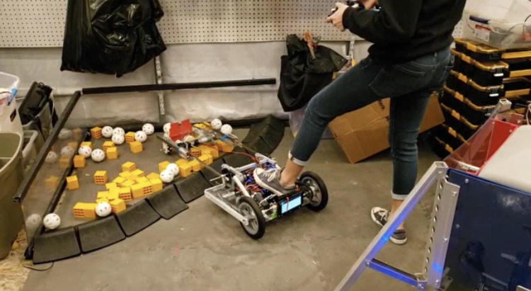
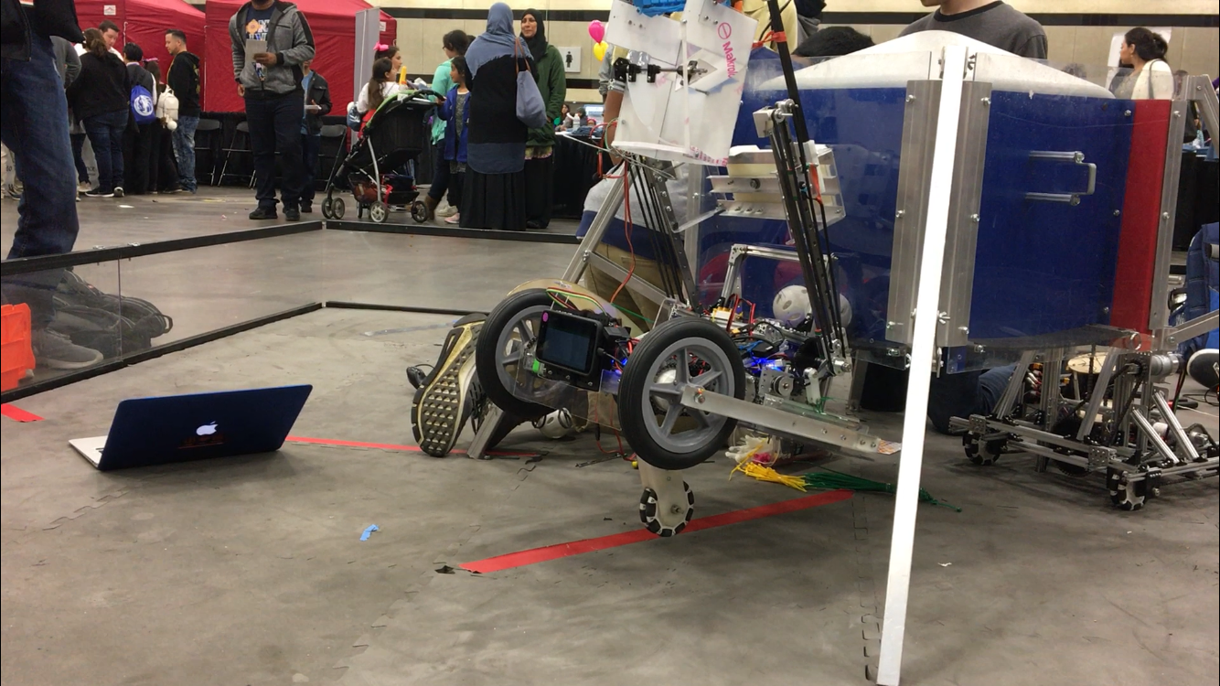
    Since then many changes have been made to Bigwheel in terms of the lift. For starters, we switched out the REV extrusion linear slide for the MGN12H linear slide. We have also added more components to intake and carry minerals. These steps have fixed the previous issue if we keep the lift at a position not exceeding ~70 degrees while moving, but having added a lot of weight to the end of the slide makes rotating around the elbow joint of Bigwheel problematic. As you can see below, Bigwheel's chassis is not heavy enough to stay grounded when deploying the arm (and so I had to step on the back end of Bigwheel like a fool).

    Another issue I encountered during driver practice was trying to deposit minerals in the lander. By "having issues" I mean I couldn't. Superman broke as soon as I tried going into the up position, and this mechanism was intended to raise Bigwheel enough so that is would reach the lander. Regardless of Superman's condition, the container for the minerals was still loose and not attached to the servo. Consequently, I could not rotate the lift past the vertical without dropping the minerals I had collected.

    Next Steps

    To run a full practice match, Superman and the container will need to be fixed, as well as the weight issue. Meanwhile, I will practice getting minerals out of the crater.

    Vision Summary

    Vision Summary By Arjun and Abhi

    Task: Reflect on our vision development

    One of our priorities this season was our autonomous, as a perfect autonomous could score us a considerable amount of points. A large portion of these points come from sampling, so that was one of our main focuses within autonomous. Throughout the season, we developed a few different approaches to sampling.

    Early on in the season, we began experimenting with using a Convolutional Neural Network to detect the location of the gold mineral. A Convolutional Neural Network, or CNN, is a machine learning algorithm that uses multiple layers which "vote" on what the output should be based on the output of previous layers. We developed a tool to label training images for use in training a CNN, publicly available at https://github.com/arjvik/MineralLabler. We then began training a CNN with the training data we labeled. However, our CNN was unable to reach a high accuracy level, despite us spending lots of time tuning it. A large part of this came to our lack of training data. We haven't given up on it, though, and we hope to improve this approach in the coming weeks.

    We then turned to other alternatives. At this time, the built-in TensorFlow Object Detection code was released in the FTC SDK. We tried out TensorFlow, but we were unable to use it reliably. Our testing revealed that the detection provided by TensorFlow was not always able to detect the location of the gold mineral. We attempted to modify some of the parameters, however, since only the trained model was provided to us by FIRST, we were unable to increase its accuracy. We are currently looking to see if we can detect the sampling order even if we only detect some of the sampling minerals. We still have code to use TensorFlow on our robot, but it is only one of a few different vision backends available for selection during runtime.

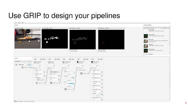
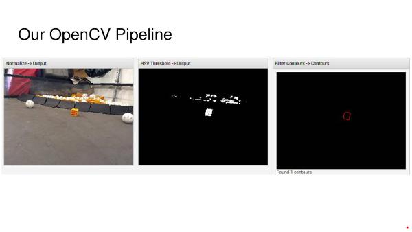
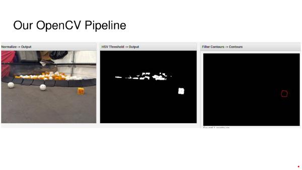
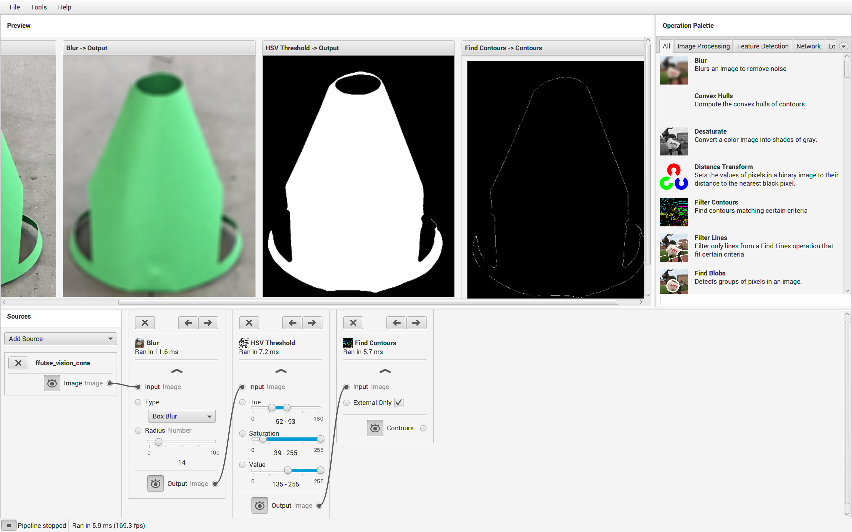
    Another alternative vision framework we tried was OpenCV. OpenCV is a collection of vision processing algorithms which can be combined to form powerful pipelines. OpenCV pipelines perform sequential transformations on their input image, until it ends up in a desired form, such as a set of contours or boundaries of all minerals detected in the image. We developed an OpenCV pipeline to find the center of the gold mineral given an image of the sampling order. To create our pipeline, we used a tool called GRIP, which allows us to visualize and tune our pipeline. However, since we have found that bad lighting conditions greatly influence the quality of detection, we hope to add LED lights to the top of our phone mount so we can get consistent lighting on the field, hopefully further increasing our performance in dark field conditions.

    Since we wanted to be able to switch easily between these vision backends, we decided to write a modular framework which allows us to swap out vision implementations with ease. As such, we are now able to choose which vision backend we would like to use during the match, with just a single button press. Because of this, we can also work in parallel on all of the vision backends.

    Another abstraction we made was the ability to switch between different viewpoints, or cameras. This allows us to decide at runtime which viewpoint we wish to use, either the front/back camera of the phone, or external webcam. Of course, while there is no good reason to change this during competition (hopefully by then the placement of the phone and webcam on the robot will be finalized), it is extremely useful during the development of the robot, because we don't have everything about our robot finalized.

      Summary of what we have done:
    • Designed a convolutional neural network to perform sampling.
    • Tested out the provided TensorFlow model for sampling.
    • Developed an OpenCV pipeline to perform sampling.
    • Created a framework to switch between different Vision Providers at runtime.
    • Created a framework to switch between different camera viewpoints at runtime.

    Next Steps

    We would like to continue improving on and testing our vision software so that we can reliably sample during our autonomous.

    Minor Code Change

    Minor Code Change By Karina

    Task: Save Bigwheel from self destruction

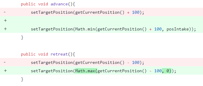
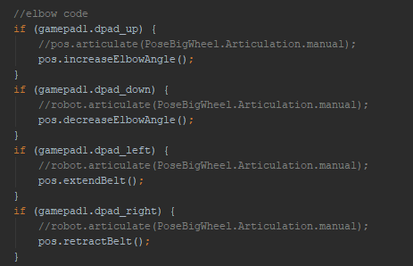
    The other day, when running through Bigwheel's controls, we came across an error in the code. The motors on the elbow did not have min and max values for its range of motion, causing the gears to grind in non-optimal conditions. Needless to say, Iron Reign has gone through a few gears already. Adding stops in the code was simple enough:

    Testing the code revealed immediate success. we went through the full range of motion and no further grinding occurred.

    Next Steps

    Going forward, we will continue to debug code through drive practice.

    Code Updates

    Code Updates By Abhi and Arjun

    Task: Detail last-minute code changes to autonomous

    It is almost time for competition and with that comes a super duper autonomous. For the past couple of weeks and today, we focused on making our depot side work consistently. Because our robot wasn't fully built, we couldn't do auto-delatching. Today, we integrated our vision pipelines into the auto and tested all the paths with vision. They seemed to work at home base but the field we have isn't built to exact specifications.

    Next Steps

    At Wylie, we will have to tune auto paths to adjust from our field's discrepancies.

    Competition Day Code

    Competition Day Code By Abhi and Arjun

    Task: Update our code

    While at the Wylie quaiifier, we had to make many changes because our robot broke the night before.

    First thing that happened was that the belt code was added. Previously, we had relied on gravity and the polycarb locks we had on the slides but we quickly realized that the slides needed to articulate in order to preserve Superman. As a result, we added the belts into our collector class and used the encoders to power them.

    Next, we added manual overrides for all functions of our robot. Simply due to lack of time, we didn't add any presets and we focused on making the robot functional enough for competition. During competition, Karina was able to latch during endgame with purely the manual overrides.

    Finally, we did auto path tuning. We ended up using an OpenCV pipeline and we were accurately able to detect the gold mineral at all times. However, our practice field wasn't setup to the exact specifications needed so we spent the majority the day at the Wylie practice field tuning depot side auto (by the end of the day it worked almost perfectly every time.

    Next Steps

    We were lucky to have qualified early in the season we could make room for mistakes such as this. However, it will be hard to sustain this, so we must implement build freezes in the future.

    Code Updates

    Code Updates By Abhi

    Task: DISD STEM EXPO

    The picture above is a representation of our work today. After making sure all the manual drive controls were working, Karina found the positions she preferred for intake, deposit, and latch. Taking these encoder values from telemetry, we created new methods for the robot to run to those positions. As a result, the robot was very functional. We could latch onto the lander in 10 seconds (a much faster endgame than we had ever done).

    Next Steps

    The code is still a little messy so we will have to do further testing before any competition.

    Autonomous Non-Blocking State Machines

    Autonomous Non-Blocking State Machines By Arjun

    Task: Design a state machine class to make autonomous easier

    In the past our autonomous routines were tedious and difficult to change. Adding one step to the beginning of an autonomous would require changing the indexes of every single step afterwards, which could take a long time depending on the size of the routine. In addition, simple typos could go undetected, and cause lots of problems. Finally, there was so much repetitive code, making our routines over 400 lines long.

    In order to remedy this, we decided to create a state machine class that takes care of the repetitive parts of our autonomous code. We created a StateMachine class, which allows us to build autonomous routines as sequences of "states", or individual steps. This new state machine system makes autonomous routines much easier to code and tune, as well as removing the possibility for small bugs. We also were able to shorten our code by converting it to the new system, reducing each routine from over 400 lines to approximately 30 lines.

    Internally, StateMachine uses instances of the functional interface State (or some of its subclasses, SingleState for states that only need to be run once, TimedState, for states that are run on a timer, or MineralState, for states that do different things depending on the sampling order). Using a functional interface lets us use lambdas, which further reduce the length of our code. When it is executed, the state machine takes the current state and runs it. If the state is finished, the current state index (stored in a class called Stage) is incremented, and a state switch action is run, which stops all motors.

    Here is an autonomous routine which has been converted to the new system:

    private StateMachine auto_depotSample = getStateMachine(autoStage)
                .addNestedStateMachine(auto_setup) //common states to all autonomous
                .addMineralState(mineralStateProvider, //turn to mineral, depending on mineral
                        () -> robot.rotateIMU(39, TURN_TIME), //turn left
                        () -> true, //don't turn if mineral is in the middle
                        () -> robot.rotateIMU(321, TURN_TIME)) //turn right
                .addMineralState(mineralStateProvider, //move to mineral
                        () -> robot.driveForward(true, .604, DRIVE_POWER), //move more on the sides
                        () -> robot.driveForward(true, .47, DRIVE_POWER), //move less in the middle
                        () -> robot.driveForward(true, .604, DRIVE_POWER))
                .addMineralState(mineralStateProvider, //turn to depot
                        () -> robot.rotateIMU(345, TURN_TIME),
                        () -> true,
                        () -> robot.rotateIMU(15, TURN_TIME))
                .addMineralState(mineralStateProvider, //move to depot
                        () -> robot.driveForward(true, .880, DRIVE_POWER),
                        () -> robot.driveForward(true, .762, DRIVE_POWER),
                        () -> robot.driveForward(true, .890, DRIVE_POWER))
                .addTimedState(4, //turn on intake for 4 seconds
                        () -> robot.collector.eject(),
                        () -> robot.collector.stopIntake())
                .build();
    

    Control Mapping

    Control Mapping By Bhanaviya, Abhi, Ben, and Karina

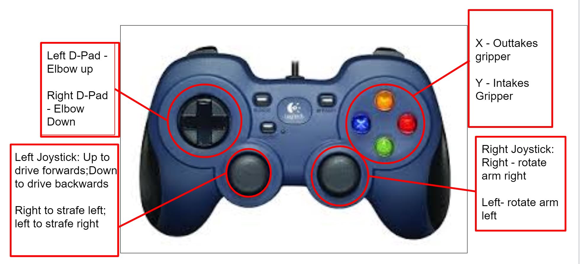
    Task: Map and test controls

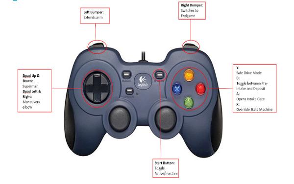
    With regionals being a week away, the robot needs to be in drive testing phase. So, we started out by mapping out controls as depicted above.

    Upon testing the controls, we realized that when the robot went into Superman-mode, it collapsed due to the lopsided structure of the base since the presets were not as accurate as they could be. The robot had trouble trying to find the right position when attempting to deposit and intake minerals.

    After we found a preset for the intake mechanism, we had to test it out to ensure that the arm extended far enough to sample. Our second task was ensuring that the robot could go into superman while still moving forward. To do this, we had to find the position which allowed the smaller wheel at the base of the robot to move forward while the robot was in motion.

    Next Steps

    We plan to revisit the robot's balancing issue in the next meet and find the accurate presets to fix the problem.

    Big Wheel Articulations

    Big Wheel Articulations By Abhi

    Task: Summary of all Big Wheel movements

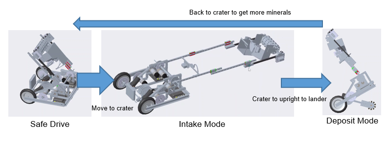
    In our motion, our robot shifts multiple major subsystems (the elbow and Superman) that make it difficult to keep the robot from tipping. Therefore, through driver practice, we determined the 5 major deployment modes that would make it easier for the driver to transition from mode to mode. Each articulation is necessary to maintain the robot's center of gravity as its mode of operation shifts.

    The position seen above is called "safe drive". During normal match play, our drivers can go to this position to navigate the field quickly and with the arm out of the way.

    When the driver control period starts, we normally navigate to the crater then enter the intake position shown above. From this position, we can safely pick up minerals from the crater.

    From the intake position, the robot goes to safe drive to fix the weight balance then goes to the deposit position shown above. The arm can still extend upwards above the lander and our automatic sorter can place the minerals appropriately.

    During the end game, we enter a latchable position where our hook can easily slide into the latch. After hooked on, our robot can slightly lift itself off the ground to hook.

    At the beginning of the match, we can completely close the arm and superman to fit in sizing cube and latch on the lander.

    As you can see, there is a lot of articulations that need to work together during the course of the match. By putting this info in a state machine, we can easily toggle between articulations. Refer to our code snippets for more details.

    Next Steps

    At this point, we have 4 cycles in 1 minute 30 seconds. By adding some upgrades to the articulations using our new distance sensors, we hope to speed this up even more.

    Cart Hack

    Cart Hack By Arjun

    Task: Tweaking ftc_app to allow us to drive robots without a Driver Station phone

    As you already know, Iron Reign has a mechanized cart called Cartbot that we bring to competitions. We used the FTC control system to build it, so we could gain experience. However, this has one issue: we can only use one pair of Robot Controller and Driver Station phones at a competition, because of WiFi interference problems.

    To avoid this pitfall, we decided to tweak the ftc_app our team uses to allow us to plug in a controller directly into the Robot Controller. This cuts out the need for a Driver Station phone, which means that we can drive around Cartbot without worrying about breaking any rules.

    Another use for this tweak could be for testing, since with this new system we don't need a Driver Station when we are testing our tele-op.

    As of now this modification lives in a separate branch of our code, since we don't know how it may affect our match code. We hope to merge this later once we confirm it doesn't cause any issues.

    Road to Worlds Document

    Road to Worlds Document By Ethan, Charlotte, Evan, Karina, Janavi, Jose, Ben, Justin, Arjun, Abhi, and Bhanaviya

    Task: Consider what we need to do in the coming months

    ROAD TO WORLDS - What we need to do


    OVERALL:

    • New social media manager (Janavi/Ben) and photographer (Ethan, Paul, and Charlotte)


    ENGINEERING JOURNAL: - Charlotte, Ethan, & all freshmen


    • Big one - freshmen get to start doing a lot more


    • Engineering section revamp
      • Decide on major subsystems to focus on
        • Make summary pages and guides for judges to find relevant articles
      • Code section
        • Finalize state diagram
          • Label diagram to refer to the following print out of different parts of the code
        • Create plan to print out classes
        • Monthly summaries
      • Meeting Logs
        • Include meeting planning sessions at the beginning of every log
          • Start doing planning sessions!
        • Create monthly summaries
      • Biweekly Doodle Polls
        • record of supposed attendance rather than word of mouth
      • Design and format revamping
        • Start doing actual descriptions for blog commits
        • More bullet points to be more technical
        • Award highlights [Ethan][Done]

    Page numbers [Ethan][Done]

        • Awards on indexPrintable [Ethan][Done]
      • Irrelevant/distracting content
        • Packing list
        • Need a miscellaneous section
          • content
      • Details and dimensions
        • Could you build robot with our journal?
        • CAD models
        • More technical language, it is readable but not technical currently
    • Outreach
      • More about the impact and personal connections
      • What went wrong
      • Make content more concise and make it convey our message better


    ENGINEERING TEAM:


    • Making a new robot - All build team (Karina & Jose over spring break)


      • Need to organize motors (used, etc)
      • Test harness for motors (summer project)
    • Re-do wiring -Janavi and Abhi
    • Elbow joint needs to be redone (is at a slight angle) - Justin/Ben
      • 3D print as a prototype
        • Cut out of aluminum
      • Needs to be higher up and pushed forward
      • More serviceable
        • Can’t plug in servos
    • Sorter -Evan, Karina, and Justin
      • Sorter redesign
    • Intake -Evan, Karina, Abhi, Jose
      • Take video of performance to gauge how issues are happening and how we can fix
      • Subteam to tackle intake issues
    • Superman -Evan and Ben
      • Widen superman wheel
    • Lift
      • Transfer police (1:1 to 3:4)
      • Larger drive pulley
        • Mount motors differently to make room
    • Chassis -Karina and a freshman
      • Protection for LED strips
      • Battery mount
      • Phone mount
      • Camera mount
      • New 20:1 motors
      • Idler sprocket to take up slack in chain (caused by small sprocket driving large one)
    • CAD Model


    CODE TEAM: -Abhi and Arjun

    • add an autorecover function to our robot for when it tips over
      • it happened twice and we couldn’t recover fast enough to climb
    • something in the update loop to maintain balance
      • we were supposed to do this for regionals but we forgot to do it and we faced the consequences
    • fix IMU corrections such that we can align to field wall instead of me eyeballing a parallel position
    • use distance sensors to do wall following and crater detection
    • auto paths need to be expanded such that we can avoid alliance partners and have enough flexibility to pick and choose what path needs to be followed
      • In both auto paths, can facilitate double sampling
    • Tuning with PID (tuning constants)
    • Autonomous optimization


    DRIVE TEAM:

    • Driving Logs
      • everytime there is driving practice, a driver will fill out a log that records overall record time, record time for that day, number of cycles for each run, and other helpful stats to track the progress of driving practice
    • actual driving practice lol
    • Multiple drive teams


    COMPETITION PREP:

    • Pit setup
      • Clean up tent and make sure we have everything to put it together
      • Activities
        • Robotics related
      • Find nuts and bolts based on the online list
    • Helping other teams
    • Posters
    • Need a handout
    • Conduct in pits - need to be focused
    • MXP or no?
    • Spring break - who is here and what can we accomplish
    • Scouting


    Code Refactor

    Code Refactor By Abhi and Arjun

    Task: Code cleanup and season analysis

    At this point in the season, we have time to clean up our code before development for code. This is important to do now so that the code remains understandable as we make many changes for worlds.

    There aren't any new features that were added during these commits. In total, there were 12 files changed, 149 additions, and 253 deletions.

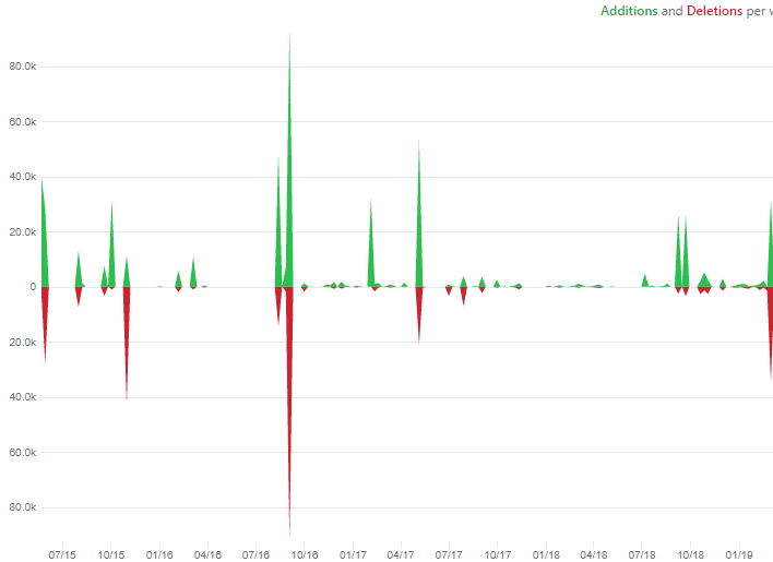
    Here is a brief graph of our commit history over the past season. As you can see, there was a spike during this code refactor.

    Here is a graph of additions and deletions over the course of the season. There was also another spike during this time as we made changes.

    Next Steps

    Hopefully this cleanup will help us on our journey to worlds.

    Localization

    Localization By Ben

    Localization

    A feature that is essential to many advanced autonomous sequences is the ability to know the robots absolute location (x position, y position, heading). For our localization, we determine the robots position relative to the fields coordinate frame. To track our position, we use encoders (to determine displacement) and a gyro (to determine heading).

    Our robots translational velocity can be determined by seeing how our encoder counts change over time. Heading velocity is simply how our angle changes in time. Thus, our actual velocity can be represented by the following equation.

    Integrating that to find our position yields

    Using this new equation, can obtain the robots updated x and y coordinates.

    Balancing Robot

    Balancing Robot By Abhi and Ben

    Initial Work on Balancing Robot

    Since our robot has two wheels and a long arm, we decided to take on an interesting problem: balancing our robot on two wheels as do modern hoverboards and Segways. Though the problem had already been solved by others, we tried our own approach.

    We first tried a PID control loop approach as we had traditionally been accustomed to that model for our autonomous and such. However, this served as a large challenge as lag in loop times didn't give us the sensitivity that was necessary. However, we tried to optimize this model.

    Next time we will continue fine tuning the gains, and use a graph plotting our current pitch versus the desired pitch to determine how we should tweak the gains to smoothly reach the setpoint. Another factor we need to account for is the varying loop times, and multiply these loop times into a pid calculations to ensure consistency. In addition, we may try to implement state space control to control this balancing instead of PID.

    Balancing Robot Updates

    Balancing Robot Updates By Abhi and Ben

    Updates on Balancing Robot

    Today we managed to get our robot to balance for 30 seconds after spending about an hour tuning the PID gains. We made significant progress, but there is a flaw in our algorithm that needs to be addressed. At the moment, we have a fixed pitch that we want the robot to balance at but due to the weight distribution of the robot, forcing it to balance at some fixed setpoint will not work well and will cause it to continually oscillate around that pitch instead of maintaining it.

    To address this issue, there are a number of solutions. As mentioned in the past post, one approach is to use state space control. Though it may present a more accurate approach, it is computationally intensive and is more difficult to implement. Another solution is to set the elbow to run to a vertical angle rather than having that value preset. For this, we would need another IMU sensor on the arm and this also adds another variable to consider in our algorithm.

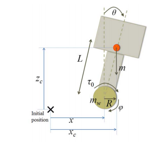
    To learn more about this problem, we looked into this paper developed by Harvard and MIT that used Lagrangian mechanics relate the variables combined with state space control. Lagrangian mechanics allows you to represent the physics of the robot in terms of energy rather than Newtonian forces. The main equation, the Lagrangian, is given as follows:

    To actually represent the lagrangian in terms of our problem, there is a set of differential equations which can be fed into the state space control equation. For the sake of this post, I will not list it here but refer to the paper given for more info.

    Next Steps:

    This problem will be on hold until we finish the necessary code for our robot but we have a lot of new information we can use to solve the problem.

    Icarus Code Support

    Icarus Code Support By Abhi

    Task: Implement dual robot code

    With the birth of Icarus came a new job for the programmers: supporting both Bigwheel and Icarus. We needed the code to work both ways because new logic could be developed on bigwheel while the builders completed Icarus.

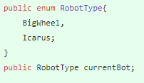
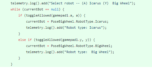
    This was done by simply creating an Enum for the robot type and feeding it into PoseBigWheel initialization. This value was fed into all the subsystems so they could be initialized properly. During init, we could now select the robot type and test with it. The change to the init loop is shown below.

    Next Steps

    After testing, it appears that our logic is functional for now. Coders can now further devlop our base without Icarus.

    Reverse Articulations

    Reverse Articulations By Abhi

    Task: Summary of Icarus Movements

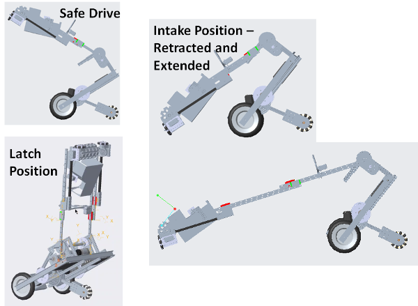
    In post E-116, I showed all the big wheel articulations. As we shifted our robot to Icarus, we decided to change to a new set of articulations as they would work better to maintain the center of gravity of our robot. Once again, we made 5 major deployment modes. Each articulation is necessary to maintain the robot's center of gravity as its mode of operation shifts.

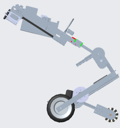
    The position seen above is called "safe drive". During normal match play, our drivers can go to this position to navigate the field quickly and with the arm out of the way. In addition, we use this articulation as we approach the lander to deposit.

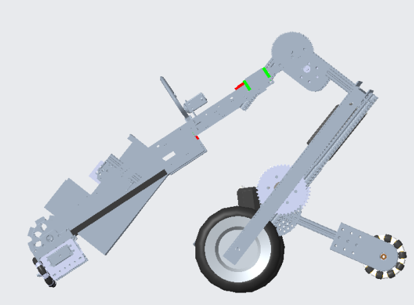
    When the driver control period starts, we normally navigate to the crater then enter the intake position shown above. From this position, we can safely pick up minerals from the crater. Note that there are two articulations shown here. These show the intake position both contracted and extended during intake.

    During the end game, we enter a latchable position where our hook can easily slide into the latch. After hooked on, our robot can slightly lift itself off the ground to hook. This is the same articulation as before.

    At the beginning of the match, we can completely close the arm and superman to fit in sizing cube and latch on the lander. This is the same articulation as before.

    These articulations were integrated into our control loop just as before. This allowed smooth integration

    Next Steps

    As the final build of Icarus is completed, we can test these articulations and their implications.

    Center of Gravity calculations

    Center of Gravity calculations By Arjun

    Task: Determine equations to find robot Center of Gravity

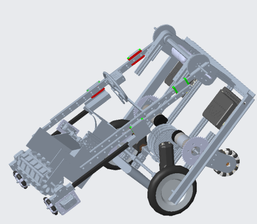
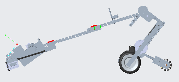
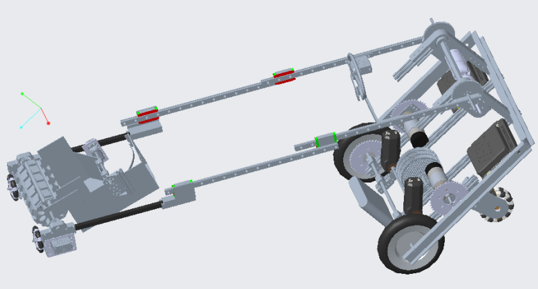
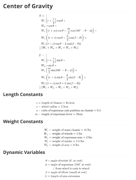
    Because our robot tends to tip over often, we decided to start working on a dynamic anti-tip algorithm. In order to do so, we needed to be able to find the center of gravity of the robot. We did this by modeling the robot as 5 separate components, finding the center of gravity of each, and then using that to find the overall center of gravity. This will allow us to better understand when our robot is tipping programmatically.

    The five components we modeled the robot as are the main chassis, the arm, the intake, superman, and the wheels. We then assumed that each of these components had an even weight distribution, and found their individual centers of gravity. Finally, we took the weighted average of the individual centers of gravity in the ratio of the weights of each of the components.

    By having equations to find the center of gravity of our robot, we can continuously find it programmatically. Because of this, we can take corrective action to prevent tipping earlier than we would be able to by just looking at the IMU angle of our robot.

    Next Steps

    We now need to implement these equations in the code for our robot, so we can actually use them.

    Code updates at UIL

    Code updates at UIL By Arjun, Abhi, and Ben O

    Task: Update code to get ready for UIL

    It's competition time again, and with that means updating our code. We have made quite a few changes to our robot in the past few weeks, and so we needed to update our code to reflect those changes.

    Unfortunately, because the robot build was completed very late, we did not have much time to code. That meant that we not only needed to stay at the UIL event center until the minute it closed to use their practice field (we were literally the last team in the FTC pits), we also needed to pull a late-nighter and stay up from 11 pm to 4 am coding.

    One of our main priorities was autonomous. We decided early on to focus on our crater-side autonomous, because in our experience, most teams who only had one autonomous chose depot-side because it was easier to code.

    Unfortunately, we were quite wrong about that. We were forced to run our untested depot-side auto multiple times throughout the course of the day, and it caused us many headaches. Because of it, we missampled, got stuck in the crater, and tipped over in some of our matches where we were forced to run depot-side. Towards the end of the competition, we tried to quickly hack together a better depot-side autonomous, but we ran out of time to do so.

    Some of the changes we made to our crater-side auto were:

    • Updating to use our new reverse articulations
    • Moving vision detection during the de-latch sequence
    • Speeding up our autonomous by replacing driving with belt extensions
    • Sampling using the belt extensions instead of driving to prevent accidental missamples
    • Using PID for all turns to improve accuracy

    We also made some enhancements to teleop. We added a system to correct the elbow angle in accordance to the belt extensions so that we don't fall over during intake when drivers adjust the belts. We also performed more tuning to our articulations to make them easier to use.

    Finally, we added support for the LEDs to the code. After attaching the Blinkin LED controller late Friday night, we included LED color changes in the code. We use them to signal to drivers what mode we are in, and to indicate when our robot is ready to go.

    Control Hub First Impressions

    Control Hub First Impressions By Arjun and Abhi

    Task: Test the REV Control Hub ahead of the REV trial

    Iron Reign was recently selected to attend a REV Control Hub trial along with select other teams in the region. We wanted to do this so that we could get a good look at the control system that FTC would likely be switching to in the near future, as well as get another chance to test our robot in tournament conditions before Worlds.

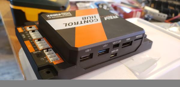
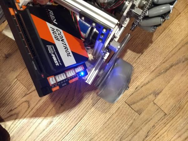
    We received our Control Hub a few days ago, and today we started testing it. We noticed that while the control hub seemed to use the same exterior as the First Global control hubs, it seems to be different on the inside. For example, in the port labeled Micro USB, there was a USB C connector. We are glad that REV listened to us teams and made this change, as switching to USB C means that there will be less wear and tear on the port. The other ports included are a Mini USB port (we don't know what it is for), an HDMI port should we ever need to view the screen of the Control Hub, and two USB ports, presumably for Webcams and other accessories. The inclusion of 2 USB ports means that a USB Hub is no longer needed. One port appears to be USB 2.0, while the other appears to be USB 3.0.

    Getting started with programming it was quite easy. We tested using Android Studio, but both OnBot Java and Blocks should be able to work fine as we were able to access the programming webpage. We just plugged the battery in to the Control Hub, and then connected it to a computer via the provided USB C cable. The Control Hub immediately showed up in ADB. (Of course, if you forget to plug in the battery like we did at first, you won't be able to program it.)

    REV provided us with a separate SDK to use to program the Control Hub. Unfortunately, we are not allowed to redistribute it. We did note however, that much of the visible internals look the same. We performed a diff between the original ftc_app's FtcRobotControllerActivity.java and the one in the new Control Hub SDK, and saw nothing notable except for mentions of permissions such as Read/Write External Storage Devices, and Access Camera. These permissions look reminiscent of standard Android permissions, and is likely accounting for the fact that you can't accept permissions on a device without a screen.

    While testing it, we didn't have time to copy over our entire codebase, so we made a quick OpMode that moved one wheel of one of our old robots. Because the provided SDK is almost identical to ftc_app, no changes were needed to the existing sample OpModes. We successfully tested our OpMode, proving that it works fine with the new system.

    Pairing the DS phone to the Control Hub was very quick with no hurdles, just requiring us to select "Control Hub" as the pairing method, and connect to the hub's Wifi network. We were told that for the purposes of this test, the WiFi password was "password". This worked, but we hope that REV changes this in the future, as this means that other malicious teams can connect to our Control Hub too.

    We also tested ADB Wireless Debugging. We connected to the Control Hub Wifi through our laptop, and then made it listen for ADB connections over the network via adb tcpip 5555. However, since the Control Hub doesn't use Wifi Direct, we were unable to connect to it via adb connect 192.168.49.1:5555. The reason for this is that the ip address 192.168.49.1 is used mainly by devices for Wifi Direct. We saw that our Control Hub used 192.168.43.1 instead (using the ip route command on Linux, or ipconfig if you are on Windows). We aren't sure if the address 192.168.43.1 is the same for all Control Hubs, or if it is different per control hub. After finding this ip address, we connected via adb connect 192.168.43.1:5555. ADB worked as expected following that command.

    Next Steps

    Overall, our testing was a success. We hope to perform further testing before we attend the REV test on Saturday. We would like to test using Webcams, OpenCV, libraries such as FtcDashboard, and more.

    We will be posting a form where you can let us know about things you would like us to test. Stay tuned for that!

    Auto Paths, Updated

    Auto Paths, Updated By Abhi

    Task: Reflect and develop auto paths

    It has been a very long time since we have reconsidered our auto paths. Between my last post and now, we have made numerous changes to both the hardware and the articulations. As a result, we should rethink the paths we used and optimize them for scoring. After testing multiple paths and observing other teams, I identified 3 auto paths we will try to perfect for championships.

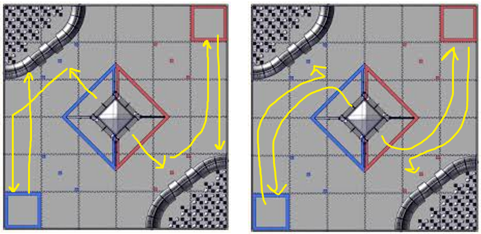
    These two paths represent crater side auto. Earlier in the season, I drew one of the paths to do double sampling. However, because of the time necessary for our delatch sequence, I determined we simply don't have the time necessary to double sample. The left path above is a safe auto path that we had tested many times and used at UIL. However, it doesn't allow us to score the sampled mineral into the lander which would give us 5 extra points during auto. That's why we created a theoretical path seen on the right side that would deposit the team marker before sampling. This allows us to score the sampling mineral rather than just pushing it.

    This is the depot path I was thinking about. Though it looks very similar to the past auto path, there are some notable differences. After the robot delatches from the lander, the lift will simply extend into the depot rather than driving into it. This allows us to extend back and pick up the sampling mineral and score it. Then the robot can turn to the crater and park.

    Next Steps

    One of the crater paths is already coded. Our first priority is to get the depot auto functional for worlds. If we have time still remaining, we can try to do the second crater path.

    Fixing Mini-Mech

    Fixing Mini-Mech By Cooper

    Task: Fix Mini-Mech in time for the Skystone reveal

    In two weeks, Iron Reign is planning on building a robot in 2 days, based on the 2019-2020 Skystone Reveal Video. We've never really built a robot in that short span of a time, so we realized that preparing a suitable chassis ahead of time will make the challenge a lot easier as it gives us time to focus on specific subsystems and code. As such, I worked on fixing up Mini Mech, as it is a possible candidate for our robot in a weekend, due to its small size and maneuverability. Mini-Mech was our 4-wheeled, mecanum-drive,summer chassis project from the Rover Ruckus season, and it has consistently served as a solid prototype to test the early stages of our build and code. I started by testing the drive motors, and then tightening them down, since were really loose.

    Then, I worked on adding a control hub to the chassis. Since Iron Reign was one of the teams who took part in REV's beta test for the control hubs last season, and because we are one of the pilot teams for the REV Control Hub in the North-Texas Region, using a control hub on our first robot of the season will help set us up for our first qualifier, during which we hope to use a control hub.

    Next Steps

    With MiniMech fixed, we now have at least one chassis design to build our Robot in 2 Days off of.

    Ri2D Code

    Ri2D Code By Jose

    Task: Code a Basic TeleOp Code for the Ri2D bot using pre-existing classes and methods

    As the Ri2D bot nears completion, the need for TeleOp code becomes apparent to actually make it move. Since this robot is based of from MiniMech, a previous chassis design for Rover Rockus, the code was simply inserted into its existing class. To allow its subsystems to move and hold their position when they are not, methods for it to pose were used from the code for Icarus, our Rover Rockus robot. Most of the `PoseBigWheel` class wont be used for this robot, but that's fine since that is as simple as not using the methods not needed, done. The constructor for the `PoseBigWheel` class needed to be modified since there are different motors and servos used, this was easy as we just needed to remove anything we didn't need. Again, most stuff here won't be used, but as long as we don't delete any PIVs we should be fine.

    Once the code for robot posing is made to match the Ri2D bot, we need to implement it. To do this an instance of this class was instantiated in the `MiniMech` class. With that, we can now use methods of the `Crane` class(the one with robot posing) in the `MiniMech` class.

    Now it's time to use these methods from the `Crane` class. Since the elbow and slides are the same from Icarus we can apply these methods directly. These were simple if statements to detects a button press and set the appropriate motor moving using the posing code from the `Crane` class. Instead of using basic `setMotor` commands to get the motors going, pre-coded methods were used, we can now keep the motors in the position where they are placed in the same amount of complexity and with no previous knowledge of how to code robot poseing.

    Finally, we have to code the servos. Since the `Crane` class comes with code for two servos we can advantage of it since the Ri2D bot has only two servos. Although the code for this is a lot simpler since robot posing isn't required here, it is still nice to have values for the open and closed positions stored in a PIV in the `Crane` class if we ever have to change them later. A simple toggle feature was used so one button sets the servo to an open position when closed and vice versa.

    Next Steps

    We could on some robot articulations later on, but a basic TeleOp program is good for now.

    FrankenDroid - TPM Calibration

    FrankenDroid - TPM Calibration By Jose, Cooper, and Bhanaviya

    Task: Calibrate FrankenDriod's Ticks Per Meter in preparation of programming autonomous

    Today we worked on the calibration of FrankenDriod's TPM. This is used to accurately and precisely move during autonomous by having a conversion factor between a given distance and the unit ticks, which is used in the code. This was done by commanding FrankenDroid to move forward 2000 ticks. Of course this wasn't a meter, but the distance it did travel(in centimeters) was divided by 100 and multiplied by 2000(estimate used above) to get the approximate TPM. After a few times of getting the number of ticks perfect, we got it exact to the centimeter. This was also done for strafing and with that we now have an exact TPM that can be used when programming autonomous.

    Next Steps

    Now for the fun part, actually programming auto paths. These will be planned out and coded at a later date.

    Beginning Auto Stone

    Beginning Auto Stone By Cooper and Karina

    Task: Design an intake for the stones based on wheels

    Initial Design: Rolling Intake

    We've been trying to get our start on autonomous today. We are still using FrankenDroid (our R12D mecanum drive test bot) because our competition bot is taking longer than we wanted. We just started coding, so we are just trying to learn how to use the statemachine class that Arjun wrote last year. We wanted to make a skeleton of a navigation routine that would pick up and deposit two skystones, although we ran into 3 different notable issues.

    Problem #1 - tuning Crane presets

    We needed to create some presets for repeatable positions for our crane subystem. Since we output all of that to telemetry constantly, it was easy to position the crane manually and see what the encoder positions were. We were mostly focusing on the elbow joints position, since the extension won't come into play until we are stacking taller towers. The positions we need for auto are:

    • BridgeTransit - the angle the arm needs to be to fit under the low skybridge
    • StoneClear - the angle that positions the gripper to safely just pass over an upright stone
    • StoneGrab - the angle that places the intake roller on the skystone to begin the grab

    Problem #2 - learning the statemachine builder

    I've never used lambda expressions before, so that was a bit of a learning curve. But once I got the syntax down, it was pretty easy to get the series of needed moves into the statemachine builder. The sequence comes from our auto planning post. The code has embedded comments to explain what we are trying to do:


    Problem #3 - REV IMU flipped?

    This was the hard one. We lost the last 1.5 hours of practice trying to figure this out, so we didn't get around to actually picking up any stones. We figured that our framework code couldn't have this wrong because it's based on last year's code and the team has been using imu-based navigation since before Karina started. So we thought it must be right and we just didn't know how to use it.

    The problem started with our turn navigation. We have a method called rotateIMU for in-place turns which just takes a target angle and a time limit. But the robot was turning the wrong way. We'd put in a 90 degree target value expecting it to rotate clockwise looking down at it, but it would turn counter clockwise and then it would oscillate wildly. Which at least looked like it found a target value. It just looked like very badly tuned PID overshoot and since we hadn't done PID tuning for this robot yet, we decided to start with that. That was a mistake. We ended up damping the P constant down so much until it had the tiniest effect and the oscillation never went away.

    We have another method built into our demo code called maintainHeading. Just what it sounds like, this lets us put the robot on a rotating lazy susan and it will use the imu to maintain it's current heading by rotating counter to the turntable. When we played with this it became clear the robot was anti-correcting. So we looked more closely at our imu outputs and yes, they were "backwards." Turning to the left increased the imu yaw when we expected turning to the right would do that.

    We have offset routines that help us with relative turns so we suspected the problem was in there. however, we traced it all the way back to the raw outputs from the imuAngles and found nothing. The REV Control Hub is acting like the imu module is installed upside down. We also have an Expansion Hub on the robot and that behaves the same way. This actually triggered a big debate about navigation standards between our mentors and they might write about that separately. So in the end, we went with the interpretation that the imu is flipped. Therefore, the correction was clear-- either to change our bias for clockwise therefore increasing in our relative turns, or to flip the imu output. We decided to flip the imu output and the fix was as simple as inserting the "360-" to this line of code:

    poseHeading = wrapAngle(360-imuAngles.firstAngle, offsetHeading);

    So the oscillation turned out to be at 180 degrees to the target angle. That's because the robot was anti-correcting but still able to know it wasn't near the target angle. At 180 it flips which direction it thinks it should turn for the shortest path to zero error, but the error was at its maximum, so the oscillation was violent. Once we got the heading flipped correctly, everything started working and the PID control is much better with the original constants. Now we could start making progress again.

    Though, the irony here is that we might end up mounting one of our REV hubs upside down on our competition robot. In which case we'll have to flip that imu back.

    Next Steps

    1)Articulating the Crane- We want to turn our Crane presets into proper articulations. Last year we built a complicated articulation engine that controlled that robot's many degrees of freedom. We have much simpler designs this year and don't really need a complicated articulation engine. But it has some nice benefits like set and forget target positions so the robot can be doing multiple things simultaneously from inside a step-by-step state machine. Plus since it is so much simpler this year and we have examples, the engine should be easier to code.

    2)Optimization- Our first pass at auto takes 28 seconds and that's with only 1.5 skystone runs and not even picking the first skystone up or placing it. And no foundation move or end run to the bridge. And no vision. We have a long way to go. But we are also doing this serially right now and we can recover some time when we get our crane operating in parallel with navigation. We're also running a .8 speed so can gain a bit there.

    3)Vision- We've played with both the tensor flow and vuforia samples and they work fairly well. Since we get great positioning feedback from vuforia we'll probably start with that for auto skystone retrieval.

    4)Behaviors- we want to make picking up stones an automatic low level behavior that works in auto and teleop. The robot should be able to automatically detect when it is over a stone and try to pick it up. We may want more than just vision to help with this. Possibly distance sensors as well.

    5)Wall detection- It probably makes sense to use distance sensors to detect distance to the wall and to stones. Our dead reckoning will need to be corrected as we get it up to maximum speed.

    Auto Path 1

    Auto Path 1 By Karina and Jose

    Task: Lay out our robot's path for autonomous

    To kick off our autonomous programming, Iron Reign created our first version autonomous path plan. We begin, like all robots, in the the loading stone, its back to the field wall and with our intake arm upwards. We approach the line-up of stones and deploy the arm to its intake state over the last stone. At the same time, we have the wheels of the gripper rotating for a few seconds. The, we back up directly. Using IMU, our robot rotates 90 degrees, and then crosses underneath the skybridge to the building zone. About 1 foot past the end of the foundation closest to the bridges, we rotate again to the right and then deposit our stone. Afterwards, we retract the intake arm, back up, and then park underneath the skybridge.

    Next steps: Improving autonomous by testing

    The autonomous we have now is very simple, but this is only our first version. There are multiple steps that can be taken to increase the amount of points we score during autonomous.

    In testing, I've noticed that (depending on how successfully we initialize our robot) the stone we pick up during autonomous sometimes drags on the ground. This creates a resistive force that is not healthy of our intake arm, which is mounted on the robot by a singular axle. To fix this, we can add code to slightly raise the arm before we began moving.

    Eventually, when multiple teams on an alliance have an autonomous program, our own path will need to account for possible collisions. It will be strategic to have multiple autonomous paths, where one retrieves stones and places them on the foundation, while the other robot positions itself to push/drag the foundation to the depot.

    Also, our autonomous path is geared toward being precise, but going forward into the season, we will need to intake and place more stones if we want to be competitive. As well, we will need to use robot vision to identify the skystone, and transport that stone to the foundation, since this earns more points.

    Coding 10/19/19 (Putting meat on the skeleton)

    Coding 10/19/19 (Putting meat on the skeleton) By Cooper

    Task: work on actually filling out the auto

    As seen in the last post, the skeleton of the auto was done. Tonight My goal was to fill it out-- make it do the things it needs to at the points based on the skeleton. This Would have been a bit more automated had we put a distance sensor on the robot, as I could just tell it to do certain actions based on how far it was from something. Without that, all I could do was hard code the distances. This took most of the time, but was efficient since I did it in stages.

    Stage 1 - The blocks

    My first task was to pick up the first block in the quarry line. I started by going forward and estimating the amount I needed to go, then went into the arm. I needed to make sure that when I went forward, I would go over the block just enough that I didn't move in when moving, but low enough to be able to be picked up with relative ease. So I ran a teleop version of this and got the value for the arm above the block, grabbing the block and just low enough to clear the bridge, a value I'd need later. Then I did trial and error on guessing the distance to the block until the grabber was in position just over the block. Then I ran into a little issue. I wanted to run the intake servos while I put the arm down, but in the StateMachine class, we can only have one action happening at a time per StateMachine object. Therefore, I just set it to run the servos after the arm was put down.

    However there was a separate issue concerning that as well. In the intake method, we assign a value to our servo PIVs to control the speed at which they run. This is how you are supposed to do that, the only problem is that that by itself is not compatible with our StateMachine. As we use Lambda functions, the code runs through the lines of .addState() repeatedly until the method call in the method call in that .addState() call returns true. For starters, we had to change the output method to return a boolean value. But isn't it, as if it was left as that, the lambda funtion would always get back a false from that .addState(), and be stuck like that until we stop it. So, I looked back on the old code from last year, and with the help of Mr.V, we found a .addTimedState() method. This takes in a method like a normal .addState() method, but a time to complete can be assigned. With the intake method always returning false, it means that the servos would run until the end of the time set and then it would end that action and move on to the next.

    Stage 2 - The deposit

    So, after the bock was picked up, the robot was told to turn to the other end of the field, where another set of estimations were used to move forward. This is where the value of just clearing the bridge came to play. To get under the bridge, we have to hold the block and arm in a certain position. After the bridge is cleared, the arm is set to move back up so when we turn to face the build plate, we could deposit. Now this was interesting. As hard as I tried I could not get the deposit to work reliably, but some of the accidental effects gave me ideas for how to get the most efficient way of placing the block. On one of the runs, the block was set down and it didn't quite sit where it needed to, as to say it was tilted back away from the robot. This led to the arm knocking it back into the correct place. I think this is a great way to have a more catch-all way make sure that the first block is correctly placed. I would have expanded on the idea, but I had to leave soon after.

    Next Steps

    I need to test more efficient paths for this auto, but other than that, I just need to finish this version of the auto for the scrimmage.

    Control Mapping

    Control Mapping By Bhanaviya and Cooper

    Task: Map and test controls

    With the Hedrick Middle School scrimmage being a day away, the robot needs to be in drive testing phase. So, we started out by mapping out controls as depicted above.

    Upon testing the controls, we realized that when the robot attempted to move, it was unable to do so without strafing. To fix this issue, we decided to utilize a "dead-zone" of the left joystick. The dead-zone is a range of values in our code that is basically ineffective. Although this meant that that the zone did not have a purpose, we realized that its uselessness could be rendered to stop the robot from strafing. Although we do plan to implement strafe later on in our actual competition robot (TomBot), for the duration of the scrimmage, the deadzone in Frankendroid's (our scrimmage robot) controls will hold the set of values for strafe so that the robot cannot strafe at any point in time during the scrimmage. This will give our drivers more control over the robot during matches.

    Next Steps

    We plan to drive-test at the scrimmage tomorrow to ensure that the robot can move accurately without strafing. Once we begin code on Iron Roomba, we plan to orient strafe in such a way that it does not interfere with the rest of the robot's controls. At any rate, the dead-zone has given us a possible solution to work with if the strafe issue occurs on our competition bot.Since this is the control map for our scrimmage robot, we anticipate that the controls will change once Iron Roomba is further along in the engineering process. A new post featuring Roomba's controls will be created then.

    Driving at the Hedrick Scrimmage

    Driving at the Hedrick Scrimmage By Karina and Jose

    Task: Figure out what went wrong at the scrimmage

    We didn't do too well in teleop driving at the Hedrick Scrimmage, with our max stone deposit being 2 stones. There are several things to blame.

    In usual Iron Reign fashion, we didn't start practicing driving until a day or two before. Since we were not familiar with the controls, we could no perform a maximum capacity.

    There were also more technical issues with our robot. For one, the arm was mounted wihh little reinforcement. Small amounts of torque provided when dragging a stone across the floor gradually made it so that the line of the arm was not parallel to the frame of the robot, but slightly at an angle. And so, picking up the stones manually was not as straight forward a task as it should have been.

    This flaw could easily have been corrected for if Frankendroid could strafe. Frankendroid struggled with this. When extended, the weight of the arm lifted the back wheel opposite the corner on which the arm was mounted on off the ground. Thus, strafing to align with a stone when the arm was extended was a lengthy and tedious task.

    Next steps:

    Frankendroid has served its purpose well: it moved at the scrimmage and gave the team a better feel for the competition environment. But it's time to let go. Moving forward, Iron Reign will focus its efforts on building our circular TomBot Ironically, we will likely have to deconstruct Frankendroid to harvest parts.

    Coding Before Scrimmage

    Coding Before Scrimmage By Cooper, Karina, Bhanaviya, and Trey

    Task: Finish the temporary auto and work with drivers for teleop

    Tonight, the night before the scrimmage, We worked on making the depositing of the stone and parking of the robot more reliable. Or as reliable as possible, as we are planning to use FrankenDroid, which is somewhat in need of repair, which I also did with the help of Trey, Bhanaviya and Karina. This had a few changes come with it, as while we solved the problems of when we started the auto, there were still many that cropped up.

    Problem #1 - dragging the base

    In the auto, we need to drag the build area into the taped off section in the corner. This poses a problem, as dragging it can lead to major inaccuracies in estimated positioning. This, however can be solved somewhat easily once we have a distance sensor, which we could use in junction with PID based turning. Though in theory I could have done it with just the PID turning. While I would have loved to test that, there was another problem--

    Problem #2 - problem with hook

    There was a problem with our hook. I tried every time I ran auto to get the hook to work. I changed the return value, I changed the physical positioning of where it started, yet nothing worked. This was interesting, as it does work in the teleop. In any case, it prevented us to actually dragging the base in this version of auto. Looking back on it, there was a possibility that I needed to set it as a timed state, like the gripper, since we were using a servo to control it. While its unlikely, it's possible.

    Problem #3 - PID Tuning?

    This was the major issue of tonight, which we haven't found the root of just quite yet. During the auto, at the third turn, where the robot turns to heat to the foundation, there is a ~25% chance that the PID does not check where it turns and it just continues wherever it turns to. This usually leads to it overshooting and then ramming in to the wall. There is a temporary fix, however. For now, it seems that if only happens after we upload the code to the robot, or if we run auto fresh off of it being off. That is to say, if we run the auto at least for a second and then reset and re-init, then it will be good. This is a good thing however, as any chance we get to fix the underlying code's problems, that means we won't have to make a work around after in the season.

    Problem #4 - putting the block on the build platform

    This was the major fixable problem in the code. During auto, we need to take a block from the quarry and put it on the foundation. The problem is when we actually go to deposit it. When we go to put it down, we need to be very accurate, which with FrankenDroid is not easy. With no distance sensors, the best we can do is to tune the exact movements. While this isn't the greatest solution, this will do for now. In the future, we will have a distance sensor so that we can know where we are exactly in relation to the base.

    Next Steps

    We need to implement the distance sensors and other sensors on the robot. Obviously we aren't going to be using FrankenDroid for too much longer. TomBot may bring new innovations like a telemetry wheel which will make auto more accurate.

    Hedrick Scrimmage - Code

    Hedrick Scrimmage - Code By Jose and Cooper

    Task: Discuss what went and what needs improvement in our code

    Taking part in the annual Hedrick Scrimmage, we got to test our Robot In 24 Hours, FrankenDroid. Specifically, since both coders on the team are new to the sub-team, we wanted to see the code capabilities we could offer. For this event we had two autonomous paths: the first one simply walks underneath the skybridge for some easy 5 points, the other grabs a stone(we had no vision on FrankenDroid so no way to detect a skystone), moves to the building zone to drop said stone and parks under the skybridge. For being coded in a just a few days, these auto paths were both high in pointage and accuracy/precision. As well as auto, we wanted to test driver enhancements. These were coded at the event but proved to be useful. They include: a button press to move the arm to either fully retracted, perpendicular to the ground for strafing, and disableing strafing whilst in stacking or intake mode. These also proved to be effective on the playing field, making the drivers' life easier.

    Next Steps

    We need to incorporate vision into our autonomous, most likely Vuforia, to be able to detect skystones as well as speeding up the auto paths to be able to complete a 2 skystone auto.

    Transition from Expansion Hub to Control Hub

    Transition from Expansion Hub to Control Hub By Jose and Cooper

    Task: Discuss the transition from using the Expansion Hub to using the Control Hub

    Over the past month we have used the control hub our robot in 24 hours, FrankenDriod. This was a great way to test its viability before implementing in onto our competition robot. We have already used the control hub at the REV test event where we were given a sample control hub to replace the existing expansion hub in our Rover Rockus bot. This proved the control hub to be much better than the expansion hub since there was no worry of a phone disconnect mid-match. This was no different on FrankenDriod, as we had less ping, didn't have to worry about a phone mount, and most important of all, we could push code to it via wifi. This is a useful feature since modifications to the bot's code can be done on the spot with no need for a wired connection. The only downside we see as of now is that an external webcam must be used for vision, this of course, is because we no longer have a phone to this. This is fine since we are used to using a camera for vision anyways so there is no difference there.

    Next Steps

    Considering that our team is one of the NTX teams who have received permission to beta-test a control hub at qualifiers, we will now use it on our current competition bot, Iron Roomba, especially since we have proven the control hub to be fully viable on a competition bot, having used FrankenDroid at the Hedrick Scrimmage.

    Coding TomBot

    Coding TomBot By Cooper and Jose

    Task: Use existing code from the code base to program TomBot

    To code TomBot, we decided to use the codebase from Frankendroid, as its the one we were most comfortable with. This will change after the qualifier, as we recognize that the robot is more like last year's robot, Icarus. This will, in the long run, help us as we will be able to minimize the amount of refactoring we have to do. But in the meantime, we made 4 major changes in the code for Tombot.

    Change #1 - Mecanum Drive to Differential

    The first was the change from a mecanum drive to a differential, arcade style control. This was done by commenting out the lines for strafing, and changing the method call to a dormant method, which was a remnant from some testing done with a linear op mode for an early version of FrankenDroid. We got rid of the power assignment for the front motors, and just used the back two motors to represent our 2 drive motors. This gave us some trouble, which I’ll cover later. After that trouble, the method was still broken, as the left stick y was controlling the left motor, and the right stick x was controlling the right motor. This was due to the incorrect power assignments in the code. With that fix done, it drove as it should after the switching of an encoder cable.

    Change #2 - Rolling Gripper to 3-finger gripper

    The next 'big' change was the change from the rolling gripper on frankenDroid to the 3- finger design on TomBot. I use the word big lightly, as it wasn't more than commenting out the lines for one of the servos. However, this will have a major impact, which can be seen in the details in our grippers post. This is also note worthy in terms of auto, as it will have adverse effects on auto. This is due to the current instability and overall unpredictability of it. So, in auto, we will have to compensate for it.

    Change #3 - Turret

    One of the biggest changes to the code base we made was with the Turntable class that I wrote. This was also, therefore, the hardest part. Due to the fact I'm still relatively new to this, I got a lot of my examples from the Crane class that Ahbi wrote last year. I started first by tackling making a basic skeleton, including methods like rotateTo() and rotateRight(). Then I started filling them in. For some reason, the first go around at this, I decided to through out all the things they taught me in school and use rotateRight() and rotateLeft() as my lowest level method, instead of rotateTo(). Another thing I failed to realize is that I didn't fully get the Crane class, and made a redundant positionInternal variable for the encoder values that is assigned at the rotate method calls and then another variable called currentPosition was assigned to that, and then the encoder value for the motor was set to that. This sounds stupid, because it was. This cost me a good day of working and was a great lesson in taking my time understanding something before I go off and do it

    Once I had realized my misunderstandings of the Crane class, I was able to move on. I cut out all the unnecessary positionInternal code, using the other variable (currentRotation) to be changed in the rotate mehtods. Speaking of, I also got some sense into me and changed the rotate methods to use setRotation() as its lower-level method, making the code more professional in nature. This, still, was not our only problem. Next was encountered a bizzare glitch-like attribute to using the rotate methods. There was a sporadic, sudden movement whenever we pressed the button assigned for turning the table (the a button as it was just a test). After many looks at all the possible variables of failure, we whittled it down to be the fact that we assigned it to the controllers A button. What we observed was the turntable working, just not how we thought we were telling it to. In the button map, there was a method called toggleAllowed() infront of all the boolean-value button. This, unbeknownst to me was actually a toggle method written by Tycho many years ago. This toggle made it so the action assigned to the button only happened once, which is useful for things like latches and poses, as the driver could overshoot it if left to un-press the button in the correct amount of time. This, however, in our case led to the turnLeft() method (the one assigned at the time) only happen once, which was that sudden, sporadic movement after the a button.

    Once we changed it to a trigger, it worked-- almost. there was still some bug in the code that made it do some pretty funky stuff, which is hard to describe. After we whittled it down to just a small error of changing a negative to a positive, it worked perfectly.

    Change #4 - XML file

    During the Woodrow Scrimmage, I spent most of my time dealing with null pointer exception errors and incorrect XML assignments. This was, again, due to a lack of knowledge of the code base. I tried to comment out certain motors, which led to the null pointers, and tried to get rid of those null pointers in the XML file. After awhile of this loop, I realized my mistake in that the null pointers were due to a method call on an uninstantiated object. When I put all the assignments back in the Init, I was finally able to get it running

    Next Steps

    My next steps are to tune the PID values for auto, so I can use the skeleton from FrankenDroid. Then I need to take some of the sounds from the driver phone, like the critical error one, as it can severely affect workflow and my sanity. Finally, I need to change the turret to make it so that it uses the IMU heading instead of entirely the encoder value from the turntable.

    Last Minute Code Changes

    Last Minute Code Changes By Cooper

    Task: Debug some last-minute code to be ready for our first qualifier of the season

    This article may seem a bit rushed, but that's because it is - for good reason. Tonight is the night before the qualifier and it’s roughly 2 in the morning. Tonight we got a lot done, but a lot didn’t get done. We can explain.

    We finally have a robot in a build state that we could use to test the code for the turntable properly. The only tragedy - it wasn’t refined, per say. But it’s good enough for tonight. There are some random discrepancies between the controller and the actual turning portions of the turntable, but they seem to be largely minute.

    Next, we had issues just a bit earlier tonight with the elbow. First off, the elbow was backwards. The elbow would count the ticks backwards, such that down was a positive tick direction. Looking through all the code, we saw that the motors’ encoder value was flipped through a direct call to the DCMotor class. So we turned that one off and tried it but that didn’t work, so we then found another and put back the first in a different position in the code, thinking they’d cancel out. But, eventually, the solution was as simple as taking out the encoder values, which allowed the elbow to count the ticks forward. We plan to fine-tune our solution after the qualifier, but for now, it will allow the elbow to work.

    Next steps

    Get some sleep and then refine and complete the code tomorrow morning at the qualifier, and hopefully write some auto

    Post-Qualifier Code Debugging

    Post-Qualifier Code Debugging By Cooper

    Task: Debug code after the Allen Qualifier

    After the qualifier, along with articulation plans, we had a long list of bugs in the code that needed to be sorted out. Most of them were a direct effect of not being able to test the code until the night before the qualifier. In hindsight, there were some issues which needed to be debugged in the turntable and turret.

    The first one that we tackled was the turntable wind up and delay. This was one of the bigger problems, as it led to the instabilities seen at the qualifier. These included random jerking to one side, inconsistent speed, and most importantly the delay. As described by Justin, it was a 2-3 second time period in which the turntable did nothing and then started moving. This was especially important to fix for stacking, as quite obviously precision and careful movements are key to this game.

    So we started at the source of what we thought was the discrepancy— the rotateTurret() method. This was under scrutiny, as it was the lowest level call, or in other terms the only code that assigns new tick targets to the motor. In the rotate methods that are called by other classes, we assigned a new value to a different value called currentRotation. Once one of the rotate (right or left) methods were called, then the new value would be assigned to currentRotation. Then where the update() method for this turret class was called in the loop, it would call rotateTurret(), which would them assign currentRotationInternal to currentRotation, and then subsequently call the setTargetPositon() giving currentRotationInternal as it’s new tick value target position.

    We also started going through the demo mode that was written last year. We have this idea for a great cool demo mode that will be documented once it’s in progress. However, to get there we need a working IMU. We technically had an IMU that worked at the competition, though it was never properly used or calibrated. So, we decided to look into getting the IMUs running. We started by looking at the current demo code and seeing what it could do. Most of it was outdated. But, we did find what we were looking for- the maintainHeading() method, in which we called another method, driveIMU. We then wrote a new maintainHeadingTurret() which works pretty well. Granted, we need to adjust the kP and kI values for the PID, but that is quite easy.

    Next Steps

    Continue tuning PID values in both the turn-table and turret.

    Future TomBot Articulations

    Future TomBot Articulations By Cooper

    Task: Plan out potential robot articulations to improve game strategy

    Getting back from the tournament, we were able to immediately start to think about what was the big problems and possible improvements to the articulations of the robot. Overall, we ended up coming up with several ideas, both for fixing things and for efficiency.

    1- Turntable Articulations

    In the competition, we realized the extreme convenience that having some articulations for the turret. Not to say that we hadn't tried to make them before the competition, we were having some issues writing them. plus, even if we didn't have those convene, it would have been improbable that we would have gotten them tuned for the competition. Anyways, even though we agreed on needing to have these presets, we could not agree on what they should be. One argument was that we should have them field-centric, meaning that it would stay in one position from the POV of the audience. This was cited to have a good number of use cases, such as repetitive positions, like the left/right and forward of the field. However, another idea arose to have them be robot-centric. This would allow for faster relative turns.

    So, what we've decided to do is write the code for both. The field-centric will be turns and subsequent static positions will implement the IMU on the control hub mounted to the turret. The robot-centric version will be based on the tick values of the encoders on the turret's motor. Then, we will have the drivers choose which one they prefer. This we believe is effective, as it will allow for a more consistent use of the turntable for the driver.

    2- Move to Tower Height Articulations

    this is one of the more useful Ideas, which would be to extend the arm to the current height of the tower. How would we do it? Well, we have come up with a 2 step plan to do this, in different levels of difficulty. The first one is based on trig. We used the second controller to increment and decrement the level of the current tower. That value is then used in the extendToTowerHeight() method, which was written as the following:

    public void extendToTowerHeight(){ hypotenuse = (int)(Math.sqrt(.25 * Math.pow((currentTowerHeight* blockHeightMeter),2)));//in meters setElbowTargetPos((int)(ticksPerDegree*Math.acos(.5/ hypotenuse)),1); setExtendABobTargetPos((int)(hypotenuse *(107.0/2960.0))); }

    As you can see, we used the current tower height times the height of a block to get the opposite side of the triangle relative to our theta, in this case the arm angle. The .25 is an understood floor distance between the robot and the tower. This means that the arm will always extend to the same floor distance every time. We think this to be the most effective, as it means not only that the driver will have a constant to base the timing of the extension, but we minimize the amount we have to extend our arm. If we assumed the length of the hypotenuse, there would be overextension for lower levels, which would have to be accounted for.

    The next phase of the design will use a camera to continue to extend the arm until it doesn't see any blocks. not only will this allow for a faster ascension and more general use cases, It will eliminate the need for a second controller (or at least for this part.

    3-Auto-grab Articulation

    Finally, the last one that we came up with is the idea to auto-grab blocks. To do this we would use vison to detect the angle and distance that block is away from the robots back arm and extend to it. Then rotate the gripper, snatch it and reel it back.

    Next Steps

    Use a culmination of drive testing and experimentation to refine the robots movements and ultimately automate the robot’s actions.

    Turret IMU Code

    Turret IMU Code By Jose and Abhi

    Task: Code some driver enhancements for the turret

    With the return of the king(Abhi - an alumni of our team) we were able to make some code changes, mainly dealing with the turret and its IMU since that is our current weak point. At first we experimented with field-centric controls but then realized that for ease of driving the robot, turret-centric control are necessary. After a few lines of code using the turret's IMU, we were able to make the turret maintain its heading, as the chassis turn, so does the turret to maintain its position. This is useful because it will allow the driver to turn the chassis without having to turn the turret as well.

    Next Steps

    We must continue tuning the PID of the turret to allow for more stable and accurate articulations.

    Code Developments 12/28

    Code Developments 12/28 By Cooper

    Task: Gripper swivel, extendToTowerHeight, and retractFromTowerHeight. Oh My!

    Today was a long day, clocking in 10 hrs continuously. In those ten hours, I was able to make tremendous progress. Overall, we have 4 main areas of work done.

    The first one gets it’s own blog post, which is the extendToTowerHeight, which encompasses fixing the 2nd controller, calculating the TPM of the arm, and calculating the TPD for the elbow.

    The second focus of the day was mounting and programming the swivel of the gripper. Aaron designed a swivel mount for the gripper the night after the qualifier, which was mounted on the robot. It was taken off by Aaron to finish the design and then today I put it back on, and then wired it. Once we tested to make sure the servo actually worked, we added a method in the Crane class that swivels the gripper continuously. But, since the servo is still a static one, I was also able to implement a toggle that toggles between 90, 0, and -90. With a couple of tests we were able to determine the correct speed at which to rotate and the code ended up looking like this:

    public void swivelGripper(boolean right){ if(right == true) gripperSwivel.setPosition(gripperSwivel.getPosition()-.02); else gripperSwivel.setPosition(gripperSwivel.getPosition()+.02); }

    The third development was the retractFromTowerHeight() method that was written. This is complementary to extendToTowerHeight, but is significantly less complex. The goal of this method was to make retracting from the tower easier, by automatically raising and retracting the arm, such that we don’t hit the tower going down. This was made by using a previously coded articulation, retract, with a call to setElbowTargetPos before it, such that it raises the arm just enough for the gripper to miss the tower. After a couple of test runs, we got it to work perfectly. The final order of business was the jump from ticks being used on the turntable to IMU mode. It was really out of my grasp, so I asked for help from Mr.V. After a couple of hours trying to get the IMU setup for the turret, we finally got it to work, giving us our first step to the conversion. The second came with the changing of the way the turntable moves, as we made a new low level setTurntableTargetPos() method, which is what everything else will call. Finally, we converted all of the old setTurnTablePos() methods to use degrees.

    Next Steps

    As of now both extendToTowerHeight() and the gripper swivel are good. On the retractFromTowerHeight(), it may be important to think of the edge cases of when we are really up high. Also, the turntable is unusable until we tune PID, so that will be our first priority.

    Extend to Tower Height and Retract from Tower

    Extend to Tower Height and Retract from Tower By Cooper

    Task: Develop the controller so that it can extend to tower height

    Since we have decided to move onto using 2 controllers, we can have more room for optimizations and shortcuts/ articulations. One such articulation is the extendToTowerHeight articulation . It takes a value for the current tower height and when a button is pushed, it extends to just over that height, so a block can be placed. This happened in 2 different segments of development.

    The first leg of development was the controller portion. Since this was the first time we had used a 2nd controller, we ran into an unexpected issue. We use a method called toggleAllowed() that Tycho wrote many years ago for our non-continuous inputs. It worked just fine until we passed it the second controllers inputs, as then it would not register any input. The problem was in the method, as it worked on an array of the buttons on the controller to save states, and there was conflict with the first controller. So, we created a new array of indexes for the second controller, and made it so in the method call you pass it the gpID (gamepad ID), which tells it which of those index arrays to use. Once that was solved, we were able to successfully put incrementTowerHeight() on the y button and decrementTowerHeight() on the x button. The current tower height is then spit out in telemetry for the second driver to see.

    Then came the hard part of using that information. After a long discussion, we decided to with a extendToTowerHeight() that has a constant distance, as having a sensor for distance to the build platform would have too many variables in what direction i t should be in, and having it be constant means the math works out nicely. So this is how it would look:

    Now, we can go over how we would find all of these values. To start, we can look at the constant distance measure, and to be perfectly honest it is a completely arbitrary value. We just placed the robot a distance that looked correct away from the center of the field. This isn’t that bad, as A) we can change it, and B) it doesn’t need to be calculated. The driver just needs to practice with this value and that makes it correct. In the end we decided to go with ~.77 meters.

    Then before we moved on we decided to calculate the TPM (Ticks Per Meter) of the extension of the arm, and the TPD (Ticks Per Degree) of the elbow, as it is necessary for the next calculations. For the TPM, we busted out a ruler and measure the extension of different positions in both inches (which were converted into Meters) and the tick value, then added them all up respectively and made a tick per meter ratio. In the end, we ended up with a TPM of 806/.2921. We did similar with the TPD, just with a level, and got 19.4705882353. With a quick setExtendABobLengthMeters() and a setElbowTargetAngle() method, it was time to set up the math. As can be seen in the diagram, we can think of the entire system as a right triangle. We know the opposite side (to theta) length, as we can multiply the tower height by the height, and we know the adjacent side’s length, as it is constant. Therefore, we can use the Pythagorean theorem to calculate the distance, in meters, of the hypotenuse.

    hypotenuse = Math.sqrt(.76790169 + Math.pow(((currentTowerHeight+1)* blockHeightMeter),2));//in meters

    From that, we can calculate the theta using a arccosine function of the adjacent / hypotenuse. In code, it ended up looking like this: .setElbowTargetAngle(Math.toDegrees(Math.acos(0.8763/ hypotenuse)));

    Then we set the extension to be the hypotenuse:

    setExtendABobLengthMeters(hypotenuse-.3683);

    While it has yet to be seen its effectiveness, it should at the very least function well, as shown in our tests. This will help the drivers get into the general area of the tower, so they can worry more about the fine adjustments. For a more visual representation, here is the position in CAD:

    Next Steps:

    We need to work on 2 main things. Tuning is one, as while it is close, it’s not perfect. The second thing to work on is using a custom vision program to automatically detect the height of the tower. This would take all the stress off the drivers.

    Last Coding Session of the Decade

    Last Coding Session of the Decade By Cooper

    Task: Gripper swivel, extendToTowerHeight, and retractFromTowerHeight. Oh My!

    Today is the second to last day of 2019, and therefore the same of the decade. Thus, I want to spend it at robotics. Today I worked solely on vision testing and attempt of implementation. However they ended up being fruitless, but let me not get ahead of myself. To start the day, I tried looking at the example vuforia code that was provided. After which I hooked up a camera to the control hub to try any see it in action. We learned that in the telemetry, there are 2 lines of values spit out, which are the local position in mm and the XYZ values of the block. For the first bit of the day when we were testing, we thought to use the XYZ values, but they seemed to be unreliable, so we switched over to the local position. Once we had gotten that down and gotten a map of values of where the skystone would be, I tried to tailor the concept class to be directly used in our pipeline from last year, and then refactor all of it. But this didn’t work, as it would always throw an error and for the life of me I could not get it to work.

    Today wasn’t a complete waste, however, as I have learned a valuable lesson -- don’t be lazy. I was lazy when I just tried to use the example code provided, and it’s what ultimately led to the failure.

    Next Steps

    Take another stab at this, but actually learn the associated methods in the example code, and make my own class, so it will actually function.

    Control Mapping v2

    Control Mapping v2 By Jose

    Task: Map out the new control scheme

    As we progressively make our robot more autonomous when it comes to repeated tasks, it's time to map these driver enhancements. Since we have so many degrees of freedom with TomBot we will experiment with using two controllers, where one is the main controller for operating the robots and the second handles simpler tasks such as setting the tower height and toggling the foundation hook.

    Next Steps

    We need to experiment with the two-driver system as well as implement a manual override mode and a precision mode where all the controls are slowed down.

    Testing Two Drivers

    Testing Two Drivers By Justin and Aaron

    Task: Practice driving with two drivers

    Today we started testing out our new two controller setup. The goal is to have one driver control just the base, and have the other driver control the arm and turret. With the early stage of the 2 driver code, we were able to practice maneuvering around the field and placing blocks. unfortunately the code wasn't completely sorted, so the turret controller lacked many features that were still on the drive controller.

    An issue we noticed at first was that the drive controls were backwards, which was quickly fixed in code. After the robot was driveable, we spent most of our time practicing picking up blocks and testing out new code presets. Throughout the day we transferred functions between controllers to divide the workload of the robot into the most efficient structure. We found that whoever controls the base should also be responsible for placing the arm in the general area of where it needs to be, then the turret driver can make fine adjustments to grab and place blocks. This setup worked well and allows us to quickly grab stones off the lineup shortly after auto.

    Next Steps

    Next we will practice becoming more fluid with our driving and look for more common driving sequences that can be simplified to a single button.

    Driver Optimization Developments 5/1

    Driver Optimization Developments 5/1 By Cooper

    Task: Improve driver optimizations

    Today we worked on driver optimizations, since Justin was here. We changed around the controls for the arm to be more like the drivetrain and the D-pad on controller 1, with the left stick by controlling the elbow, the x controlling the turret, and y on the right stick to control the extension of the arm. This was cited to be more natural to the drivers than the previous setup. Then we tuned the PID values for the turret, while also reducing the dampener coefficient of the controller for the turret. Though here we ran into some issues with the dead zone rendering the entire axis of the given controller stick useless, but we shortly fixed it. There was also a problem with our rotateCardinal() method for the turret that we fixed by redoing our direction picking algorithms. Finally, I worked on tuning auto just a tad, but then had to leave.

    Next Steps

    Analyze more driver practice to get more concise controls for the driver, and finish auto.

    Drive Practice 1/6

    Drive Practice 1/6 By Justin and Aaron

    Task: Practice driving with new code

    Today we worked on driving the robot with new presets. Over the weekend, our coders worked on new presets to speed up our cycling time. The first preset the drivers learned was the cardinal directions, which allows the base driver, but potentially both drivers to quickly rotate the turntable 90 degrees. This made switching from intakeing to stacking directions very fast. To further speed up our stacking time, our coders implemented a stack to tower height, which allows the driver to set a height and the gripper will raise to it. This took a lot of practice to correctly distance the robot from the foundation for the preset to reach the tower. To avoid knocking over our own tower, we decided that the arm driver should stop the 90 degree rotate before it fully turns, so when the arm is extended it goes to the side of the tower, so the driver can rotate the turntable and still place the stone.

    We also worked on dividing the control between the two drivers, which involved transferring functions between controllers. We debated who should have turntable control and decided the base should, but we would like to test giving the turret driver control. The extend to height controls were originally on the drive controller but were moved to the turret to allow for a quicker extension process. The gripper wobble greatly slows down our stacking, even after dampening it.

    Next Steps

    Our next steps are to practice driving for our next qualifier and modify our gripper joint. A lot of our robot issues can be solved with enough drive practice. We need to start exploring other gripper joint options to allow it maintain orientation but not sway.

    Auto Developments at the STEM Expo

    Auto Developments at the STEM Expo By Cooper

    Task: Improve autonomous and tune IMU

    During the STEM Expo, while also helping volunteer, we worked on auto. There were a series of cascading events that were planned and completed. The first of which was to calculate the TPM of the base. There was, however, a problem before we did that. Our robot has a slight drift when trying to drive straight, which could be solved by driving based off of the IMU. However, we had discovered a couple of days ago that it doesn’t run. This made no sense, until a critical detail was uncovered -- it sets active to false. With this knowledge, Ahbi sluthed that the action was immediately being completed, since it was in an autonomous path. We then took a break from that and calculated the TPM a different, and far less complex way- we drove it a meter by hand and recorded the tick values. After we did that, we averaged them up, and got 1304, which in the end we decided to use, since just after that Ahbi figured out the problem with the driveIMU() method, and it went perfectly a meter. The issue was rooted in one wrong less-than sign, which was in the if statement to detect if we had gotten to our destination yet.

    Next Steps:

    This is the first time we've actually tuned auto since the UME Qualifier, but now that Mahesh is trying to implement Vision, we plan to improve the sensor capabilities of our robot as well.

    Code Changes At STEM Expo

    Code Changes At STEM Expo By Mahesh, Cooper, and Abhi

    Task: Use Vuforia To Detect Skystones And Tune Ticks Per Meter

    This Saturday, we had the privilege of being a vendor at the Annual DISD STEM Expo. While this event served as a good way for us to showcase TomBot at our booth, it also gave us the much-needed chance to experiment with vision. With this year's game rewarding 24 points for locating skystones and placing them onto the foundation, vision is an essential element to success. To detect skystones, we could have gone down three distinct paths: OpenCV, Vuforia, or Tensorflow.

    We chose to use Vuforia instead of Tensorflow or OpenCV to detect skystones since the software gave the rotation and translation of the skystones relative to the robot's position, which could then be used to determine the position of the skystone, either left, center, or right. Additionally, Vuforia has proven to work under different lighting conditions and environments in the past, whereas Open CV requires rigorous tuning in order to prove flexible for a variety of field settings.

    The second major task we worked on during the STEM Expo was calibrating ticks per meter. The issue we encountered when driving both wheels forward a set number of ticks was that the robot drifted slightly to the right, either meaning that the wheels are misaligned or that one wheel is larger than the other. To fix this issue, rather than tuning PID Coefficients, we figured out a separate ticks per meter measurement for both wheels, so that one wheel would move less than the other to account for the difference in wheel diameters. After experimenting with different values and tuning appropriately based on results, we arrived at a ticks per meter number for each wheel.

    We could have used a more mathematical approach for calculating ticks per meter, which would be equal to (ticksPerRevolution * driveGearReduction) / (wheelDiameter * PI), with "wheelDiameter" being measured in meters. However, this solution would require a very precise measurement of each wheel's diameter, which our caliper is not wide enough to measure. Additionally, this solution would not account for wheel slippage, and for these reasons, we chose the latter approach.

    Next Steps

    Unfortunately, the vuforia vision pipeline did not work at the STEM Expo, which may be a result of bad lighting or some other code error. Moreover, constants such as the camera's placement relative to the center of the robot have not been measured as of now, which is a task for the future. In order to make sure vuforia is working properly, we should send the camera's feed into FTC Dashboard in order to debug more effectively and pinpoint the issue at hand.

    For last year's game, three different vision pipelines were used, Tensorflow, Vuforia, and OpenCV, and all three were compared for their effectiveness for finding the positions of gold cube mineral. This strategy can be employed for this year as well, since building a robust OpenCV pipeline would be impressive for the control award, and comparing all three options would give us a better idea as to which one works most effectively for this year specifically.

    Coding the Snapdragon Gripper

    Coding the Snapdragon Gripper By Cooper

    Task: Code the new Snapdragon gripper

    Last night we installed the new Snapdragon gripper, which means we needed to re-work the gripper code. We started out by getting the positions the servo would go to using a servo tester. Then we decided whether to make it an articulation, which originally we did. This articulation would set the servo to pull up the gripper front and then return to its relaxed position. After doing some testing, that method was not working.

    So, we moved on to reformatting the gripper update sequence we had for the last gripper. There we still saw no success after that. So, we decided to call it a night, as it was getting late. The next morning, with a clear mind, we realized that the wire connection was flipped on the perf board, wherein after flipping it it worked fine.

    Next Steps:

    We still need to test it with drivers, see if there are any quirks.

    TomBot Calibration Sequence

    TomBot Calibration Sequence By Cooper

    Task: Create a calibration sequence to find a starting position for autonomous

    Today we worked on the calibration sequence. This has been a problem for awhile now, as the robot has so many degrees of freedom, and not a single flat edge to square off of (other than the guillotine, but that isn’t necessarily orthogonal to anything), it is rather difficult to come up with some way to ensure precision on startup, and this year its integral to the auton.

    To start, the arm is in need of a good way to calibrate. In theory, we have a couple of constants. We have a hard stop to the elbow, thoughtfully provided by the logarithmic spiral. We also can get the ticks from that position to a point that we define as zero. In terms of extension, we have a hard stop on the full retract, which is really all that is needed. So, we start by retracting the arm and increasing the angle of the elbow until it stalls, and we set that as the 0 for the extension. Then, we go down -elbowMax while extending the arm, such that it doesn’t hit the robot, and quickly set that elbow position as the 0 for the robot.

    Previous to this revision, we had different juxtapositions of the robot in terms of the arm and the base, because we couldn’t figure out what was the best compromise of precision and ease. This time around, we decided to have the robot and the arm face the north wall. In this way, the north is common between both alliances and sides, and we can just tell it with a button push which alliance it’s on. So, with that in mind, the next steps of the calibration are to raise up the arm and turn to be orthographically square with the wall. Then, it uses a driveIMUDistance to go back and tap the wall. This is how this sequence will probably stay relatively similar throughout the rest of the time with this robot, as this seems to be what we’ve been trying to achieve for awhile now. There, however, are still things that could be added.

    Next Steps

    In the future, we could add a magnetic limit switch between the turret and the base, so we can automate turning the turntable to the correct position. Also, we could add distance sensors to the (relative) back, left and right, as to ensure that were in the correct position based on the distance to the wall.

    OpenCV Grip Pipeline

    OpenCV Grip Pipeline By Mahesh

    Task: Develop An OpenCV GRIP Pipeline To Detect Skystones

    With this year's game awarding 20 points to teams than can successfully locate Skystones during autonomous, a fast and reliable OpenCV Pipeline is necessary to succeed in robot game. Our other two choices, using Vuforia and Tensorflow, were ruled out due to high lighting requirements and slow performance, respectively.

    With many different morphological operations existing in OpenCV and no clear way to visualize them using a control hub and driver station, we used FTC Dashboard to view camera output and change variables realtime. This allowed us to more rapidly debug issues and see operations on an image, like in a driver controller and expansion hub setup.

    To rapidly develop different pipelines, we used GRIP, a program designed specifically for OpenCV testing. After experimenting with different threshold values and operations, we found that a 4 step pipeline like the following would work best.

    The first step is a gaussian blur, used to remove any noise from the raw camera output and smoothen the darkness of the black skystone. Next, a mask is applied to essentially crop the blurred image, allowing the pipeline to focus on only the three stones. An HSV threshold is then applied to retain colors which have low values; essentially black. Afterwards, a blob of white pixels appears near the black skystone, who's center can be determined by using a blob detector, or even by finding contours, filtering them appropriately, and placing a bounding rectangle around them, then taking the center of that rectangle to be close to the centroid of the black skystone blob. Here is a visual representation of each stage of the OpenCV pipeline:

    Next Steps

    The next and only step is to integrate the GRIP pipeline with our existing FTC Webcam capture system, which uses Vuforia to take frames, and decide which x-coordinates of the skystone coorespond to which positions of the skystone. Specifically, we have to take the width of the final images and divide it into three equal sections, then take the boundaries of those three sections to decide the location of each skystone.

    Control And Vision DPRG Presentation

    Control And Vision DPRG Presentation By Mahesh and Cooper

    Task: Present Control And Vision To DPRG And Gather Feedback

    This saturday, we had the privilege to present our team's Control and Vision algorithms this year to the Dallas Personal Robotics Group. During this event, we described the layout of our robot's control scheme, as well as our OpenCV vision pipeline, in order to gather suggestions for improvement. This opportunity allowed us to improve our pipeline based on the feedback from more than a dozen individuals experienced in the designing, building, and programming of robots. We were able to demo our robot on a playing field, showcasing the mechanics of its design as well as semi-autonomous articulations to help improve driver performance.

    Here are is the slideshow we presented to DPRG:

    For this year's game, we chose a four step vision pipeline to detect skystones, which comprised of a blur, followed by a mask, then an HSV threshold, and finally a blob detector to locate the centroid of the black skystone. Although this pipeline worked fairly well for us, differences in lighting and the environment we are competing in may result in varying degrees of inaccuracy. To combat this, the DPRG suggested we used some kind of flash or LED in order to keep lighting of the stones consistent throughout different settings. However, this may result in specular reflections showing up on the black skystone, which will interfere with our vision pipeline. Another suggestion thrown was to detect the yellow contours in the image, and crop according to the minimum and maximum x and y values of the contour, allowing us to focus on only the three stones on the field and discard colors in the background. This suggestion is particularly useful, since any tilt of the webcam, slight deviation in the calibration sequence, or skystones lying outside the boundaries of the mask will not affect the detection of skystones.

    Next Steps

    The most significant input that DPRG gave us during the presentation was the cropping of skystones based on the size of the yellow contour present in the input image, allowing us to detect the black skystone even if it lies outside the mask. To implement this, we would have to test an HSV threshold to detect yellow contours in the image using GRIP, filtering those yellow contours appropriately, and cropping the input image based on the coordinates of a bounding box placed around the contour. Although this addition is not absolutely necessary it is still a useful add on to our pipeline, and will make performance more reliable.

    The Night Before Regionals - Code

    The Night Before Regionals - Code By Cooper and Trey

    Task: Fix our autonomous path the night before regionals.

    Twas the night before regionals, and all through the house, every creature was stirring, especially the raccoons, and boy are they loud.

    Anyways, it’s just me and Trey pulling an all nighter tonight, such that he can work on build and I can work on auto. Right now the auto is in a pretty decent shape, as we have the grabbing of one stone and then the pulling of the foundation, but we need to marry the two. So our plan is to use The distance sensors on the front and sides of the robot to position ourselves for the pull.

    Another thing we are working on is a problem with our bot that is compounded with a problem with our field. Our robot has a wheel that is just slightly bigger than the other. This leads to drift, if the imu was not used. But since our field has a slope to it, it drifts horizontally, which is not fixable with just the imu. So we plan to use a correction method, where the distance from where we want to go and the distance to the block to create a triangle from which we should be able to get the angle at which we need to go and how far we should go to end up perfectly spaced from the side of the build platform.

    Our final task tonight is to simply speed up the auto. Right now we have points at which the robot has to stop so that we don’t overshoot things, but that is fixable without stopping the robot.

    Next Steps

    Mirror the auto onto blue side and practice going from auto to teleop

    Driving at Regionals

    Driving at Regionals By Justin, Aaron, and Jose

    Task: Drive at Regionals

    Driving at regionals was unfortunately a learning opportunity for our drivers. In our first few matches, for some reason we couldn't get our robot moving; we faced code crashes, cables being pulled, and incorrect calibration during the transition from autonomous to tele-op. These issues combined with our weak autonomous (sorry coders), led to a very unimpressive robot performance for our first few matches.

    When we finally got our robot working, our lack of practice and coordination really showed. The lack of coordination between these drivers and coders resulted in drivers relying on manual controls, rather than preset articulations. Our articulations were also very harsh and untested, some resulting in constant gear grinding, which pushed the drivers to use manual controls. This slowed down our robot and made us very inneficient at cycling. The presets that gave us the most issues were transitioning from stacking or intaking to moving. The intake to north preset, which pointed the arm north after picking up a block, practically tossed the stones we picked up out of our gripper. The stacking to intake preset, which raised the arm off of a tower and pointed it south, would keep raisign the arm up, stripping the gears. This made us rely on our very slow manual arm and turntable controls. A failure in the capstone mechanism caused the capstone to fall off the robot during matches. With all of these issues, we stacked at most three stones during a match; not nearly enough to make us a considerable team for alliance selection.

    Next Steps

    We need to get consistent driver practice while coordinating with coders about the effectiveness of their presets. Many of our failures at regionals could be solved by driver practice. Our drivers being comfortable with the robot, both manually and with presets, would allow us to stack much faster and speed up the robot's in code to make our robot as efficient as possible.

    Wylie East Regional Qualifier Code Post-Mortem

    Wylie East Regional Qualifier Code Post-Mortem By Mahesh and Cooper

    Task: Reflect On Code Changes And Choices Made During The Wylie East Regional Qualifier

    Despite putting in lots of effort in order to pull off a working autonomous before regionals, small and subtle issues that surfaced only during testing at the competition as well as various other small bugs with our autonomous routine prevented us from performing well on the field. Trying to write a full autonomous in the last week before competition was a huge mistake, and if more time was dedicated to testing, tuning, and debugging small issues with our code base, we could have accentuated the theoretical aspect of our code with actual gameplay on the field. The issues experienced during the Wylie East Qualifier can be boiled down to the following:

    Improper Shutdown / Initialization of the Webcam and Vuforia

    We frequently encountered vuforia instantiation exceptions after attempting to initialize the camera after an abrupt stop. We suspect this issue to have originated from the improper shutdown of the Webcam, which would likely result from an abrupt stop / abort. During later runs of our autonomous and teleop with multiple, more complex vision pipelines, we saw that attempting to reinstantiate Vuforia after it has already been instantiated resulted in an exception being thrown. This issue caused us to not play in certain matches, since our program was either stalled or its execution was delayed from restarting the robot.

    Disconnection Of The Webcam (Inability To Access Camera From Rev Hub)

    Ocassionally when attempting to initialize our robot, we saw a warning pop up on the driver station which read "Unable to recognize webcam with serial ID ..." indicating that either the webcam had been disconnected or was for some other reason not recognized by the rev hub. On physical inspection of the robot, the webcam appeared to be connected to the robot via USB. The solution we came up with was to quickly disconnect and reconnect the webcam, after which the warning disappeared.

    This issue prevailed in other forms on the competition field, however. Sometimes, during gameplay, when the webcam was accessed, the blue lights on the rim of our webcam would not light up (meaning that the webcam was not active), and our program would stall on skystone detection. This happened despite getting rid of the driver station, warning, and is most likely another result of improper initialization / shutdown of vuforia after an abrupt stop or abort.

    State Machine Issues

    At the end of our autonomous, if the statemachine had completed, our robot would proceed to spin slowly in a circle indefinately. This unexpected behaviour was stopped using a stopAll() function which set all motor power values to zero, effectively preventing any functions which messed with the robot's movement to be ignored at the end of our statemachine's execution.

    Lack of Testing / Tuning

    By far the biggest reason why we did not perform as predicted at the qualifier was because of the lack of testing and tuning of autonomous routines. This would include running our statemachines multiple times to fine tune values to minimize error, and debug any arising issues like those that we experience during the competition. A lack of tuning made the time spent on our skystone detection pipeline completely useless as our crane did not extend to the right length in order to pick up the skystone, a direct result of inadequate testing. All of the above issues could have been prevented if they had surfaced during extensive testing, which we did not do, and will make sure we follow in the future.

    Next Steps:

    In the future, we ultimately plan to put a freeze on our codebase at least 1 week before competition, so that the remaining time can be spend for building, driver practice, etc. Additionally, we have agreed to extensively test any new additions to our codebase, and assess their effect on other subsystems before deploying them onto our robot.

    Code Changes The Week Before Regionals

    Code Changes The Week Before Regionals By Mahesh and Cooper

    Task: Assess Code Changes During The Week Before Regionals

    Numerous code changes were made during the week before regionals, the most signicant of which were attempted two days before regionals, a costly mistake during competition. Firstly, three different paths were layed out for respective position of the skystone (South, middle, and North), which involved rotating to face the block, driving to the block, extending enough distance to capture the block, and driving towards the foundation afterwards.

    Next, we proceeded to add small features to our codebase, the first of which was integral windup prevention. We saw that when tuning gains for our turret PID, we experienced a build up of steady state error which was counteracted by increasing our integral gain, but resulted in adverse side effects. We used the following code to declare a range which we refer to as the integralCutIn range, and when the error of the system drops below that threshold, the integral term kicks in.

    This code was put in to account for a phenomenon known as integral wind up; when the theoretical correction given by the system surpasses the maximum correction that the system can deliver. An accumulation of error results in more correction that can possibly be given in the real model, so to prevent this, the integral term is active only within a small range of error, so that the robot can deliver a reasonable amount of correction and avoid overshoot.

    We continued to tune and tweak our autonomous routine Tuesday, making minor changes and deleting unecessary code. We also encountered errors with the turret which were fixed Wednesday, although the biggest changes to our algorithms occured in our skystone detection vision pipeline on Thursday.

    On Thursday, code was added in order to select the largest area contour detected by our vision pipeline, and avoid percieving any disturbances or noise in the image as a potential skystone. We achieved this by first iterating through the found contours, calculating area using Imgproc.contourArea(MatOfPoint contour), keeping track of the maximum area contour, and using moments to calculate the x and y coordinates of the blob detected. The screen was then divided into three areas, each of which corresponding to the three skystone positions, and the final position of the skystone was determined using the x coordinate of the blob. A snippet of the code can be seen here:

    On the final stretch, we added localization using Acme Robotic's roadrunner motion profiling library, which will be expanded on in the future. We also tuned and tweaked PID gains and ticks per meter. Finally, we added code to read distance sensors, which will be used in the future to detect distance to the foundation and follow walls. In addition we integrated the vision pipeline with the existing addMineralState(MineralState mineralState) method to be used during the start of autonomous.

    Next Steps:

    In the future, we plan to use the features we added during this weekend to expand on our robot's autonomous routine and semi-autonomous articulations. These include incorporating odometry and localization to reduce the error experienced during autonomous, and even drive to specific points on the field during teleop to improve cycle times. In addition we can now use distance sensors to follow walls, further improving our accuracy, as well as determine the distance to the foundation, allowing for autonomic placement of skystones using the extendToTowerHeight articulation.

    Code Planning For The New Season

    Code Planning For The New Season By Mahesh

    Task: Plan changes to our codebase for the new season.

    This year's game saw a significant boost to the importance of the control award, now being put above even the motivate and design awards in order of advancement. Therefore, it is crucial to analyze what changes we plan on bringing to our codebase and new technologies we plan on using in hopes of benefitting from the award's higher importance this year.

    Firstly, the very beginning of the autonomous period requires the robot to navigate to one of three target zones, specified by the quantity of rings placed, being either 0, 1, or 4. Since the drivers will not be able to choose an opmode corresponding to each path, we will have to implement a vision pipeline to determine which of the three configurations the field is in. This can be done with OpenCV, using an adaptive threshold and blob detection to differentiate 1 ring from 4 rings through the height of the detected color blob.

    Secondly, ultimate goal's disk throwing aspect opens up the opportunity for automatic shooting and aligning mechanisms and the software to go along with them. If a robot can use the vision target placed above the upper tower goal or otherwise localize itself, projectile motion models can be used to analyze the disk's trajectory and calculate the necessary angle and velocity of launch to score into the goal given a distance from it on the field. Such automation would save drivers the hassle of aligning and aiming for the baskets, allowing them to focus on more complex strategy and improve cycle time. Vuforia and OpenCV pipelines can be used to figure out the robot's location on the field, given the vision target's orientation and size in its field of view. If OpenCV is also used to allow for automatic intake of disks on the ground, then most gameplay could be automated, although this isn't as simple a task it may seem.

    Asides from using the webcam, another localization technique we dabbled with this summer was using GPS. We were able to get +- 4 cm accuracy when using a specific type of GPS, allowing our test robot to trace out different paths of waypoints, including our team number, the DPRG logo, etc. If this level of accuracy proves to be viable in game, GPS could be considered an option for localization as opposed to the odometry sensors many teams employ currently. Another sensor worth noting is the PMW3901 Optical Flow Sensor, which acts similar to a computer mouse, in that its movement can be translated into a horizontal and vertical velocity, giving us more insight into the position of our robot. Regardless of how many different gadgets and sensors we may use, an important part of the code for this year's game will be automatic scoring, no matter how we choose to implement it.

    As always, we hope to have this year's codebase more organized than the last, and efforts have been taken to refactor parts of our codebase to be more readable and easily workable. Additionally, although it is not necessary, we could use multithreading to separate, for example, hardware reads, OpenCV pipelines, etc. into their own separate threads, although our current state machine gives us an asynchronous structure which emulates multithreading fairly well, and implementing this would give us only a slight performance boost, particularly when running OpenCV pipelines.

    Next Steps:

    The most immediate changes to our codebase should be both working on refactoring as well as implementing bare bones for our teleop and autonomous routines. Next, we should work on a vision pipeline to classify the field's configuration at the start of the game, enabling the robot to navigate the wobble goal into the A, B, and C drop zones. Afterwards, the physics calculations and vision pipelines necessary to auto-shoot into the baskets can be made, starting with a mathematical model of the projectile.

    Auto Path Plan

    Auto Path Plan By Cooper

    Task: Layout a plan for auto paths this season

    To begin, as you can see up above (a diagram that was generated on https://ftcchad.com/ ) our first auto path takes very little movement, and no turns whatsoever. This path assumes that on the robot we have some way to grab the wobble goal at the start of the match and can release it in a controlled manner during autonomous. In such, with the robot facing with the "front" of the turret and chassis facing away from the back wall, and the robot in the center of the outermost tape, the robot would use vision to figure out which of the 3 stacks of rings are present. After which, the robot will drive forward and park next to the correct spot, and turn the turret to release the wobble goal on the correct target location. To finish, all it has to do is drive backwards and end up on the shooting line.

    After that is coded, we'll add in features gradually. First, we would look at going back and getting the second wobble goal first using odometry, then vision. Next, and by the time all everything already said has been coded, we should have our first launcher and intake done, making it evident that we should shoot them into the high goal from where we sit on the back wall, and then intake and fire the ring stack before moving on to moving the wobble goals. The final revision would to be to use vision to find and then subsequently pick up rings the human player puts in the field after the wobble goal segment.

    Next Steps:

    Get to coding!

    Code Changes Leading up to the PvC Scrimmage

    Code Changes Leading up to the PvC Scrimmage By Cooper

    Task: Finalize code changes prior to the PvC scrimmage

    Leading up to the scrimmage, many code changes happened, mostly in the area of auton. To start, I tried to run 10 runs of every auton path, to check reliability. Time and time again though, the robot would go off towards joneses, crash into the far wall, or knock over the wobble goal when placing it.

    To address the robots tendency to not want to go straight forward, we wanted to start to use VUforia and the vision targets to help us know our relative angle. However, we had problems with VUforia, as it wouldn’t detect much past what was immediately in front of it. The problem probably has something to do with our abysmal lighting conditions on our field, and while there are solutions, we didn’t have time. So, we went analog and used a distance sensor on the front right of our robot, facing right. This was to basically just do wall following, with one ace up our sleeve. We decided to modify our existing movePID that uses the IMU, to make a moveGenericPID, where it could be used for more generic purposes, like this one. We pass the method our target distance, our current distance, plus all the other generic move variables, and with a bit of fiddling with input multipliers, it worked.

    The next issue caught me off guard, and put me into a state of confusion. Or I guess rather. In all seriousness, all I needed to do was decrease the distance it went for the far. To go into a little more detail on the final issue, it was caused by multiple things at the same thing. Firstly, the arm that holds the wobble goal is shorter than the robot; its end is inside the circumference of the robot when the base and turntable are lined up. That lined up position is how we start, so it had been where the arm just turns to one side to drop it off. Even swung out, the wobble goal is still 40% over the robot, as to where the robot lets go of it and it topples over. We decided to fix it by turning the robot in the opposite direction the arm is turning, at the same time. Then we aren’t losing time to it, and it's a clean drop.

    Next Steps

    Given that we have attended to all outstanding issues prior to the scrimmage, the next steps mainly include testing the robot out during practice runs and being prepared to drive it through the week for all matches.

    Iterate Trajectory Calculations in Preparation for DPRG Meet

    Iterate Trajectory Calculations in Preparation for DPRG Meet By Bhanaviya, Mahesh, and Ben

    Task: Improve the Trajectory Calculations

    As mentioned in our earlier posts, one of the biggest control challenges we face in this year's season is identifying a equation to model how the path of a ring launched from our launcher is affected by its angle of launch. 2 weeks ago, we were able to create a starter equation to model this trajectory. However, this time, we want to be able to identify time as not a variable but as a fixed constant and values for RPM, muzzle velocity and rotations per second of a motor. We want to be able to list these values in anticipation of our virtual meeting with the Dallas Personal Robotics this coming week where we will present both our Flywheel Launcher and the calculations we have derived so far. We anticipate that these calculations will be subject to change and our error as we go about the process of identifying how best to put our equations into code and as such, the values in this post are not final in any way.

    Our main purpose for modelling this equation is to correct the efficacy of our launcher - primarily what motor it uses and how the motor's PID values need to be fine tuned in order to provide us an ideal launch. In our previous post, we stated that the variables and constants we needed to derive the equations were:

    \(\theta\) - angle of launch

    \(hv_0\) - initial horizontal velocity of launch

    \(hv_0\) - initial horizontal velocity of launch

    \(h\))- height of goal at the third level which we know to be 0.88m

    \(d\)) - the horizontal distance between the goal and the robot

    \(g\) (approximately \(9.8 \frac{m}{s^2}\)) - acceleration due to gravity

    We initially created two equations - to represent the initial velocity of the robot horizontally and vertically. However, one key component which we originally considered to be manually calculated was time. In order to isolate time as a fixed variable, we needed to find the amount of time in seconds it would take a ring launched from the robot to reach 0 vertical velocity. We knew that for any shot that crosses through the goal with zero vertical speed, the ring needed to have an initial upward velocity such that the acceleration due to gravity brings it to zero vertical velocity at the point it reaches our target height. Regardless of what the horizontal component is, target time in this situation is governed by solely by gravity and vertical distance. Although we had initially modelled our equations to reach the summit in order to make the actual angle of launch more solvable since that would mean that we didn't have to consider "balancing" the initial height of the robot to derive the value of \(\theta\). However, seeing as the summit is the center of the portion of the trajectory with the least vertical travel for a given span of time or distance, we would not only be able to isolate time but also find \(\theta\) with the least vertical error. As such, we modelled an equation for time which can be found as shown below.

    \[\displaylines{t = \sqrt{v_0/(0.5* \(g\))}}\]

    In addition to time, we also needed to find the RPM of the motor of the launcher, for which we needed to find the circumference of the launcher, which was 0.48066m. From here, we found the radius to be approximately 0.076m, which we could use for our RPM equation which was RPM = v = \omega r, with r representing 0.076m. To find muzzle velocity, we plan on using our velocity formula as of now but this is likely to change as we continue to inspect our equation. Here are the overall equations we have developed so far now that we know how to look for time at the apex. \[\displaylines{d/cos(\theta)(t/2) = hv_0 \\ ((0.88 - 0.41) - 0.5(a)t^2)/sin(t/2)= vv_0, t = \sqrt{v_0/(0.5* \(g\))}}\]

    Next Steps:

    Using these equations, we plan to be able to identify angle of launch, RPM and muzzle velocity for a range of distances away from the goal. Mainly, we plan to derive values for a very specific range (likely 2 to 2.5m) to present our calculations as well as our equations to Dallas Personal Robotics Group in the upcoming meeting on Tuesday.

    Correcting the Trajectory Calculations Equations

    Correcting the Trajectory Calculations Equations By Bhanaviya, Ben, and Mahesh

    Task: Correct the trajectory calculations after the DPRG meeting

    In the past week, we've been experimenting with a series of equations to derive the angle of launch of our flywheel launcher when we need it to travel a certain distance. 2 days ago, we were able to present the calculations we'd derived so far to Dallas Personal Robotics Group. After feedback from DPRG and a little more testing ourselves, we've discovered the following corrections we need to make to our equation. For reference, this is a correctional post regarding our earlier calculations - you can find versions of our earlier equations and calculations in our previous posts.

    Time

    One of the biggest fixes we needed to make to our equation was identifying how to derive time as a fixed variable. We wanted to be able to find the exact time in seconds it would take for our launcher to launch a ring at 0 vertical velocity. We needed this because we knew that for any shot that crosses through the goal with zero vertical speed, the ring needed to have an initial upward velocity such that the acceleration due to gravity brings it to zero vertical velocity at the point it reaches our target height. Regardless of what the horizontal component is, target time in this situation is governed by solely by gravity and vertical distance. As such, finding time at 0 vertical velocity would allow us to model an equation for the summit of the ring's trajectory, which is where we expect the goal post to be in order to reduce variability and error in our calculations. This understanding allowed us to create the following equation for time with h representing the height of vertical travel:

    \[\displaylines{t = \sqrt{h/(0.5* g)}}\]

    Initial Velocity

    Initially, we had planned on solving for the initial vertical velocity of the ring then plugging into the equation for horizontal vvelocity, work backwards and find angle of launch. However, in order to have the most accurate trajectory possible, we expect the horizontal and vertical velocity to be varying, especially since the vertical velocity is affected by gravity and the horizontal isn't. Thus, we expect the vertical and horizontal initial velocity to look like the following, wherein t is time, initial vertical velocity is v_0 and initial horizontal velocity is h_v0:

    \[\displaylines{v_0 = g*t \\ h_v0 = d/t}\]

    Muzzle Velocity

    Initially, we had planned on using velocity on its own for muzzle velocity. However, now that we have two initial velocities, our equation for muzzle velocity changed to look sort of like the Pythogorean Theorem with us solving for c, since the muzzle velocity represents the "hypotenuse" or trajectory in this case, mV representing muzzle velocity.

    \[\displaylines{mV = \sqrt{v_0^2 + h_v0^2}}\]

    Initial Height of Launch

    Previously, we measured the height of the robot - 0.41m - to be our initial height of launch. However, one issue with the vertical travel is that if we take 0.41 to be a variable which is affected by \(theta\) then we need to figure out how much that change is for the vertical travel distance - an error bar or the design of experiments chart might work well for this so we can make sure angle of launch doesn't confound our initial measures for time and muzzle velocity since both of which rely on 0.47m (the height of travel taken by subtracting the height of the robot from the height of the goal) being constant which in turn relies on 0.41m.

    Fixed Values

    Since we know the height of travel to be 0.47m and \(g\) to be 9.8 m/s^2, using our time equation, we found time to be 0.31s. Using time, we could then find the initial vertical velocity to be 3.055m/s and horizontal velocity dependent on the distance of the robot away from the robot, which we take to be our explanatory variable.

    Our equation ultimately stays the same but the methods we used to calculate time and initial velocities have now changed, which should change our final values substantially. In our latest post, we had a set of very different values in our meeting with DPRG. However, with these edits, we now have the following calculations (which we simplified by plugging into a spreadsheet to get automated values.

    In order to sanity-check our calculations, we also derived the following parabola to represent the arc of the trajectory:

    Next Steps:

    Our immediate next steps are to model initial height as a function of \(theta\). Since we know that initial height is susceptible to change as the elbow of the robot drops and raises in accordance with angle of launch, being able to model initial height as a function will allow us to reduce all possible sources of error and find an accurate measurement of trajectory calculations. This will likely require another process like the one we did here as we attempt to model initial height as a function. W'd like to thank DPRG for all their feedback and for their help in allowing us to fine-tune these calculations!

    Derive And Translate Trajectory Calculations Into Code

    Derive And Translate Trajectory Calculations Into Code By Mahesh, Cooper, Shawn, Ben, Bhanaviya, and Jose

    Task: Derive And Translate Trajectory Calculations Into Code

    To ease the work put on the drivers, we wanted to have the robot automatically shoot into the goal. This would improve cycle times by allowing the drivers, theoretically, to shoot from any location on the field, and avoids the need for the robot to be in a specific location each time it shoots, eliminating the time needed to drive and align to a location after intaking disks.

    To be able to have the robot automatically shoot, we needed to derive the equations necessary to get the desired \(\theta\) (angle of launch) and \(v_0\) (initial velocity) values. This would be done given a few constants, the height of travel (the height of the goal - the height of the robot, which we will call \(h\)), the distance between the robot and the goal (which we will call \(d\)), and of course acceleration due to gravity, \(g\) (approximately \(9.8 \frac{m}{s^2}\)). \(d\) would be given through either a distance sensor, or using vuforia. Either way, we can assume this value is constant for a specific trajectory. Given these values, we can calculate \(\theta\) and \(v_0 \).

    However, without any constraints multiple solutions exist, which is why we created a constraint to both limit the number of solutions and reduce the margin of error of the disk's trajectory near the goal. We added the constraint the disk should reach the summit (or apex) of its trajectory at the point at which it enters the goal, or that it's vertical velocity component is \(0\) when it enters the goal. This way there exists only one \(\theta\) and \(v_0\) that can launch the disk into the goal.

    We start by outlining the basic kinematic equations which model any object's trajectory under constant acceleration: \[\displaylines{v = v_0 + at \\ v^2 = v_0^2 + 2a\Delta x \\ \Delta x = x_0 + v_0t + \frac{1}{2}at^2}\]

    When plugging in the constants, considering the constraints mentioned before into these equations, accounting for both the horizontal and vertical components of motion, we get the following equations: \[\displaylines{0 = v_0sin(\theta) - gt \\ 0^2 = (v_0sin(\theta))^2 - 2gh \\ d = v_0cos(\theta)t}\] The first equation comes from using the first kinematic equation in the vertical component of motion, as the final velocity of the disk should be \(0\) according to the constraints, \(-g\) acts as the acceleration, and \(v_0sin(\theta)\) represents the vertical component of the launch velocity. The second equation comes from using the second kinematics equation again in the vertical component of motion, and again according to the constraints, \(-g\) acts as the acceleration, \(h\) represents the distance travelled vertically by the disk, and \(v_0sin(\theta)\) represents the vertical component of the launch velocity. The last equation comes from applying the third kinematics equation in the horizontal component of motion, with \(d\) being the distance travelled by the disk horizontally, \(v_0cos(\theta)\) representing the horizontal component of the launch velocity, and \(t\) representing the flight time of the disk.

    Solving for \(v_0sin(\theta)\) in the first equation and substituting this for \(v_0sin(\theta)\) in the second equation gives: \[\displaylines{v_0sin(\theta) = gt \\ 0^2 = (gt)^2 - 2gh, t = \sqrt{\frac{2h}{g}}}\] Now that an equation is derived for \(t\) in terms of known values, we can treat t as a constant/known value and continue.

    Using pythagorean theorem, we can find the initial velocity of launch \(v_0\). \(v_0cos(\theta)\) and \(v_0sin(\theta)\) can be treated as two legs of a right triangle, with \(v_0\) being the hypotenuse. Therefore \(v_0 = \sqrt{(v_0cos(\theta))^2 + (v_0sin(\theta))^2}\), so: \[\displaylines{v_0sin(\theta) = gt \\ v_0cos(\theta) = \frac{d}{t} \\ v_0 = \sqrt{(gt)^2 + {\left( \frac{d}{t}\right) ^2}}}\]

    Now that \(v_0\) has been solved for, \(\theta\) can be solved for using \(sin^{-1}\) like so: \[\displaylines{\theta = sin^{-1}\left( \frac{v_0sin(\theta)}{v_0} \right) = sin^{-1}\left( \frac{gt}{v}\right) }\]

    In order to be practically useful, the \(v_0\) previously found must be converted into a ticks per second value for the flywheel motor to maintain in order to have a tangential velocity equal to \(v_0\). In other words, a linear velocity must be converted into an angular velocity. This can be done using the following equation, where \(v\) = tangential velocity, \(\omega\) = angular velocity, and \(r\) = radius. \[\displaylines{v = \omega r, \omega = \frac{v}{r} \\ }\] The radius of the flywheel \(r\) can be considered a constant, and \(v\) is substituted for the \(v_0\) solved for previously.

    However, this value for \(\omega\) is in \(\frac{radians}{second}\), but has to be converted to \(\frac{encoder \space ticks}{second}\) to be usable. This can be done easily with the following expression: \[\displaylines{\frac{\omega \space radians}{1 \space second} \cdot \frac{1 \space revolution}{2\pi \space radians} \cdot \frac{20 \space encoder \space ticks \space per \space revolution}{1 \space revolution} \cdot \frac{3 \space encoder \space ticks}{1 \space encoder \space tick}}\] The last \(\frac{3 \space encoder \space ticks}{1 \space encoder \space tick}\) comes from a \(3:1\) gearbox placed on top of the flywheel motor.

    To sanity check these calculations and confirm that they would indeed work, we used a desmos graph, originally created by Jose and later modified with the updated calculations, to take in the constants used previously and graph out the parabola of a disk's trajectory. The link to the desmos is https://www.desmos.com/calculator/zuoa50ilmz, and the image below shows an example of a disk's trajectory.

    To translate these calculations into code, we created a class named TrajectoryCalculator, originally created by Shawn and later refactored to include the updated calculations. To hold both an angle and velocity solution, we created a simple class, or struct, named TrajectorySolution. Both classes are shown below.

    public class TrajectoryCalculator {
            private double distance;
    
            public TrajectoryCalculator(double distance) {
                this.distance = distance;
            }
        
            public TrajectorySolution getTrajectorySolution() {
                // vertical distance in meters the disk has to travel
                double travelHeight = Constants.GOAL_HEIGHT - Constants.LAUNCH_HEIGHT;
                // time the disk is in air in seconds
                double flightTime = Math.sqrt((2 * travelHeight) / Constants.GRAVITY);
        
                // using pythagorean theorem to find magnitude of muzzle velocity (in m/s)
                double horizontalVelocity = distance / flightTime;
                double verticalVelocity = Constants.GRAVITY * flightTime;
                double velocity = Math.sqrt(Math.pow(horizontalVelocity, 2) + Math.pow(verticalVelocity, 2));
        
                // converting tangential velocity in m/s into angular velocity in ticks/s
                double angularVelocity = velocity / Constants.FLYWHEEL_RADIUS; // angular velocity in radians/s
                angularVelocity *= (Constants.ENCODER_TICKS_PER_REVOLUTION * Constants.TURRET_GEAR_RATIO) / (2 * Math.PI); // angular velocity in ticks/s
        
                double theta = Math.asin((Constants.GRAVITY * flightTime) / velocity);
                return new TrajectorySolution(angularVelocity, theta);
            }
        }
        
    public class TrajectorySolution {
        private double angularVelocity;
        private double theta;
    
        public TrajectorySolution(double angularVelocity, double theta) {
            this.angularVelocity = angularVelocity;
            this.theta = theta;
        }
    
        public double getAngularVelocity() {
            return angularVelocity;
        }
    
        public double getTheta() {
            return theta;
        }
    }
    

    Next Steps:

    The next step is to use PID control to maintain target velocities and angles. The calculated angular velocity \(\omega\) can be set as the target value of a PID controller in order to accurately have the flywheel motor hold the required \(\omega\). The target angle of launch above the horizontal \(\theta\) can easily be converted into encoder ticks, which can be used again in conjunction with a PID controller to have the elbow motor maintain a position.

    Another important step is to of course figure out how \(d\) would be measured. Experimentation with vuforia and/or distance sensors is necessary to have a required input to the trajectory calculations. From there, it's a matter of fine tuning values and correcting any errors in the system.

    Programming Session 1/31

    Programming Session 1/31 By Mahesh and Cooper

    Task: Set up FTC Dashboard

    We wanted to setup FTC Dashboard for graphing, configuration, vision, and later on, odometry. FTC Dashboard enables graphing of numeric variables, which can simplify PID tuning enormously through plotting the current position/velocity and the target. Additionally FTC Dashboard enables real-time editing of configuration variables, and in the context of PID tuning, this enables PID constants to be edited on the fly. With the later goal of implementing odometry for localization, FTC dashboard can be used to draw the robot's pose (position and heading) on a canvas, to easily confirm the accuracy of our odometry calculations. Dashboard also allows for images to be sent, allowing us to also debug our OpenCV vision pipeline.

    We used FTC Dashboard during this coding session to tune the coefficients of our newly created flywheel velocity PID loop. This would ensure that our flywheel would be able to maintain the desired angular velocity we want it to, in order to consistently shoot the disk into the goal using our trajectory calculator.

    Next Steps:

    The next step is to harness the power of FTC Dashboard to verify our odometry calculations by drawing the robot's pose information onto the canvas, using vectors/arrows to signify the base's heading, the turret's heading, and the bearing from the robot to the goal. This would point out any glaring errors in our odometry calculations, and would serve to visually represent the degree of error our calculations would naturally experience as a result of slippage and other factors.

    Pink v. Cyan Remote Scrimmage Post Mortem

    Pink v. Cyan Remote Scrimmage Post Mortem By Cooper and Jose

    Task: review the progression of matches in our latest scrimmage

    We participated in the “Pink v. Cyan Remote Scrimmage” over the week, wherein we submitted our matches at an appropriate amount of time before the cutoff time. Doing this scrimmage has given us good insight into how to tune the performance of what is on the robot already, and what needs to be added. We submitted the standard 6 matches, and I want to go in depth for each.

    Before I delve into the weeds, I would like to explain our hypothetical perfect run for these matches. In auton, since we aren’t using vision quite yet, we had the robot always assume a 4 stack. The robot should put the wobble goal we are holding in the start ibn the appropriate corner tile, then backup to park on the line. In teleop we should retrieve the second wobble goal and put it across the line. With this all such that we can, in the endgame, put both of the wobble goals over the back wall. So therefore, in a perfect run, we could have 60 points max. An example can be seen in the video above.

    Match 1: Starting off on the wrong foot, when we started auton things looked fine. However, our pink decorations on the front of the robot got caught in the front caster wheel, making us veer off and hit the wall. We were able to re-orient the robot since the next few steps of the auton were based on the imu. However we didn’t park due to being off of the expected final position of the first movement. During teleop we successfully moved both of the wobble goals over to the other side of the shooting line, and then in teleop we just barely ran out of time putting down the second wobble goal over the back wall.

    Match 2: We got lucky in the second round and got the preferred 4 ring stack. However, we couldn’t make use of that luck due to a driver error when selecting the auton-- auton did not execute. So in teleop, we moved both wobble goals over to the correct side of the shooting line. Then, in the endgame, we successfully moved one wobble goal over the wall. The second we ran out of time trying to grab.

    Match 3: This time around, we had the opposite happen from the last round in auton. The rings randomized to be a 1 stack, but auton performed perfectly. Teleop was nominal, but endgame posed a new problem. When trying to put the wobble goal over the wall, it got stuck on the turret, seen in the video below at 2:44. This costed us enough time to have us not score any of the wobble goals

    Match 4: this is the video at the top of the post, because it was a perfect match.

    Match 5: Like match 3, we were randomized 1 ring, and auton performed perfectly. Unlike match 3, teleop and endgame were normal, with us scoring 1 wobble goal.

    Match 6: Final match, auton almost worked. The wall-following messed up at the very end of the first run, making us drop the wobble goal just out of the box, and miss parking. In teleop/endgame, we almost had a repeat of match 3, but we were able to shake off the wobble goal and score one.

    To start on the subject of lessons learned, It is obvious we should practice more. Driver practice has always been a weak area for us.(Having said that, for the amount practiced the driver did excellent). One thing the driver should not have had to account for is that possibility to lodge the wobble goal on the robot. This is subject to change anyways, as when the launcher is mounted on the robot, the wobble gripper is going to have to move. Not only move, but change; the current gripper has too tight a tolerance to be used effectively. It isn’t possible to have it stay the way it is when drivers will also be tasked with picking up rings. Finally, we learned that we need to work out the kinks in the wall following what happens at the beginning of auton. We only really did this, because we are still working on a better way to square the IMU to the field, and the human error was too great and cumulative on that far run to have it work reliably.

    Next Steps

    Execute the solutions to the problems found.

    Ring Launcher 9000 On-Bot Testing

    Ring Launcher 9000 On-Bot Testing By Cooper and Jose

    Task: Test the intake now that it is on the robot

    Today we performed proper field testing of the Launcher subsystem. While we have done many tests in the past with it, this was the first time we ran arrays of consecutive shooting with the launcher on the robot. Doing this meant some small modifications that led to an evolution of the “trigger” of the subsystem. Performing the tests was one of my friends, who we let drive the robot to gauge interest in being in the robotics program, and his ability driving.

    First, lets cover the trigger evolution, which is what lets us more smoothly conduct the tests. As it stood, and as pictured above, the trigger was a single spike-like piece of 3-d printed nylon attached to a servo. Wherein it pushes rings into the flywheel to shoot them. It’s main body follows the contour of the shooter’s body that is directly above and below it, as to conserve space. We initially thought that this would be feasible to keep so small, however, we noticed in previous testing that the rings did not chamber correctly when fed by the in-built gravity-fed magazine. The ring would fall onto the trigger, and tilt backwards, leading to the ring getting jammed behind the trigger when it tried to return to its original position. That effectively meant that we could only shoot one ring before we would have to physically reload. To combat this, it was devised that a small plate would have to be added to the top of the trigger, protruding at the back top of the trigger. Since it was just me and the driver there that day, I fashioned a mock-up out of cardboard and painters tape, as seen in the video below. You might also notice a cardboard piece in front of the rings in the magazine, and this was another impromp-to thing, which addressed the unforeseen movement of the rings in the magazine during on-bot use. This ended up, later that night, for the resident CAD/CAM expert, Jose, to make adjustments to the model. The following day, a version of the trigger was printed that had the plate, and was tested/proofed to see that it worked as expected.

    Moving on, let's talk performance. The shooter, after replacing the motor gears and removing an elastic band from the arm, did wonderfully. When firing consecutively in the same position, the effective spread of the shots was tight enough to actually hit whichever goal was being aimed for. The driver also came up with a test, where he would shoot a goal, move, and then return to the same position, to see if the turret auto-turn was fine enough. Turns out, having a different subsystem with different weight distributions means that the PID coefficients aren’t properly tuned. Of course this was to be expected, but it wasn’t too off, suggesting that all that needs to be done is to adjust ki and kd.

    Next Steps:

    Tune said coefficients, make a final version of the magazine retainer, and further test the driver.

    Accounting For Initial Height

    Accounting For Initial Height By Mahesh

    Task: Account For Initial Height

    In the previous trajectory calculations post, "Derive And Translate Trajectory Calculations Into Code", we did not take into account how the length of the launcher would effect our calculations. In reality, the height the disk would have to travel would be shortened by the launcher, since when titled at an angle the vertical distance would be shortened by \(lsin(\theta)\), where \(l\) represents the length of the launcher. This is because our launcher is mounted on a hinge, and therefore the rotation of the launcher affects the position where the disk leaves the launcher.

    To take this into account, we would have to add \(lsin(\theta)\) to the vertical distance the disk has to travel, however, \(\theta\) depends on this distance as well. To solve this problem of circular dependency we can use an iterative method. This is because when \(\theta\) is calculated for a given trajectory, the initial height of the disk will be raised by \(lsin(\theta)\). This means the disk has to travel less distance vertically, meaning that \(\theta\) will be smaller with the new launch height. But, when \(\theta\) is decreased, so will the launch height, will in turn will raise theta, and so on. This process is convergent, meaning that iterating the process described above will eventually yield a \(\theta\) whose change in the launch height is reflective of the launch height's change in theta. The following process can be used to find the convergent \(\theta\):

    1. Calculate \(v_0\) and \(\theta\) from the current launch height
    2. Find the new launch height given the previously calculated \(\theta\)
    3. Repeat steps 1-2

    We graphed out the convergence of \(\theta\) to confirm that these calculations would work correctly. Below is an image of the convergence of \(\theta\) given a distance of 4 meters and a launcher length of 0.3 meters:

    To exaggerate the effect here is another image with a launcher length of 1.8 meters:

    Next Steps:

    The next step is to implement this in code to account for the height of the launcher, a fairly simple task. Tuning the iterations for performance vs accuracy won't really be necessary since \(\theta\) seems to converge exponentially and iterations happen very quick on modern hardware anyway.

    One concern still exists which is that the horizontal distance the disk has to travel is also effected by the launch angle \(\theta\). However, this would only effect the distance by a matter of fractions of a centimeter, so it is likely not a big problem. If significant errors are encountered which cannot be traced down to other hardware or software defects/bugs then we can consider taking into account the effect that \(\theta\) has on distance, and vice versa.

    Adding Margins Of Error To Desmos

    Adding Margins Of Error To Desmos By Mahesh

    Task: Add Margins Of Error To The Desmos Calculator

    In order to visually represent the significance of placing the constraints we did, we modified our desmos trajectory calculator to include a margin of error box. This box would help to highlight the importance of keeping the summit of our trajectory aligned with the goal, and how deviations from the summit would result in drastically increasing margins of vertical error for the same horizontal error.

    As seen above, even with the same theoretical horizontal margin of error, having the goal (which can be thought of as the center of the error rectangle) placed further from the summit of the trajectory results in a larger vertical error. This helps to visually justify why we chose to have the summit of the disk's trajectory at the height of the goal, because the disk's vertical margin of error is minimized with that constraint.

    Additionally, we are able to minimize the energy required to launch the disk. This is because, by the law of conservation of energy, the energy at any point in the disk's launch must be equal to the energy at any other point. We can consider the point where the disk is about to be launched from the launcher and the point where the disk is at it's maximum height. The total mechanical energy (kinetic energy + gravitational potential energy) of the disk in these two points must be equal.

    Kinetic energy is represented by \[\displaylines{K = \frac{1}{2}mv^2}\]

    and gravitational potential energy is represented by \[\displaylines{U_g = mgh}\]

    The higher the disk goes, the larger the total mechanical energy of the disk at the highest point in it's trajectory, since \(U_g\) is proportional to \(h\). And by the laws of conservation of energy, the energy at the start of the launch would have to equal this larger mechanical energy for the disk to reach a higher altitude. By having the disk only go as high as it needs to in order to reach the goal, we minimize the total energy we need to put into the disk and the initial velocity of the disk at launch (since \(K\) is proportional to \(v^2\)). This is ideal for our flywheel as the likelihood of it being not fast enough is minimized.

    The link to the edited desmos calculator can be found at https://www.desmos.com/calculator/csxhdfadtm, with \(E_c\) being the variable to control the center of the error rectangle and \(E\) being the variable to control the margin of horizontal error.

    Achieving Continuous Targeting and Launching

    Achieving Continuous Targeting and Launching By Mahesh and Cooper

    Task: Achieve Continuous Targeting and Automatic Launching

    With the goal of having the turret continuously aim towards the goal, the elbow tilt to the correct angle at will and the flywheel to ramp to the correct velocity at will, we began by verifying our odometry calculations using FTC dashboard. Our odometry calculations would be the cornerstone of our entire automatic launching system, since the distance between the robot and the goal as well as the bearing to the goal from the robot would both be determined using the robot's x and y position as given through odometry. Using FTC dashboard's field overlay, we were able to draw our robot as a circle onto the given canvas like so:

    In the above image, the bottom circle represents the robot, with the top circle representing the goal. The longest black vector represents the heading of the drivetrain or base of the robot. The second to longest red vector represents the heading of the turret of the robot. The shortest blue vector, which is the same size as the circle robot itself, represents the bearing from the robot to the goal.

    The blue and red vectors (bearing to goal and heading of turret) are equal in direction because of the PID loop running to continuously target the goal. We are able to accomplish this by setting the target heading of our turret PID controller to the bearing between the robot and the goal, which can be calculated with: \[\theta = tan^{-1}\left(\frac{y_{goal} - y_{robot}}{x_{goal} - x_{robot}}\right)\] The PID controller compares this target angle with the IMU angle of the turret and corrects for them to be equal.

    As for the other part, automatic launching, we were able to achieve this using our previously made trajectory calculator. The input to our trajectory calculator, the distance between the robot and the goal, was calculated using: \[distance = \sqrt{(y_{robot} - y_{goal})^2 + (x_{robot} - x_{goal})^2}\] The outputs of the trajectory calculator, the angle of elevation of the elbow and angular velocity of the flywheel, were then set to the targets of the elbow PID and flywheel PID controllers, in order to consistently hold the desired articulation. When the flywheel ramped up to a velocity in a 5% error threshold of the target velocity, we toggled the trigger servo and launched the disk, with the ramping of the flywheel seen below through FTC dashboard:

    Next Steps:

    By testing our continuous target and automatic shooting system, we quickly realized our calculations were slightly off. The next obvious step is to diagnose any sources of error in our calculations and account for them appropriately. The main one being how the angle of the launcher affects the vertical distance travelled by the disk (initial height of launch), and vice versa. This can be done using the convergent, iterative process described in a previous post. Other sources of error could include the turret being offset to the right of the center of the robot, and a later discovered glitchy flywheel power cable. We can now advance from simply implementing our theoretical calculations to diagnosing issues with them and addressing errors in our robot.

    Control Mapping

    Control Mapping By Bhanaviya, Mahesh, and Cooper

    Task: Map and test controls

    With our first qualifier being a week away, Proteus (our robot) needs to be in drive testing phase. So, we started out by mapping out controls as depicted above.

    One stark difference between this control map from previous years is that there a lot more controls than previously since one of our team goal's this season was to reduce human error as much as possible when it pertained to driving and having more expansive controls was reflective of this goal. For instance, last year, when our turret was still in use as in this year, we had two controls for rotating the turret. However, this season, since turret rotation allows us to maximize our capabilities when it comes to continuous targetting, we've set aside 4 controls for turret rotation alone since being able to vary its speed manually is something we've had difficulty with earlier in the season.

    Next Steps

    As the season changes, we expect our controls to change as well and we will document these changes accordingly as time progresses.

    Accounting For Offsets And Launching In Motion

    Accounting For Offsets And Launching In Motion By Mahesh

    Task: Build A Forward Kinematic Model Of The Robot To Account For Turret And Muzzle Offsets, And Counter-Lead The Target To Allow For Launching In Motion

    After building the base of a trajectory calculator to allow for continuous targeting and launching, the next step was to address the discrepancies between our robot in code and the real robot, a major one being the offset between the muzzle compared to the center of the robot. Thus far, we had been treating the muzzle exit point as the center of the robot, which in reality isn't the case. The center of the turret is positioned behind the center of the robot to be flush with the back edge, and muzzle is positioned in front of and to the right of the center of the turret. In order to account for these offsets in code, we would have to build, in technical terms, a forward kinematic model of the robot to figure out the final (x, y) position of the muzzle, or the point at which the disk leaves the robot.

    To account for the turret's offset we calculated the center of the turret to have the coordinates: \[\displaylines{x_t = x_r - dcos(\theta_r) \\ y_t = y_r - dsin(\theta_r)}\] where \(x_t\) and \(y_t\) represent the x and y coordinates of the turret respectively, \(x_r\) and \(y_r\) represent the x and y coordinates of the robot respectively, \(d\) represents the distance between the center of the robot and the center of the turret, and \(\theta_r\) represents the heading of the robot's base.

    We then took \(x_t\) and \(y_t\) and used them to calculate the muzzle exit point using a polar approach: \[\displaylines{x_m = x_t + rcos(\theta_t + \theta_m) \\ y_m = y_t + rsin(\theta_t + \theta_m)}\] where \(x_m\) and \(y_m\) represent the x and y coordinates of the muzzle respectively, \(\theta_t\) represents the heading of the turret, and \(r\) represents the "radius" of the muzzle, and \(\theta_m\) represents the "angle" of the muzzle. In reality, the terms "radius" and "angle" of the muzzle don't make sense since the muzzle is positioned in front of and to the right of the turret, and using a cartesion approach we would have to make two separate adjustments for the x and y for the vertical and horizontal offsets, however converting these offsets into a polar form can help to simplify the process, and is where a "radius" and "angle" are derived from. If the horizontal distance between the muzzle and the turret center is \(o_x\) and the vertical distance between the muzzle and the turret center is \(o_y\) (when the robot is viewed from the top-down), then \(r\) and \(\theta_m\) can be derived like so: \[\displaylines{r = \sqrt{o_x^2 + o_y^2} \\ \theta_m=tan^{-1}\left(\frac{o_y}{o_x}\right)}\] \(r\) and \(\theta_m\) are used in the previous equations for \(y_m\) and \(x_m\) to derive the final position of the muzzle exit point, and completes the "forward kinematic model" of our robot for trajectory calculation purposes. \(x_m\) and \(y_m\) are then substituted for \(x_r\) and \(y_r\) in all trajectory calculations to account for all offsets from the center of the robot. In the first image on this post, the turret can be seen repositioned from the center of the robot with a heading labeled with a red vector, and the muzzle can be seen with a smaller circle containing a neon-green line to the currently selected target.

    Our second task was to allow the robot to launch at its target while in motion. The first step of achieving this would be to address how the robot's velocity in the x direction would affect the trajectory of the disk. We would have to counter-lead the target in the x direction to account for side-to-side motion of the robot while launching. This is because when the robot is moving with a velocity \(v_x\) in the x direction while launching, the target will be offset by a factor of \(v_x \cdot t\), where \(t\) represents the time the disk spends in the air. To account for this we can simply subtract \(v_x \cdot t\) from the target's x position in order to counter-lead it.

    To account for the robot's velocity in the y direction (\(v_y\)) we can subtract \(v_y\) from the disk's horizontal velocity calculation, which then becomes \(\frac{d}{t} - v_y\). This effectively adds the robot's y velocity onto the y velocity on the disk, which reduces the needed horizontal velocity of the disk, hence why \(v_y\) is subtracted.

    With these two additions, we can now, at least theoretically, launch in motion. In practice, we saw that our underdamped PID controller could not keep up with the bearing to the counter-led target. In a perfect world, the turret's heading would equal the bearing the offset target, although due to poorly tuned PID coefficients, this was not the case. With some tuning we hope to correct this and get the turret to somewhat lock on to the offset target while the base is in motion.

    Next Steps:

    Our next steps would be to continue addressing small errors in between our robot in code and our robot in the real world, perfecting our trajectory calculator to maximize accuracy and precision. From a few tests we determined our successful shooting rate was around 75% from a fixed location, which can be used to conclude that there are mechanical faults at play as well, which could be a non-stationary elbow or unbalanced flywheel. These are all investigations to delve into later in order to perfect our automatic launching.

    Future Plans For Programming

    Future Plans For Programming By Mahesh

    Task: Plan Out Changes To Codebase and Use New Libraries/Hardware

    This season, we plan to utilize the PAA5100JE Near Optical Flow Sensor (left image) and Realsense D435 Depth Camera (right image) to improve our robot's autonomous accuracy and reliability when running alongside other robots.

    The optical flow sensor's potentially higher accuracy over traditional odometry deadwheels and immunity to slippage can make autonomous routines more reproducible. However, it is not a device that comes with out of the box FTC support, so a custom java driver will need to be translated from the existing python driver to have it correctly interface with the i2c ports on the REV Control Hub. Additionally, the device uses the SPI protocol for communication, so code will need to be written to convert the SPI calls to i2c, which can then be converted back to SPI via a i2c to SPI bridge chip.

    As for the Depth Camera, a pipeline can be created to take its output, detect robots or other objects that the robot may collide with, and preemtively come to a stop during autonomous and possibly tele-op to avoid those collisions. This would save time spent communicating with an alliance partner prior to a match to determine where to place delays in an autonomous program to prevent collisions, since those delays would be performed automatically.

    Furthermore, the optical flow sensor outputs movement in both the x and y directions, so only one is required to get xy localization on a holonomic drive. If we wish to also use the sensors for heading information instead of/alongside the IMU, two can be mounted on opposite corners of the robot. But what good is localization for autonomous if not to be used with path following?

    We plan to experiment with the roadrunner motion profiling library for FTC robots, using as input the Pose provided by the optical flow sensors. It simplifies many of the common needs for path following, like providing OpModes for odometry tuning, path following for linear and even spline trajectories, as well as asynchronous methods which can easily integrate into our current asynchronous codebase. Since we are dipping our toes back into a mecanum chassis for robot in two days, roadrunner will be ideal to harness the full potential of a holonomic drive.

    Next Steps:

    The most important first step is to get the optical flow sensor working with the Control Hub, so that we can have an accurate localization system as the backbone for future path following during autonomous. In a separate track, different pipelines can be experimented with to get obstacle detection working using the realsense depth camera.

    Code Cleanup

    Code Cleanup By Cooper and Mahesh

    Task: prepare code-wise for robot in three days

    To better prepare for “robot in three days” (ri3d for short), we decided to get ahead a bit and resuscitate the code base. After making sure everything was up to date, we set off on cleaning it up. Going through it, we simplified the movement pipeline, got rid of unused variables, and generally worked on formatting. After which came the big part of the day; getting rid of Ultimate Goal-specific code.

    This was tough for one main reason. The aforementioned movement pipeline is the same lower-level pipeline we’d been using for years, with some new code on top of it to act as a higher-level interface for movement. The purpose of which was a rather basic field-relative movement method. However even basic, it was extremely useful last year in Auto, and would make sense to keep. All well and good, but since the entire method was built on the old pipeline, it was designed for 2 wheel differential steer robots. Go all the way back to rover ruckus, and you can see even back then we were using 2 big wheels instead of mechanums.

    Therein lies the problem. The ri3d chassis that we had pre-built uses mechanums, and the 5-year-old mechanum code that was left in the codebase was certainly off. So, we decided to try and fix said code to see if the pipeline would be compatible. Surprisingly, after about an hour of head-scratching, not only were we able to get it to move in tele-op, but auton as well. This boils down to the fact that in essence, we’re still using the mechanums like normal wheels. But for ri3d, it was good enough.

    Next Steps:

    Integrate strafing into the pipeline such that the higher level move code can use it intelligently.

    Flyset Workshop Vision Presentation

    Flyset Workshop Vision Presentation By Mahesh

    Task: Deliver a Presentation Over Developing Vision Pipelines At The Flyset Workshop

    This Saturday, we had the oppurtunity to present at the Flyset workshop, an event in which multiple teams could present a topic of their choosing, such as (but not limited to) build, design, and programming. For one of our two presentations, we decided to share our process for rapidly prototyping and testing OpenCV vision pipelines, taking a drag-and-drop visual pipeline in GRIP to a fully-fledged working android project that can be deployed to a control/expansion hub.

    To begin the presentation, we introduced the programs and dependencies we use for developing vision pipelines. These include GRIP (a graphical tool to easily visualize and test out different computer vision pipelines), FTC Dashboard (a project dependency that allows for remote debugging with image previews, on-the-fly variable editing, live telemetry, graphing, and a field overlay), and EasyOpenCV (a project dependency that simplifies using OpenCV for FTC and runs vision pipelines in a separate thread for maximum efficiency).

    Next, we laid the foundation for the HSV threshold step to come by introducing the audience to the HSV color space and its advantages that make it easier to tune for the purposes of sampling an orange cone or colored team marker. We then transitioned (not shown in slides) to the concept of an HSV threshold, which takes an rgb image and uses hue, saturation, and value ranges to let only certain pixels through the threshold, ultimately producing a binary image.

    The final requirement for understanding our color-based detection approach is that of contours in the context of computer vision. We explained the definition of contours (boundaries that enclosed shapes or forms in an image), and how they can be detected from thresholded images.

    The final constructed GRIP pipeline is shown above. It follows the steps:

    1. gaussian/box blur
    2. HSV threshold
    3. contour detection

    However, multiple contours/color blobs may be detected in the last step shown in the GRIP pipeline, so the largest contour must be selected by area. From this largest contour, moments can be used to find the (x, y) coordinate of the contour's centroid. Moments are defined as the weighted sums of pixel intensities (pixel values when converted to grayscale), weighted by their x and y positions to produce m_1_0 and m_0_1 respectively. These moments can then be divided by m_0_0 to produce the x,y coordinate of the centroid of the largest detected contour, the final desired result.

    Finally, the completed vision pipeline was exported to java and modified to be compatible with EasyOpenCV, as well as select the largest contour by area and compute its centroid.

    Next Steps:

    Possible next steps for other approaches of detecting FFUTSE cones include the shape-based approach and machine learning with tensorflow. The shape-based approach would use an adaptive threshold and contour detection to detect multiple contour, and can rely on the shape of the contour (tapered towards the top like a cone) to detect the location of the FFUTSE cone placed in the image.

    In order to construct a tensorflow model to detect FFUTSE cones, training data (images of FFUTSE cones placed in various different orientations, lightings, and backgrounds) will need to be collected and labelled with the (x, y) coordinate of the FFUTSE cone in each image. Then, a CNN (Convolutional Neural Network) can be constructed, trained, and exported as a .tflite file to be used in the FTC ecosystem.

    Deriving Inverse Kinematics For The Drivetrain

    Deriving Inverse Kinematics For The Drivetrain By Mahesh, Cooper, and Ben

    Task: Derive Inverse Kinematics For The Drivetrain

    Due to having an unconventential drivetrain consisting of two differental wheels and a third swerve wheel, it is crucial that we derive the inverse wheel kinematics early on. These inverse kinematics would convert a desired linear and angular velocity of the robot to individual wheel velocities and an angle for the back swerve wheel. Not only would these inverse kinematics be used during Tele-Op to control the robot through joystick movements, but it will be useful for getting the robot to travel at a desired forward velocity and turning rate for autonomous path following. Either way, deriving basic inverse kinematics for the drivetrain is a necessity prerequisite for most future programming endeavors.

    More concretely, the problem consists of the following:
    Given a desired linear velocity \(v\) and turning rate/angular velocity \(\omega\), compute the required wheel velocities \(v_l\), \(v_r\), and \(v_s\), as well as the required swerve wheel angle \(\theta\) to produce the given inputs. We will define \(v_l\) as the velocity of the left wheel, \(v_r\) as the velocity of the right wheel, and \(v_s\) as the velocity of the swerve wheel.

    To begin, we can consider the problem from the perspective of the robot turning with a given turning radius \(r\) with tangent velocity \(v\). From the equation \(v = \omega r\), we can conclude that \(r = \frac{v}{\omega}\). Notice that this means when \(\omega = 0\), the radius blows up to infinity. Intuitively, this makes sense, as traveling in a straight line (\(\omega = 0\)) is equivalent to turning with an infinite radius.

    The main equation used for inverse wheel kinematics is:

    \[\displaylines{\vec{v_b} = \vec{v_a} + \vec{\omega_a} \times \vec{r}}\]

    Where \(\vec{v_b}\) is the velocity at a point B, \(\vec{v_a}\) is the velocity vector at a point A, \(\vec{\omega_a}\) is the angular velocity vector at A, and \(\vec{r}\) is the distance vector pointing from A to B. The angular velocity vector will point out from the 2-D plane of the robot in the third, \(\hat{k}\), axis (provable using the right-hand rule).

    But why exactly does this equation work? What connection does the cross product have with deriving inverse kinematics? In the following section, the above equation will be proven. See section 1.1 to skip past the proof.

    To understand the equation, we start by considering a point A rotating around aother point B with turn radius vector \(\hat{r}\) and tangent velocity \(\vec{v}\).

    For an angle \(\theta\) around the x-axis, the position vector \(\vec{s}\) can be defined as the following:

    \[\displaylines{\vec{s} = r(\hat{i}\cos\theta + \hat{j}\sin\theta) }\]

    by splitting the radius vector into its components and recombining them.

    To arrive at a desired equation for \(\vec{v}\), we will have to differentiate \(\vec{r}\) with respect to time. By the chain rule:

    \[\displaylines{\vec{v} = \frac{d\vec{s}}{dt} = \frac{d\vec{s}}{d\theta} \cdot \frac{d\theta}{dt}}\]

    The appropriate equations for \(\frac{d\vec{s}}{d\theta}\) and \(\frac{d\theta}{dt}\) can then be multiplied to produce the desired \(\vec{v}\):

    \[\displaylines{\frac{d\vec{s}}{d\theta} = \frac{d}{d\theta} \vec{s} = \frac{d}{d\theta} r(\hat{i}\cos\theta + \hat{j}\sin\theta) = r(-\hat{i}sin\theta + \hat{j}cos\theta) \\ \frac{d\theta}{dt} = \omega \\ \vec{v} = \frac{d\vec{s}}{dt} = \frac{d\vec{s}}{d\theta} \cdot \frac{d\theta}{dt} = r(-\hat{i}sin\theta + \hat{j}cos\theta) \cdot \omega \mathbf{= \omega r(-\hat{i}sin\theta + \hat{j}cos\theta)} }\]

    Now that we have an equation for \(\vec{v}\) defined in terms of \(\omega\), \(r\), and \(\theta\), if we can derive the same formula using \(\vec{\omega} \times \vec{r}\), we will have proved that \(\vec{v} = \frac{d\vec{s}}{dt} = \vec{\omega} \times \vec{r}\)

    To begin, we will define the following \(\vec{\omega}\) and \(\vec{r}\):

    \[\displaylines{ \vec{\omega} = \omega \hat{k} = \begin{bmatrix}0 & 0 & \omega\end{bmatrix} \\ \vec{r} = r(\hat{i}cos\theta + \hat{j}sin\theta) = \hat{i}rcos\theta + \hat{j}rsin\theta = \begin{bmatrix}rcos\theta & rsin\theta & 0\end{bmatrix} }\]

    Then, by the definition of a cross product:

    \[\displaylines{ \vec{\omega} \times \vec{r} = \begin{vmatrix} \hat{i} & \hat{j} & \hat{k} \\ 0 & 0 & \omega \\ rcos\theta & rsin\theta & 0 \end{vmatrix} \\ = \hat{i}\begin{vmatrix} 0 & \omega \\ rsin\theta & 0\end{vmatrix} - \hat{j}\begin{vmatrix} 0 & \omega \\ rcos\theta & 0\end{vmatrix} + \hat{k}\begin{vmatrix} 0 & 0 \\ rcos\theta & rsin\theta\end{vmatrix} \\ = \hat{i}(-\omega rsin\theta) - \hat{j}(-\omega rcos\theta) + \hat{k}(0) \\ \mathbf{= \omega r(-\hat{i}sin\theta + \hat{j}cos\theta)}}\]

    Since the same resulting equation, \(\omega r(-\hat{i}sin\theta + \hat{j}cos\theta)\), is produced from evaluating the cross product of \(\vec{\omega}\) and \(\vec{r}\) and by evaluating \(\frac{d\vec{s}}{dt}\), we can conclude that \(\vec{v} = \vec{\omega} \times \vec{r}\)

    1.1

    Based on the constants defined and geometry defined in the image below:

    The equation can be applied to the left wheel to derive its inverse kinematics:

    \[\displaylines{\vec{v_l} = \vec{v} + \vec{\omega} \times \vec{r_l} \\ = \mathbf{v + \omega (r - \frac{l}{2})}}\]

    where \(r\) is the turn radius and \(l\) is the width of the robot's front axle. Applied to the right wheel, the equation yields:

    \[\displaylines{\vec{v_r} = \vec{v} + \vec{\omega} \times \vec{r_r} \\ = \mathbf{v + \omega (r + \frac{l}{2})}}\]

    Applied to the swerve wheel, the equation yields:

    \[\displaylines{\vec{v_s} = \vec{v} + \vec{\omega} \times \vec{r_s} \\ = \mathbf{v + \omega \sqrt{r^2 + s^2}}}\]

    where \(s\) is the length of the chassis (the distance between the front axle and swerve wheel).

    The angle of the swerve wheel can then be calculated like so using the geometry of the robot:

    \[\displaylines{\theta = \frac{\pi}{2} - tan^{-1}\left( \frac{s}{r} \right)}\]

    Mathematically/intuitively, the equations check out as well. When only rotating (\(v = 0\)), \(r = \frac{v}{\omega} = \frac{0}{\omega} = 0\), so:

    \[\displaylines{ v_l = v + \omega(r - \frac{l}{2}) = \omega \cdot -\frac{l}{2} \\ v_r = v + \omega(r + \frac{l}{2}) = \omega \cdot \frac{l}{2} \\ v_s = v + \omega\sqrt{r^2 + s^2} = \omega \cdot \sqrt{ s^2} = \omega \cdot s}\]

    In all three cases, \(v = \omega \cdot r\), where \(r\) is the distance from each wheel to the "center of the robot", defined as the midpoint of the front axle. Since rotating without translating will be around a center of rotation equal to the center of the robot, the previous definition for \(r\) can be used.

    As for the equation for \(\theta\), the angle of the swerve wheel, it checks out intuitively as well. When only translating (driving straight: \(\omega = 0\)), \(r = \frac{v}{\omega} = \frac{v}{0} = \infty\), so:

    \[\displaylines{ \theta = \frac{\pi}{2} - tan^{-1} \left( \frac{s}{r} \right) \\ = \frac{\pi}{2} - tan^{-1} \left( \frac{s}{\infty} \right) \\ = \frac{\pi}{2} - tan^{-1}(0) \\ = \frac{\pi}{2} - 0 \\ = \frac{\pi}{2} }\]

    As expected, when translating, \(\theta = 0\), as the swerve wheel must point straight for the robot to drive straight. When only rotating (\(v = 0\)), \(r = \frac{v}{\omega} = \frac{0}{\omega} = 0\), so:

    \[\displaylines{ \theta = \frac{\pi}{2} - tan^{-1} \left( \frac{s}{r} \right) \\ = \frac{\pi}{2} - tan^{-1} \left( \frac{s}{0} \right) \\ = \frac{\pi}{2} - tan^{-1}(\infty) \\ = \frac{\pi}{2} - \lim_{x \to +\infty} tan^{-1}(x) \\ = \frac{\pi}{2} - \frac{\pi}{2} \\ = 0}\]

    As expected, when only translating (driving straight), \(\theta = \frac{\pi}{2}\), or in other words, the swerve wheel is pointed directly forwards to drive the robot directly forwards. When only rotating, \(\theta = 0\), or in other words, the swerve wheel is pointed directly to the right to allow the robot to rotate counterclockwise.

    Next Steps:

    The next step is to use PID control to maintain target velocities and angles calculated using the derived inverse kinematic equations. Then, these equations can be used in future motion planning/path planning attempts to get the robot to follow a particular desired \(v\) and \( \omega\).

    A distance sensor will also need to be used to calculate \(s\), the distance between the front axle and swerve wheel of the robot.

    Deriving Maximum Chassis Length On Turns

    Deriving Maximum Chassis Length On Turns By Mahesh and Cooper

    Task: Derive The Maximum Chassis Length On Turns

    Having a chassis able to elongate and contract during play poses its advantages and drawbacks. If properly used, the chassis can serve to strategically defend portions of the field. However, if not shortened during turns, the extended length of the robot can lead the swerve wheel to lose traction and start skidding on fast turns. Therefore, it is crucial to derive a model for the maximum chassis length achievable on a turn of angular velocity \(\omega\) before skidding starts to occur.

    More concretely, the problem is the following: given an angular velocity \(\omega\) and other physical constants, what is the maximum distance \(s\) achievable between the front axle and swerve wheel before the centripetal force required to keep the robot in circular motion \(F_c\) exceeds the force of friction \(F_f\) between the wheels and the ground?

    To start, we can define the force of friction \(F_f\):

    \[\displaylines{F_f = \mu N = \mu mg}\]

    where \(\mu\) is the coefficient of friction betewen the wheels and the ground, \(m\) is the mass of the robot, and \(g\) is the acceleration due to gravity.

    Then, we can define the centripetal force required \(F_c\):

    \[\displaylines{F_c = ma_c = m\omega^2r_s}\]

    where \(a_c\) is the required centripetal acceleration, \(\omega\) is the angular velocity of the robot, and \(r_s\) is the distance from the swerve wheel to the center of rotation.

    Setting these two equations equal to eachother and solving for \(r\) will yield the final equation:

    \[\displaylines{F_f = F_c \\ \mu mg = m\omega^2r_s \\ \mu g = \omega^2r_s \\ r_s = \frac{\mu g}{\omega^2}}\]

    However, the \(s\) must be related to \(r_s\) to be used in the above equation. This can be done by substituting the expression \(\sqrt{r^2 + s^2}\) for \(r_s\), where \(r\) is the true turn radius, which will compute the distance from the swerve wheel to the instantaneous center of rotation. So,

    \[\displaylines{r_s = \frac{\mu g}{\omega^2} \\ \sqrt{r^2 + s^2} = \frac{\mu g}{\omega^2} \\ r^2 + s^2 = \left(\frac{\mu g}{\omega^2}\right)^2 \\ s^2 = \left(\frac{\mu g}{\omega^2}\right)^2 - r^2 \\ s = \sqrt{\left(\frac{\mu g}{\omega^2}\right)^2 - r^2}}\]

    As seen in the above screenshot of the following desmos calculator, the slower the robot rotates, and the closer \(w\), or in this case \(x\), is to 0, the higher the maximum chassis length \(s\), or in this case \(y\), is. Intuitively, this checks out, since when at a standstill, the robot can be as long as possible with no side effects. When rotating slowly, the robot needs to be slightly shorter to maintain traction, and when rotating fast, the robot needs to be very short to maintain traction, as reflected in the downward slope of the graph.

    Next Steps:

    The next step is to use PID control with input as the measured chassis length as given by the distance sensor and target being the output of the derived equation for \(s\) to maintain the robot's length to keep traction. Additionally, the coefficient of friction \(\mu\) between the wheels and ground will need to be tuned to the drivers' liking.

    Iron Reign’s Mechavator - Safety Features and Protocols

    Iron Reign’s Mechavator - Safety Features and Protocols By Gabriel and Trey

    Let's not do this!

    Intrinsic Hazards and Safeties
    Primary Safety
    Backup Safety
    Site Safety
    Operational Safety

    Intrinsic Hazards and Safeties

    Intrinsic Hazards

    It’s important to keep in mind that with a 3 to 4 ton class mini excavator we are dealing with forces that can crush and pull down trees, destroy structures and potentially end lives. There is no place for any lack of vigilance and caution for safely operating this machine.

    Intrinsic Safety

    The machine has two emergency stop controls and we employ them redundantly in fail-safe modes. The only intrinsic safety lies in the reliable slow motion of the machine. The engine will only be run at idle speed. Its normal ground travel speed is equivalent to a slow walk and it cannot move faster than an able bodied person can run. There are still cautions around this. Swinging the arm when extended can cover a lot of ground quickly. People need to maintain safe distances. Therefore, we have established Operational Safety and Site Safety protocols.

    Primary Safety

    The Primary Safety functions as a lock-out of the hydraulic pump. When the safety is engaged, no part of the excavator will move with the possible exception of a very slow sag of heavy components to the ground. For example, the bucket and arm may sag by a few millimeters per second if they were left off the ground.

    The Primary Safety is constantly engaged by a rugged bungie. To disengage the safety (UnSafed – therefore hydraulics activated) a servo can actively hold the safety lever down.

    Fail Safes

    • The servo is configured as a deadman switch – the operator needs to continuously hold down a button on the primary remote control for the servo to remain in the Safety-Disengaged position.
    • If the servo or control system loses power or browns out, the bungie will pull the safety back into the engaged position.
    • If the control system stops receiving active disengage commands from the remote, the safety will re-engage. This covers out-of-range conditions.
    • We specifically chose a digital servo that does NOT have a memory of the last good position signal. Some digital servos will continue to hold the last good position they received if they continue to receive power. The servo we chose does not have this feature, so if the PWM position signal fails for any reason, but power remains on, the servo will fail to hold position and the safety will re-engage.
    • If the control system app crashes, the safety re-engages
    • All of the above have been tested

    We can’t say it’s impossible for the control software stack to crash in a state where it continues to send a safety-disengage PWM position signal. We’ve never seen it happen and we believe it’s prevented by the interaction of the firmware and the app – but we can’t say it’s impossible. It’s also possible to imagine a freak condition where the servo gearbox breaks and locks up in the safety-disengaged position. So we decided to create a redundant backup safety.

    Backup Safety

    The Backup Safety uses similar fail-safe design principles as the Primary, but it is completely independent of the normal control system.

      The Backup Safety is operated through an independent standard RC (digital radio control) transmitter and receiver.
    • The Backup Safety kills the engine when it is Safety-Engaged.
    • The Backup Safety is also normally pulled into its Safety-Engaged position by a tensioning system.
    • To suppress/disengage the Backup Safety, a servo can hold the kill switch in the down position.
    • The servo is configured as a deadman switch – the operator (a different operator than the Primary Safety operator) needs to continuously squeeze the throttle on the RC transmitter for the servo to remain in the Safety-Disengaged position. The throttle is spring loaded to return to Safety-Engaged.
    • If the servo or loses power or browns out, the bungie will pull the safety back into the engaged position.
    • If the RC receiver stops receiving active disengage commands from the transmitter, the safety will re-engage. This covers out-of-range conditions. It also applies when the transmitter is turned off.
    • We specifically chose a digital servo that does NOT have a memory of the last good position signal. Some digital servos will continue to hold the last position they received if they continue to receive power. The servo we chose does not have this feature, so if the PWM position signal fails for any reason, but power remains on, the servo will fail to hold position and the safety will re-engage.
    • All of the above have been tested

    Site Safety

    Site safety speaks to conditions of the site and surrounding properties that informs the risk to people and property.

    The site is the backyard 3 acres of our coach’s residence and the primary structure on the site is the home itself (blue oval, below). The site slopes downhill fairly steeply from the back of the house to the creek that cuts all the way across the property at the bottom (right side in the image). The site is heavily forested with the exception of an open glade, a clearing for a future workshop, and a gravel driveway connecting them uphill to the main driveway for the residence.

    With the exception of the driveway, the open areas are surrounded by impassable forest (yellow line in the overhead shot below). By impassible we mean that the excavator would stall on trees and undergrowth within 10 feet if it tried to push through the surrounding brush without skillfully employing the arm and bucket to uproot the vegetation. In addition to the forest/undergrowth, all of the neighbor’s properties are further isolated by being either significantly upslope or on the other side of the creek. The creek has cut an impassable 20 foot sudden drop across the property’s southern border, effectively creating a moat that would protect the only neighbor property that is downslope. Right now there is no path to the creek that the Mechavator could take.

    The future workshop site (white oval) is the only area that the Mechavator will be allowed to operate in. The ground there is mostly loose soil but does have rocks, mounds and branches that should be treated as trip hazards. Team members need to be aware of the terrain at all times. We will refer to this area as the arena.

    Operational Safety

    Operational Safety consists of the training and protocols that will be followed to assure minimal risk to the participants.

    • Mechavator will only be operated in the arena.
    • Our coach will always be present and supervising operations. The machine may not be started without an OK by coach.
    • There will be a minimum of two operators, a driver and a safety operator. The primary driver will operate either the arm or the chassis as well as the primary safety. The safety operator will operate the backup safety and is primarily responsible for nothing but safe operations of the vehicle.
    • A secondary driver is required if the plan calls for operating the chassis and the arm at the same time.
    • Every session will begin with a meeting to discuss all planned movements to be sure that everyone in the area knows what to expect as well as what could go wrong and to address specific safety concerns.

    Think Robot Ideation - TallBot

    Think Robot Ideation - TallBot By Aarav, Gabriel, Trey, Vance, and Leo

    Task: Design and Think about possible robot ideas after Ri2D

    After Robot in 2 Days, we decided to brainstorm and create more robots to test out ideas. One of those preliminary robot ideas was TallBot. This design involved using linear slides to increase the robot's height in order to allow it to drive over the poles. However, as you can see in the video below, it was not structurally stable and often collapsed on itself. It's wires also easily unplugged, which is not ideal for competition scenarios. Embedded above is a video showing our initial testing of a prototype TallBot, and you will see exactly why we chose to scrap it. However, it did represent our effort to stretch outside the box, literally.

    League Meet #2 Post Mortem

    League Meet #2 Post Mortem By Anuhya, Georgia, Gabriel, Trey, Vance, Leo, and Aarav

    Task: review the progression of matches in our latest League Meet

    Team 6832, Iron Reign, and our sister teams, Iron Core and Iron Giant had our second league meet earlier today. Overall, it was a very good learning experience and we got to see the functional robots of many of the teams in our league in action. After observing many unique robots, we learned a lot about the differences in strategies between us and other teams and how we could use our differing strategies to work together in a cohesive alliance.

    Play by Play

    Match 1: Win

    We got a total of 45 points, but we got a 20 point penalty for our human player placing a cone in the substation at the same time the robots were in the substation. In the autonomous section, Taubot's arm wrapped around the pole, which got stuck in the wires. We were unable to get a cone or parking. During driver control, we got 3 cones, and we got 1 cone with the beacon during the end game. Our robot scored 28 points by itself.

    Analysis: During autonomous, our robot was overshooting while trying to place the cone, so it would get stuck around the pole.

    Match 2: Win

    We got a total of 88 points, but we got a 10 point penalty for our human player, once again. In the autonomous section, we were unable to get the cone, but the overshooting issue was resolved and we got the points for parking. During driver control, we got 4 cones, and we got 1 cone with the beacon during the end game. Our robot scored 53 points by itself.

    Analysis: Our autonomous section needed to be tuned, and our drivers need more drive practice so the arm can be more reliable.

    Match 3: Win

    We got a total of 68 points, with no penalties. Our human player was incredible at telling the other team to not put their robot in the substation as she was placing cones. In the autonomous section, we scored a cone and got parking. This was the most we were capable of in autonomous. In driver control, we got 3 cones and we got another cone with the beacon in the end game. Our robot scored 53 points.

    Analysis: We could have gotten more points during driver control if our gripper mount wasn't so loose and didn't need to be constantly tightened, and we needed more drive practice for more precision/reliability.

    Match 4: Win

    We got a total of 78 points, with no penalties. In the autonomous section, we scored a cone and got parking, once again. In driver control, we got 5 cones, and we got another cone with the beacon in the end game. We scored 63 points with our robot, which is the highest score we got individually the whole tournament.

    Analysis: This match was the limit of both our autonomous and driver control, which means we need to push the limits and make the robot more efficient so more points are possible.

    Match 5: Loss

    We got a total score of 67 points, with no penalties. In the autonomous section, our robot couldn't score the cone, but we got parking. In driver control, we got 3 cones, but we didn't manage to get a cone with the beacon during the end game. We got a total score of 35 points with our robot.

    Analysis: We need more driver practice and precision, because adjusting the arm slightly when it's fully extended is incredibly inaccurate as it has very high momentum. We also need to practice different strategies, specifically defense, and not get distracted from our strategy by the strategy of the opposing team. Our autonomous section also needed to be more reliable.

    Post Mortem

    Strengths:

    • Not having to move the placement of the robot to score
    • Flexibility - we can score across the field and change where we pick up our elements without interfering with our alliance's strategy or robot
    • Human player - very good at telling teams not to move into box when she's placing things
    • Communicating with alliance partners

    Weaknesses:

    • Robot is bad at making circuits due to design of the robot
    • The big arm is too shaky to score quickly because of the weight
    • Cycle time is too long

    Opportunities:

    • Doing some defensive play
    • Scoring on multiple poles
    • Adding a fourth extension stage by decreasing the weight of the already present rods
    • Increasing the motor count to 5 on top of the turntable to support shoulder joint with more torque for the 4th stage of the arm

    Threats:

    • Letting the strategy of our alliance team interfere with our strategy
    • Getting distracted by the opponent's strategy, limiting how well we can perform
    • The cables of the robot getting tangled around itself or poles

    League Meet #3 Review

    League Meet #3 Review By Aarav, Anuhya, Gabriel, Leo, Vance, Trey, and Georgia

    Task: Review our performance at the 3rd League Meet and discuss possible next steps
    Today, Iron Reign and our two sister teams participated in the 3rd League Meet for the U League at UME Preparatory for qualification going into the Tournament next week. Overall, we did solid, going 4-2 at the meet; however, we lost significant tiebreaker points in autonomous points due to overall unreliability. At the end of the day, we didn’t do as great as we would have liked, but we did end the meet ranked #2 in the U League in #5 between both the D and U Leagues, and got some valuable driver practice and code development along the way.

    We entered the meet with brand new autonomous code that allowed us to ideally score three cones in autonomous and park, equating to about 35 points.

    Another main issue that plagued us was tipping, as our robot tipped over in practice and in an actual match due to the extension of the arm and constant erratic movement, which we will elaborate on in the play-by-play section.

    We also want to preface that much of our code and drive teams were running on meager amounts of sleep due to late nights working on TauBot2, so a lot of the autonomous code and river error can be attributed to fatigue caused by sleep deprivation. Part of our takeaways from this meet is to avoid late nights as much as possible, stick to a timeline, and get the work done beforehand.

    Play by Play

    Match 1: 46 to 9 Win

    In the autonomous section, our robot missed the initial preload cone and fell short of grabbing cones from the cone stack because there was an extra cone. Finally, our robot overshot the zone and got no parking points. Overall, we scored 0 points. In the tele-op and endgame sections, because of a poor quality battery that was overcharged at around 13.9 volts, our entire shoulder and arm stopped functioning and just stood stationary for the whole period. In the end, we only scored 2 points by parking in the corner. However, due to the extra cone on the cone stack at the beginning of autonomous, we were granted a rematch. In the autonomous of the rematch, our preload cone dropped to the side of the tall pole, but we could grab and score one cone on the tall pole, missing the second one. However, it did not fully move into Zone 3, meaning we didn’t get any parking points. Overall, 5 points in auton. In the tele-op and endgame, we scored two cones on the tall poles and one on a medium pole, which equates to 20 points in that section, including six ownership points. Total Points: 29

    Analysis: We need to ensure that our battery does not have too high of a voltage because that causes severe performance impacts. More autonomous tuning is also required to score both cones and properly park. Our light battery also died in the middle of the second match due to low charge, which will need to be taken care of in the future since that can lead to major penalties.
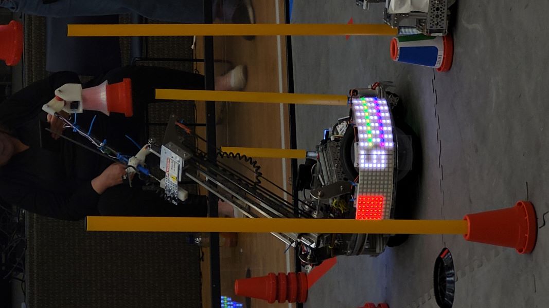
    Match 2: 68 to 63 Loss

    In the autonomous section, our robot performed great and went according to plan, scoring the preload cone and 2 more on the tallest cone and parking, equating to 35 points. However, in the tele-op and endgame, the robot’s issues reared their ugly heads. We did score one cone on a tall cone and one on a medium cone. However, after our opponent took ownership of one of our tall poles, we went for another pole instead of taking it back, and that led to us tipping over as the arm extended, which ended the game for us. We did not incur any penalties but had we scored that cone and taken back our pole, we would have won and gotten to add a perfect autonomous to our tiebreaker points. We ended up scoring 9 points in this section. Total Points: 44

    Analysis: Excellent autonomous performance marred by a tipping issue and sub-par driver performance. The anti-tipping code did not work as intended, and that issue will need to be fixed to allow TauBot to score at its entire range.
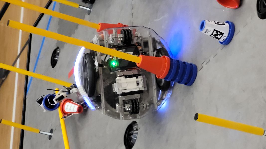
    Match 3: 78 to 31 Win

    In the autonomous section, we missed the preload cone and couldn’t grab both the cones on the stack, and we also did not park as our arm and shoulder crossed the border. As a result, we scored 0 points total in this section. In the tele-op and endgame section, we scored a lot better, scoring two cones on the tall poles, one on the medium poles, and two on the short ones. This, including our 15 ownership points, equates to a total of 35 points. Total Points: 35

    Analysis: The autonomous does need tuning to at least park because of the value of autonomous points. Our lack of driver practice is also slightly evident in the time it takes to pick up new cones, but that can be solved through increased gameplay.

    Match 4: 40 to 32 Win

    In the autonomous section, we scored our preload cone on a tall pole, but intense arm oscillation meant we missed the first cone from the stack on drop-off and the second cone from the stack on pickup. We also overshot parking again, bringing our total in this period to 5 points. In the tele-op and endgame section, we scored two cones on the tall poles. So with ownership points, our total in this section was 16 points. We did miss one cone drop-off, though, and our pickups in the substation could have been better as we tipped over a couple of cones during pickup. Total Points: 21

    Analysis: Parking still needed to be tuned, but the cone scoring was a lot more consistent, but still requires a bit more work to achieve consistency. Other than that, improved driver practice will help cycle times and scoring.

    Match 5: 51 to 24 Win

    In the autonomous section, our arm never engaged to go and score our preload, and the robot did park, meaning we scored 20 points in this section. In the tele-op and endgame section, we scored two cones on the tall poles, one cone on the medium poles, and missed three on drop-off. We also scored our beacon, bringing our total point count in this game portion to 30 points. Total Points: 50

    Analysis: Pretty solid match, but the autonomous still needs tuning, and driver practice on cone drop-offs could be better.

    Match 6: 74 to 50 Loss

    In the autonomous section, our robot missed the drop off of 2 cones but parked, bringing the total to 20 points for autonomous. In the tele-op and endgame section, miscommunication with our alliance partner led to them knocking our cones out of the substation and blocking our intake path multiple times. We scored three cones on the tall poles and missed two on drop-off. In the end, we scored the beacon, scoring 30 points in this section. Total Points: 50(we carried)

    Analysis: Communication with our alliance partner was a significant issue in this match. Our alliance partner crossed onto our side and occupied the substation for a while, blocking our human player from placing down cones and blocking our intake path. This led to valuable seconds being wasted.

    Overall, our main issues revolved around autonomous code tuning; although our autonomous performance did improve, poor driver practice we chalk up to fatigue, along with minor tipping and communication issues. However, we plan to understand what happened and solve our problems before the next week’s Tournament.

    Then, for a quick update on TauBot2, parts of the manufacturing and build have begun, and we hope to incorporate at least part of the new design into the robot we bring to the Tournament on the 28th. Currently, parts of the Chassis and UnderArm have been CNC’ed or 3D printed, and assembly has begun.
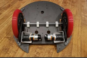
    Next Steps

    Finish up the design of Tau2 and start manufacturing and assembling it, tuning our autonomous and anti-tipping code, and attempting to get more driver practice in preparation for next week’s Tournament.
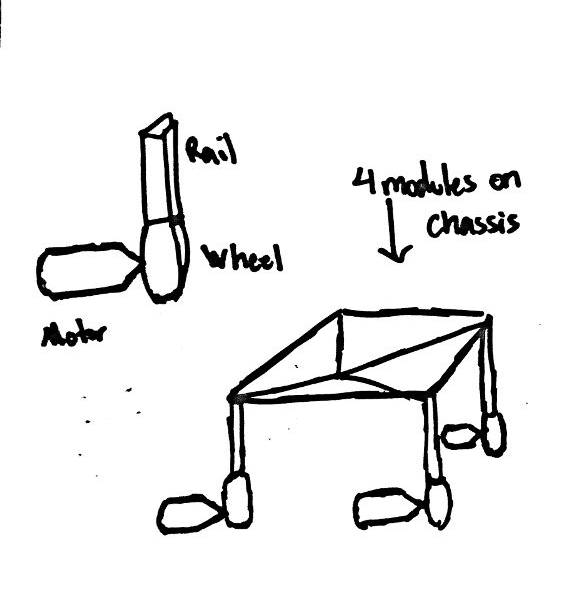
    Overview of the past 3 weeks

    Overview of the past 3 weeks By Anuhya, Aarav, Leo, Vance, Trey, Gabriel, and Georgia

    Task: Recount the developments made to the robot in the past 3 weeks

    The past three weeks have been incredibly eventful, as we try to beat the clock and finish TaBbot: V2. We had a lot of work to do in build and code, since we were putting together an entirely new robot, coding it, and getting it competition-ready for the D&U league tournament on 01/28/2023.

    Build:

    We were making many changes to the design of our robot between TauBot: V1 and TauBot: V2. We had a lot of build and assembly to do, including putting the rest of the UnderArm together, adding it to the robot, CNCing many of the carbon fiber and aluminum components and assembling the new tires. Our 3D printer and CNC were running constantly over the span of the past 3 weeks. We also had to make sure the current iteration of the robot was working properly, so we could perform well at our final league meet and cement our league ranking going into the tournament.

    Leo focused on assembling the UnderArm and attaching it to the robot. The UnderArm was fully designed, CAMed and milled prior to the tournament, but we didn’t get the chance to add it to the robot or test the code. We were still having a problem with the robot tipping over when the Crane was fully extended, so we decided to attach the omni wheels and “chariot” for the UnderArm to the robot, to counterbalance the Crane when it was fully extended. We experimented with it, and this almost completely eradicated our tipping problem. However, while testing it separately from the robot, we got an idea for how the UnderArm would work with the Crane, and how we should begin synchronizing it.

    Because the majority of the new iteration of Taubot is entirely custom parts, designing the robot was all we had the chance to do prior to the tournament. However, we managed to get the basic chassis milled with carbon fiber and a sheet of very thin polycarbonate. We also began assembling parts of the new Shoulder and Turret assembly, but decided to not rush it and use the old assembly with the new chassis of Taubot: V2.

    Before the tournament though, we incorporated the new UnderArm assembly, carbon fiber chassis, and newly-printed TPU wheels with the Shoulder, Turret, and Crane from TauBot in preparation for the upcoming tournament.

    Code:

    On the code side of things, we mainly worked on fine tuning the code for the scoring patterns and feedforward PID. Most new things which we will be adding to our code will be done after we have completely attached the UnderArm to the main body of Taubot: V2, because that is when synchronization will occur.

    Vance updated auton so it would calculate how many points were feasible and go for the highest scoring option after 25 seconds. He also sped up auton, so it wouldn’t take as long to get a cone and score it. The preloaded cone was scored consistently, but grabbing new cones from the conestacks and scoring them was still unreliable.

    When he wasn’t making auton more stable and reliable and working through the scoring patterns, Vance was working on coding the parts of UnderArm which would be independent of the rest of the robot. He added a simulation so it would be possible to test UnderArm off the robot, and changed UnderArm servo calibration. Limits were also added to UnderArm so it wouldn’t continuously loop through itself.

    Next Steps:

    We need to perform well at the Tournament to ensure our advancement. If all goes well there, the next steps would be a Post-Mortem and the continued development of TauBot2 and the portfolio in preparation for either a Semi-Regional or Regionals.

    D&U Tournament Play by Play

    D&U Tournament Play by Play By Aarav, Anuhya, Gabriel, Leo, Vance, and Trey

    Task: Narrate the events of the D&U Tournament

    Today, Iron Reign and our two sister teams competed in the D&U League Tournament at Woodrow Wilson High School, the culmination of the previous three qualifiers. Overall, we did pretty well, winning both Inspire 1 and Think 2, which means we will be directly advancing to the Regional competition in about a month. There will be a separate blog post about the tournament Post-Mortem, and this post will cover the play-by-play of the matches.

    The robot we brought to the tournament was a mix between TauBot V1 and V2, with the V2’s Chassis and UnderArm and the V1’s Turret, Shoulder, and Crane. Unfortunately, there were some robot performance drop-offs, as we slipped from 5th to 9th in the qualification standings, going 2-4 overall at the tournament.

    Play by Play

    Match 1: 84 to 17 Win

    In autonomous, due to arm wobble, we missed both the preload cone on drop-off and the cone on the stack during pickup. However, the robot was still about to get parking. Then in the tele-op and endgame, our robot scored three cones on the tall pole and one cone on the medium cone. However, rushing during cone drop-offs led to us missing a couple, and a decent amount of time was wasted during intake and arm movements. Finally, we also scored a beacon. Overall, this was a solid match, but there could be improvements. One important thing to note was that the UnderArm almost went into the substation while the human player was inside due to an issue with the distance sensor that regulated chassis length. This is something that we will have to diagnose and fix quickly.
    Match 2: 86 to 48 Loss

    In the autonomous section, our robot almost collided with an opposing robot when attempting to score the preload cone. In the end, we did not score any cones and lost parking when the UnderArm did not fully retract and traveled past the edge of the area. In the tele-op and endgame, our robot scored two cones on the tall poles and one on a medium cone. However, poor gripper positioning on intake led to time-wasting as cones kept getting tipped over, and we missed a low cone on drop-off due to rushing. In addition, the LED battery went out during the match, which could have caused a penalty and is starting to become a recurring issue. Finally, we lost due to the 40 penalty points that we conceded by pointing at the field during gameplay four times, which was a major mistake and should serve as a valuable lesson for the drive team. Overall, this match was messy and a poor showing from both our drive team and robot.

    Match 3: 74 to 33 Loss

    This match did not count toward our ranking since we were filling in. Regardless, we didn’t view this as a throwaway game. In autonomous, the robot got off track when driving toward the tall pole to drop off the preload, meaning the entire autonomous section got thrown off. We didn’t score any points or park at all. Then, in the tele-op and endgame section, a major code malfunction threw off the arm for a while. We missed multiple cone intakes by overshooting the distance, and the arm was frequently caught on the poles. Our human play was also quite sloppy and there were a few times we got close to being called for a penalty for the human player being in the substation at the same time as the robot. In the end, we only scored 1 cone on a tall pole in this section, and luckily this game did not count towards qualification rankings, but it did reveal a code issue that we quickly corrected.

    Match 4: 97 to 18 Loss

    In autonomous, our robot got bumped, missed both cones, and did not park because the arm and shoulder ended up outside the zone. Then, in the tele-op period, quickly into the start of the driver-controlled proportion, the servo wire on our bulb gripper got caught on our alliance partner’s robot. This caused the plate on which the arm was mounted to bend severely and left us out of operation for the rest of the match. Immediately after, we had to switch to the arm and gripper for TauBot2 that we had assembled but not yet attached, and this required slight modifications to the shoulder to allow all the screw holes to align. Thankfully we were able to get it working, but we faced issues later on with the movement of the new gripper limiting our cone intake.

    Match 5: 144 to 74 Loss

    In autonomous, the arm wobble caused our preload to drop short, but we parked. We also accidentally “stabbed” our opponent’s preload cone out of their gripper when they were about to score it. Since this was in autonomous, we were not penalized, but it was quite funny. However, in tele-op and endgame, we missed multiple cone pickups and drop-offs and went for the cone stack instead for intaking at the substation, which was a major tactical blunder and increased our cycle times. We did score two cones on the tall poles and one cone on a small pole that allowed us to break our opponent’s circuit at the very end, but we still lost. Overall not a bad game, but we had a questionable strategy, and the pains of a newly assembled robot did show.
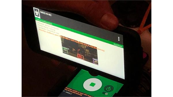
    Match 6: 74 to 66 Win

    This match was a great way to end the qualification matches, as we escaped with a narrow and intense win. Because our left-side start code was broken and our alliance partner heavily preferred standing on the right side, we started our robot on the right and stood on the left, which was quite a novel strategy. It did come with drawbacks, as during the start of tele-op, we wasted valuable seconds crossing the field with our robot. Anyways, in autonomous, major arm wobble led to us missing the preload by a mile, the stack intake code was off, and we did not park. Tele-op and endgame were quite an intense competition, and we scored three cones on the tall poles, including a clutch beacon cone in the last 10 seconds of endgame to win the game. Overall this was a great game, although we still had autonomous issues, and it was a good ending to an overall poor run in qualifications.

    We ended the qualification portion with an overall standing of 9 and a record of 12-3. Thanks to good connections with our fellow teams, we were picked by the 3rd-ranked alliance as their 3rd pick. Therefore, we did not play the 1st match of the semifinal, which we lost, but we did play the 2nd match.

    Semifinal 2 Match 2: 131 to 38 Loss

    In autonomous, the arm wobble led to us missing the preload and the cones from the stack, and we did not park either. Then, during tele-op and endgame, we scored one cone on a tall pole. Unfortunately, though, our alliance partner’s robot tipped over during intake, which led to ou5t gripper getting stuck to their wheel and causing yet another entanglement. This led to the shoulder axle loosening, and the entire subsystem became unusable after the match. This isn’t that bad since we plan to replace that with the new, redesigned Turret, Shoulder, and Arm, but it wasn’t the best way to go out.

    Overall, though, we did okay, considering we were running a new robot with a partially untested subsystem in the UnderArm and still won a few matches and made the semifinals. In the end, though, our portfolio and documentation pulled through as we won Inspire. However, this tournament exposed many flaws and issues in our robot, which will be discussed in the Post-Mortem Blog post, and we will need to fix these issues before Regionals next month.

    D&U League Tournament Post Mortem

    D&U League Tournament Post Mortem By Anuhya, Georgia, Gabriel, Trey, Vance, Leo, and Aarav

    Task: Discuss the events of our first tournament of the season

    Team 6832, Iron Reign, and our sister teams, Iron Core and Iron Giant had our first tournament to qualify for Regionals or Semi Regionals. Overall, it was an incredible learning experience for our newer members. This was our first opportunity this year to talk to judges and leave a lasting impression with our presentation skills and our robot.

    Strengths:

    • The speed and success with which we replaced the gripper
    • We won Inspire and 2nd place Think so our portfolio was definitely well constructed
    • We did a good job of selling the team's story, its role in the larger ftc community, and how tau is the pinnacle of that story

    Weaknesses:

    • Less emphasis on outreach
    • Distance sensor detected wire, messed with underarm
    • Need new place to mount power switch to make room for underarm
    • Coordinating with alliance partners
      • Collisions were avoidable, high scores more achievable
      • Have to get better at concisely explaining strategy, maybe with a short video
    • Drive Practice: Not enough, excusable since it was a new robot, but not going forward
      • Time to train with multiple drivers for scoring patterns

    Opportunities:

    • UnderArm
    • New Crane which can extend farther
    • A more versatile gripper: Flipper Gripper
    • Prioritize presentation for proper emphasis
    • Mechavator reveal video
    • Taubot Reveal Video
    • Subsystems video
      • Linear slide video
    • STEM Expo
    • Better cable management
    • Reliable UnderArm distance measurement - need ideas
      • Odometry wheels on linear slides
      • Encoder on a spring-powered retractable string (like the ones you would use for an id badge)
      • Tape measure with sensor to read numbers
    • Using sensors for autonomous period and tele-op

    Threats:

    • Robot capability
      • Release the Flipper Gripper - we need to see the dynamics in action, it might not be viable
      • Flipper gripper damping - we need to try different friction materials
      • Bulb gripper wrist - we may need to do active wrist control, which needs to be figured out asap
      • Flipper Gripper elbow - we may need to do active elbow control, which needs to be figured out asap
      • New Crane/Shoulder/Turret - need to avvelerate the build
      • Crane bouncing needs to be fixed on the new system
      • New Crane wiring harness with distance sensor and 3 servos - can't wait for full custom board manufacturing - need prototype
      • New IMU for new Crane (ordered)
      • Nudge stick distance sensor - will it work over the ultra long cable?
      • UnderArm
        • Mount onto robot and get unfold and articulations right
        • Anti-collision code with Crane
        • Better distance sensing and control for chariot extension
        • May need wrist control for conestacks
      • Lasso gripper needs to be tested, might not be viable
        • Make an alternate gripper design for UnderArm, as a fail-over option
      • Sensors
        • Cone and Cone Stack detector
        • Junction pole detector
        • Differential Distance Sensor as alternative to vision
        • Team number labels if LED Panels get rejected
        • Huge amount of drive practice needed
    • Team Composition - will onboarding new members at this time cause confusion and harm productivity?
    • Teams
      • Technic Bots
      • Mark X
      • Technical Difficulties
    • New sponsors and connect opportunities
    • Prep
      • Poor battery planning
        • Missing a multimeter
        • LED panel batteries not charged
        • Batteries not properly labeled
        • LED Switch and battery not properly secure
        • Batteries need to be tested for internal resistance
      • Rank what would be best to talk about, so talk about what benefits our stationary robot
    • Judging
      • Didn't have powerpoint up for initial judge motivate
      • More practice/preparation beforehand
      • Lack of presentation practice and timing(couldn't finish connect and motivate)
      • Don't oversaturate with information/gloss over other parts
      • Lack of people ready for judging panels
      • Lack of enthusiasm
      • Need Cart with display ready to go
      • Practice entering the room with the robot running
      • Practice in-judging Demo
      • Whenever we mention a specific part of subsystem, let judges interact with it
    • Inspection
      • Capstones were too close to being out of sizing - reprint
      • Robot close to out of sizing (Inspector was young, careless, and did not thoroughly check sizing)
      • Missing power switch label and full initialization label (they let us replace it, it was fine)

    UnderArm Inverse Kinematics

    UnderArm Inverse Kinematics By Jai, Vance, Alex, Aarav, and Krish

    Task: Implement Inverse Kinematics on the UnderArm

    Inverse kinematics is the process of finding the joint variables needed for a kinematic chain to reach a specified endpoint. In the context of TauBot2, inverse kinematics, or IK is used in the crane and the UnderArm. In this blog post, we'll be focused on the implementation of IK in the UnderArm.

    The goal of this problem was to solve for the angles of the shoulder and the elbow that would get us to a specific field coordinate. Our constants were the end coordinates, the lengths of both segments of our UnderArm, and the starting position of the UnderArm. We already had the turret angle after a simple bearing calculation based on the coordinates of the field target and the UnderArm.

    First, we set up the problem with the appropriate triangles and variables. Initially, we tried to solve the problem with solely right angle trigonometry. After spending a couple hours scratching our heads, we determined that the problem wasn't possible with solely right angle trig. Here's what our initial setup looked like.

    In this image, the target field coordinate is labeled (x, z) and the upper and lower arm lengths are labeled S and L. n is the height of the right triangle formed by the upper arm, a segment of x, and the height of the target. m is the perpendicular line that extends from the target and intersects with n. We solved this problem for θ and θ2, but we solved for them in terms of n and m, which were unsolvable.

    After going back to the drawing board, we attempted another set of equations with the law of sines. More frustration ensued, and we ran into another unsolveable problem.

    Our Current Solution

    Finally, we attempted the equations one more time, this time implementing the law of cosines. The law of cosines allows us to solve for the side lengths of non-right triangles.


    Using this, we set up the triangles one more time.

    Our goals in this problem were to solve for q1 and for α.

    We quickly calculated a hypotenuse from the starting point to the target point with the Pythagorean Theorem. Using the radius and our arm length constants we determined cos(α). All we had to do from there was take the inverse cosine of that same equation, and we'd calculated α. To calculate q1, we had to find q2; and add it to the inverse tangent of our full right triangle's height and width. We calculated q2 using the equation at the very bottom of the image, and we had all of the variables that we needed.


    After we solved for both angles, we sanity checked our values with Desmos using rough estimates of the arm segment lengths. Here's what the implementation looks like in our robot's code.

    Meeting Log 2/17

    Meeting Log 2/17 By Aarav, Anuhya, Jai, Alex, Tanvi, Georgia, Gabriel, and Krish

    Work on build, code, and presentation in preparation for Regionals next week.

    With the Regional competition coming up quite soon, we needed to get to work finishing up the build for TauBotV2, optimizing the code with new inverse kinematics for the double-jointed UnderArm, finishing up some subsystem blog posts, and practicing and preparing our presentation.

    Presentation:

    With a heavily below-par performance than the Tournament presentation where we skipped the entire Connect and Motivate section, we needed to stress practicing the performance this go around. We condensed the information into quick lines for each slide, but also expanded the overall amount of content to allow us flexibility.

    After that, we got in valuable presentation practice to ensure that we don’t run over the 5-minute mark and miss out on sharing valuable information to the judges. At around a medium-ish pace, we finished the entire presentation in about 4:15. Pretty good, but that does mean that a few more slides of content could be added to maximize the time.

    Build:

    The new shoulder, turret, and linear slides need to be fully assembled and attached to TauBot2. We made the decision to move the entire shoulder assembly up a centimeter because of size restrictions and requirements, which meant we needed to reprint most of the motor mounts for the extension and rotation motors. We also finished assembling together all the linear slides and their carriages.

    Code:

    This is where most of the progress for today was made. Because of the double-jointed nature of the UnderArm crane, we needed new inverse kinematics equations in order to derive the proper angles for both sets of servos. From a given (x,y) point and the constants a1 and a2, which each refer to the length of each section of the crane respectively, we should be able to calculate the requisite servo angles. Through both right triangle trig and the law of cosines, we could find angle ɑ, the angle for the servos mounted by the turret, and angle β, the angle for the servos mounted between the two sections. This should allow us to move the crane to any position we desire simply with a set of coordinates.

    We plugged both equations into Desmos to find the acceptable movement distances for the entire crane and added these calculations to the codebase, although we were not able to test them tonight. This is sort of a brief overview, but there will be a more detailed blog post covering the inverse kinematics of the UnderArm soon.

    Next Steps:

    With Regionals next week, we need to finish the full build of TauBot2 and begin coding the UnderArm so our two “intakes” can work together effectively in union. The UnderArm is still heavily untested, and there is a chance it fails miserably, so we need to start working on ironing out its issues and getting the entire robot to a functional state where it can cycle and score a few cones as intended. Our portfolio still needs to be converted into landscape and additional content added to fill up the vast amounts of empty space that remain. We also need to start working on possibly designing a custom binder out of carbon fiber to house the entire portfolio. With only a week left, we need to start acting now in order to finish everything before Regionals. The presentation is also a little bit low on content and slides, especially for pit interviews and Q&A, so we will be transferring more of the portfolio content to the presentation. To be competitive at Regionals for an award and advancement, we will need to tier documentation, which means sorting out any potential issues and lots of effort and practice. Overall, we made lots of progress, but there is still a lot of work left to be done.

    NTX Regionals Post-Mortem

    NTX Regionals Post-Mortem By Aarav, Anuhya, Georgia, Gabriel, Trey, Vance, Alex, Krish, and Jai

    Discuss the events of Regionals, analyze our performance, and prepare future plans

    This past Saturday, team 6832 Iron Reign participated in the NTX Regionals Championship at Marcus High School. Overall, despite some robot performance issues, we won the Motivate award, meaning we advanced to both the UIL State Championship and FTC State Championship. Today, 2 days after the competition, we had our Regionals Post-Mortem, and below are our main strengths, weaknesses, potential opportunities, and threats.

    Strengths:

    • Motivate game was quite strong -> Figure of 1500 kids at two outreach events was quite impactful
    • Presentation
      • Should work on arrangement of members, some were off to the side and couldn’t do their slides -> Potentially utilize CartBot and a monitor
    • Meeting with judges went generally pretty well
    • Portfolio is quite well constructed and unique
      • Well-practiced portfolio/presentation team(lots of improvement from last time)
    • Shoulder of the robot was strong
      • Rails were bending; tension too tight.
    • Switching to carbon fiber resulted in a far stronger robot that did not crack
    • Turret was much more capable of moving the extended crane
      • Even worked well in fast mode -> probably could increase the speed of our articulations

    Weaknesses:

    • The need to sleep
    • Team burnout
    • Significant under planning
    • Entanglement of springy cable on junctions during auton
      • Arm does wide arcs sometimes, articulations not working half the time
    • Lack of driving practice
    • Cone placement accuracy
    • Navigation to final position speed
    • Connect game compared to other top teams
    • Turning down an Innovate panel
    • Robot Demo in judging
    • No reliable auton
      • If auton goes bad, effects extend into tele-op. The dependence is nice when auton is working but a hindrance when it needs to work.
    • No reliable wheels that rotate straight which messes up auton
      • Underarm wheels not working well and the cable management is still out of wack
    • Placement of certain components on the robot
    • Should have made it more clear to new recruits that this was crunch time and expectations for attendance are way up
    • Coordination in pre competition prep
    • Our funding situation is really bad. We are way over extended on deficit and Mr. V is not putting more money in

    Opportunities:

    • Booth at the pits with detailed banners
    • Good robot == good judging
      • Completing the robot puts us in the running for more technical awards
    • Build Freeze
    • A fully functioning robot with the transfer that can win matches would put us in Inspire contention somewhat
      • Synchronization with transfer would be impressive in a control sense as well
    • Strengthening our motivate outreach
    • Spring Break
    • A larger team to better spread the workload leading up to State
    • Curved Nudge hook
    • Drive practice
      • Need more on the left side. We are becoming a liability for our partners to side limitations in terms of driver practice.
    • Code Testing
    • Maintenance for parts that were previously underdone/not to our standards
    • Live robot demo
    • Time to improve our connect game
    • Judges for control award wanted to see more sensors
      • Nudgestick + cone gripper
    • Mechavator Reveal
    • Cart Bot
    • Matching shirts and hats

    Threats:

    • Our Connect game is significantly weaker than the competition
    • Technic Bots won Inspire twice
      • They had good outreach as well
      • They also have an underarm & it is very much working well
    • We have 3 weeks to code an entire robot
    • 9 advance from state to worlds so we cannot rely on Motivate again, we need a stronger award, also most likely cannot just place 2nd for any award so Think Winner should be our absolute minimum goal or Inspire 3r
    • Mr. V unavailable for a number of days leading up to State

    Control Award Video

    Control Award Video By Trey, Vance, Jai, and Anuhya

    Texas State and UIL Championship Post-Mortem

    Texas State and UIL Championship Post-Mortem By Aarav, Anuhya, Georgia, Gabriel, Trey, Leo, Vance, Alex, Krish, Jai, and Tanvi

    Discuss the events of Regionals, analyze our performance, and prepare future plans

    This weekend, Iron Reign participated in the FTC UIL Championship, which was mainly robot game, and the FTC Texas State tournament, where we advanced to FTC Worlds with the Think award, an award granted for the engineering portfolio and documentation. We learned a lot from our gameplay and communications with our alliance partners, and got the chance to see our robot in action properly for the first time. This is our analysis of our main strengths, weaknesses, and future opportunities and threats we will have to deal with before competing at Worlds.

    Strengths:

    • fast maintenance when things went wrong, both build and code related
    • sticking to our own strategy
    • being able to access all the junctions/ cover a lot of ground
    • communication with alliances
      • not being a hindrance to our alliance partners

    Weaknesses:

    • penalties for wrapping around poles and extending out of field
    • long time required to recalibrate if setting up goes wrong
    • no consistent gameplay
    • turret movement is very choppy
    • lack of time to modify UnderArm
    • less time for testing because of complicated design
    • cone gets dropped, especially during transfer

    Opportunities:

    • further optimizing transfer and transfer speed
    • working on auton parking and cone scoring with transfer
    • automating transfer
    • we will have time to further finetune the robot

    Threats:

    • Nudge Stick is still a hindrance to game play
    • lack of drive practice because design was prioritized
    • robot pushes itself past what is mechanically possible
    • robot relies on calibration, which isn't convenient

    Meeting Log 4/1

    Meeting Log 4/1 By Sol, Georgia, Trey, Anuhya, Gabriel, Leo, Krish, Tanvi, Jai, Vance, Alex, and Aarav

    Task: Gripper Redesign and Build Fixes

    Trey redesigned the gripper stopper on the underarm to limit the degrees of movement so that the underarm gripper will not get stuck. The original design of the gripper stopper did not fully stop the gripper because it did not limit the gripper's movement as much as we wanted it to.

    The tensioning belt on the shoulder attached to the crane became too lose, and started skipping at lot, so Krish and Georgia re-tensioned it again by moving the motor on the turntable farther away from the other.

    The omni wheels on the bottom of the underarm kept breaking, so we replaced them, and worked on ideas about how to stop breaking the wheels. We figured out what was happening was that there was so much pressure being put on the wheels that the spokes for the small wheels kept falling out of the seams. The problem with this was that the wheels would damage the field, and the underarm wouldn't smoothly move across the field. To solve this problem, we melted the plastic so that the seams were no longer open and the spokes wouldn't be able to fall out.

    Our code team continued to tune and debug autonomous, while our build team asynchronously worked on the robot. Later, Georgie and Tanvi worked on pit design for Worlds. They designed the pit and figured out how much it would cost. After deciding on what materials we would need, they reached out to companies to ask about sponsorships. In addition, we worked on updating our portfolio and designing banners for Worlds.

    Next Steps:

    Our next steps are to continue tuning code, more drive practice, and finish pit design.

    Meeting Log 4/9

    Meeting Log 4/9 By Georgia, Sol, Trey, and Leo

    Task: Prepare for Worlds through Build and Drive

    Today, we did drive practice, and worked out some of the smaller issues with transfer.

    While doing robot testing, the servo on the underarm shoulder joint broke. We took apart the joint in order to fix the servo, but the servo's gearbox was not accessible, rendering us unable to diagnose the problem, so we had to replace the old servo with a new one.

    Trey redesigned a new transfer plate bridge, then milled it on the CNC. While milling this piece, we pushed the CNC too much, causing a drill bit to break. After that, we cut the part again, but the cutouts got caught between the drillbit and the plate, causing the CNC to crash. Twice. Eventually, we fixed the issues, and successfully cut out the new transfer plate bridge.

    By the end of the meeting, we had successfully tested underarm.

    Next Steps:

    Our next steps are to finish making transfer work, remove the shoulder support spring, get more drive practice, and prepare for State and UIL.

    Consequences of Removing the Shoulder Support Spring

    Consequences of Removing the Shoulder Support Spring By Anuhya, Trey, Leo, Gabriel, and Vance

    We learned the consequences of making small changes to build without fully knowing the outcome

    A small change can make a huge difference: we have learned that we really should have put the shoulder spring back in place after we rebuilt Taubot. The Crane arm fails to maintain its shoulder angle, and this is an issue which has only started since we built Tau2. We're probably hitting the thermal cutoff for the motor port, which causes the control hub to stop sending power to the shoulder motor and the whole arm crashes to the ground.

    This also means that its stalling the motor and it pulls a huge amount of Amps. We also have horrendous battery management, which leads to short battery life and permanent battery damage. The Crane being held out fully extended further damages it.

    A lot of Tau2 is an inherited, yet modified, design. We aren't fully aware of the considerations that caused a spring to be in Tombot, the original robot we based part of our design on. We also changed the gear ratio of the shoulder motor so we could power through lifting the shoulder at extremes, and we're pulling many more electrons to compensate for something which was built-in initially.

    The original reason was a design goal - whenever you make an arm, you want as little motor force as possible dedicated to maintain the arm against gravity. The motor should just have been changing the position, not maintaining it. Real world cranes use counterweights or hydraulics to fix this problem, something which we don't conveniently have access to.

    The spring was meant to reduce the burden of maintaining the crane's weight against gravity. It wasn't perfect by a long shot, but it definitely did help. Our batteries would also last longer in matches and have a longer life.

    Thankfully, we still have access to the original CAM we used for the log spiral, and a spring could easily be reintroduced into our robot if we messed with some of the wires. It's a high priority and needs to be done as soon as possible.

    However, hardware changes like these are incredibly annoying for coders. We recently added a custom transfer plate too, and it was very helpful to increase transfer efficiency. It also changed the angle of the initial transfer plate to the flipper gripper, which added 3 hours of extra coding time to retune transfer and grasping the cones so it didn't get knocked off. It will be better once fully tuned, but it doesn't change the fact that small changes in physical build are incredibly annoying for the coding team. Adding the shoulder support spring will also have this kind of cost, but it's crucial for further success.

    Scrimmage Before Worlds

    Scrimmage Before Worlds By Anuhya, Jai, Alex, Trey, Gabriel, Vance, and Leo

    Attending a Final Scrimmage Before Worlds

    Today, we attended a scrimmage that team 8565, Technic Bots, graciously invited us to. The point of this scrimmage was to get some time seeing the changes which the other Worlds-advancing NTX teams had implemented, and to get some ideas of strategies and alliances. This was the first time we were able to get proper driver practice with the newly designed Transfer Plate and Nudge Stick.

    One of the main problems we experienced was our cable harnesses malfunctioning. The servos kept getting unplugged or the signals just weren't sending properly, which was a large issue. This meant that our Gripper Flipper assembly wouldn't flip into place, so the cones which the UnderArm was depositing onto the Transfer Plate would remain on the Transfer Plate and act as a hindrance. This also increased the chances of double cone handling, which is a major penalty. The Bulb Gripper was unable to get cones off the Transfer Plate because the servo which controlled the Gripper Flipper wasn't working. However, we learned that UnderArm to Transfer Plate mechanisms worked incredibly effectively and consistently.

    We also learned an important lesson about calibration; without realizing there would be consequences, we started calibration of our robot with the robot in the starting position, against the walls of the playing field. During calibration, the Turret does a full 360, during which the nudge stick kept hitting the walls of the playing field, causing one end to completely snap off at the joint which connected the REV channel to the nylon.

    The scrimmage also gave us a chance to work on auton. During our autonomous drive, we use a timer separate from the one on the driver station to make sure that we can complete or abort our auton safely before the driver station timer kills power to our robot. In our auton testing, we found that this time-management system was not properly iterating through the stages of our autonomous. To solve this, we reviewed and edited our code to work with our timer system and performed repeated trials of our autonomous system to ensure reliability. Once we fixed these bugs, we had the chance to begin working on improving the accuracy of our parking procedure. Our parking procedure hadn't been modified for our new cone-stack-dependent autonomous strategy, so we changed the code to account for it. We are now well on the way to a consistently performing autonomous mode.

    Next Steps:

    We will continue working on building and code, especially auton. We need to make sure that our Nudge Stick works in practice, and we need to make sure our drivers get time to get used to having a Nudge Stick to control. Overall, we need drive practice, and we need to make parking and getting cones from cone stack consistent in our autonomous period.

    FTC World Championship 2023

    FTC World Championship 2023 By Anuhya, Jai, Alex, Trey, Gabriel, Vance, Leo, Tanvi, Georgia, Krish, Arun, Aarav, and Sol

    Our Experience This Year at Worlds

    Over this past week, we had our final preparations for the FTC Worlds Championship in Houston, Texas, which was our final destination after everything we’d done this season. This Championship was an incredible opportunity for us to interact with teams from around the world, and establish relationships with teams we never would have been able to meet otherwise. It was an incredible outreach opportunity, where we talked to teams from Romania, India, Libya, and other countries with different approaches to how we did robotics. At the Regional Edison Awards, we won 2nd place Motivate!

    What was productive at worlds?

    The build of the robot was much closer to being done than it had been at previous tournaments. We were also relatively confident in the capabilities of our transfer system, especially with the implementation of the Transfer Plate. We were also prepared with replacement parts fully made and manufactured, so we knew we would be able to replace the UnderArm if something went wrong with one of the arms.

    What was beneficial to our team?

    The time and effort we put into our portfolio as a team was definitely one of our strongest points. We were prepared for how to interact with judges, and we had also practiced our answers to some possible questions we could get. By showing the judges how our team was set up and the true nature of our compatibility and cooperation, we were able to leave a lasting impression.

    We also had a pit design which was made to help our productivity, with shelving to organize our tools and supplies, tables set aside for different purposes and stools to maximize space within the tent. It also helped us convey a good team image to the other teams who were present at Worlds, and gave us a place to talk about our robot design and game strategy. The posters which were put up in our pit were also very effective, because they were great conversation starters. Teams were very interested in seeing our robot design and getting an explanation for some of our decisions when they saw the engineering banners which were put up at eye level.

    How do we want to improve?

    One large issue that we had throughout the entire season was our robot was never fully prepared when it was time for the tournament. We didn’t have the opportunity to have driver practice throughout the season, especially with the new robot and the new design, so we found a lot of issues at the actual Worlds Championship that we should have found and fixed way earlier. We also burnt out many of our axon servos at the tournament, and scrambling to find more because they were the basis of our UnderArm was not a good look for the team. One of our primary goals for next year will definitely be finishing the robot on time, so our drivers have a good opportunity to get drive practice. At the Championship, we also barely passed inspection. Because we didn’t have enough time to ensure that our robot fit under sizing when it was initialized, we had to get inspected a second time. Overall, we want to make sure that we are fully prepared for all tournament procedures in the upcoming season, so we don’t have as much of an issue during the actual tournament.

    Our packing and organization also left something to be desired, because we didn’t start packing until 1 or 2 days before the tournament. While our pit design was effective, we didn’t have a chance to practice it beforehand, and we could have made some design changes and improvements if we had practiced it prior to the tournament. Even though we had shelves, it took us 20 to 30 minutes to find tools and that was incredibly frustrating when we were in a time crunch.

    Something else we were lacking in was communication between different subteams. One of our largest problems was that the coders weren’t given enough time to work on the robot because the modelers and builders weren’t entirely sure about when prototypes would be available. We also sacrificed a lot of sleep because we weren’t ready to compete when tournaments came around, and it wasn’t sustainable throughout the year and led to a lot of burnout. Our morale was also low because of deadlines and not having a sustainable work ethic.

    Next Step:

    The next season started the day Power Play ended. Over the summer, we have plans to start recruitment and outreach early, and set up boot camps to get the new members of our team more specialized and ready for the next season. We also wanted to get the MXP up and running, so we would have more mobile opportunities to teach kids how to code and use 3D printers and just set up more outreach events. We’ve also started setting up organization softwares and setting up different team roles to maximize organization in the following seasons.

    Iron Reign’s R2V2 - Safety Features and Protocols

    Iron Reign’s R2V2 - Safety Features and Protocols By Coach

    Let's robotify this!

    What if you took an RV, converted it into a mobile learning lab, and then turned that into a droid? What would you call it? We call it R2V2

    Intrinsic Hazards and Safeties
    Primary Safety
    Backup Safety
    Site Safety
    Operational Safety

    Intrinsic Hazards and Safeties

    Intrinsic Hazards

    It’s important to keep in mind that our mobile learning lab is based on a Class A motorhome chassis. As such it weighs on the order of 16 tons and represents a real danger with any kind of untrained operation. There is no place for any lack of vigilance and caution for safely operating this vehicle.

    Intrinsic Safety

    R2V2 has multiple emergency stop overrides and we employ them redundantly in fail-safe modes. The only intrinsic safety lies in the reliable slow motion of the vehicle with max speed under normal human control. The engine will only be run at idle speed and the PSO will only apply acceleration if needed to get the vehicle moving at a walking pace ground travel speed. The acceleration pedal is not automated. People in the test zone will still need to maintain safe distances. Therefore, we have established Operational Safety and Site Safety protocols.

    Primary Safety Operator

    The Primary Safety Operator (PSO) is our coach, who is the owner and operator of the vehicle and who will always be behind the wheel while the vehicle's engine is on. Only he has the authority to start the engine and operate the gear shifter. He also has the ability to physically override the primary brake and independently operate the parking brake. He is the only one able to apply any force to the accelerator via normal foot control. He is also able to kill power to the whole control system, thereby engaging passive braking and locking the steering.

    Remote Safety Operator

    The remote safety operator will be a student trained and solely assigned the task of the ensuring safe operations from the outside. Their mandate is to stop the vehicle if they see anything wrong. Their interface is a normal gamepad where they have only two controls, either of which will stop the vehicle. The left trigger is configured as a deadman switch and has to be held in order for unbraking (and therefore motion) to happen. They can also press the red button on the gamepad to stop the opmode, thus idling the unbrake.

    Remote Driver

    The remote driver also has access to a kill button on their gamepad. They are responsible for starting and stopping automation by controlling the opmode. They can engage in remote steering or enabling automated steering, and can unbrake the vehicle, thereby allowing overrideable movement.

    Fail Safes

    • The brake and steering are the only two systems under automation.
    • The brake is the real safety system and is designed to fail into braking mode. The brake pedal is continually pushed toward stopping the vehicle by rugged bungees.
    • Unbraking or counter-braking requires a motor to counteract the passive bungee tension and allow the brake pedal to release.
    • If power fails to the counter braking motor, the tension in the bungees is enough to back-drive the motor and apply pressure to the vehicle's brake pedal.
    • If the control system locks up with counterbraking applied and doesn't respond to any of the kill commands, the Primary Safety Operator still has the ability to overpower the counterbrake motor. The motor simply doesn't have the torque needed to compete with a human leg. As stated elsewhere, 3 people have access to multiple means of shutting down the control system and we find this extremely unlikely, but are keeping this potential failure mode in mind.
    • The steering motor simply locks up in any kind of failure mode. The gear ratio is approximately 200:1 and the gentle natural tendency of the steering column to center when no input is applied is insufficient to back-drive the steering input. There are too many factors to decide how steering should be applied in an emergency situation. So we decided to take steering out of the equation and simply rely on stopping the vehicle while locking the steering motor. Removing power, killing the opmode and not receiving continuous unbraking commands all result in engaging braking and locking steering to the current angle.
    • All of the above are testable both off the vehicle and while installed.
    • We can’t say it’s impossible for the control software stack to crash in a state where it continues to send a safety-disengage PWM position signal. We’ve never seen it happen and we believe it’s prevented by the interaction of the firmware and the app – but we can’t say it’s impossible. It’s also possible to imagine a freak condition where the servo gearbox breaks and locks up in the safety-disengaged position. So we decided to create a redundant backup safety.

      Site Safety

      Site safety speaks to conditions of the site and surrounding properties that informs the risk to people and property.

      The site is the backyard 3 acres of our coach’s residence and the primary structure on the site is the home itself (blue oval, below). The site slopes downhill fairly steeply from the back of the house to the creek that cuts all the way across the property at the bottom (right side in the image). The site is heavily forested with the exception of an open glade, a clearing for a future workshop, and a gravel driveway connecting them uphill to the main driveway for the residence.

      With the exception of the driveway, the open areas are surrounded by impassable forest (yellow line in the overhead shot below). By impassible we mean that the R2V2 would stall on trees and undergrowth within 10 feet if it tried to push through the surrounding brush. In addition to the forest/undergrowth, all of the neighbor’s properties are further isolated by being either significantly upslope or on the other side of the creek. The creek has cut an impassable 20 foot sudden drop across the property’s southern border, effectively creating a moat that would protect the only neighbor property that is downslope. Right now there is no path to the creek that R2V2 could take.

      The future workshop site (white oval) is the only area that the R2V2 will be allowed to operate in. The ground there is mostly level and compacted. Still, team members need to keep this area clear of possible stumbling hazards. We will refer to this area as the arena.

      Operational Safety

      Operational Safety consists of the training and protocols that will be followed to assure minimal risk to the participants.

      • R2V2 will only be operated on a closed course like the arena. Closed means that we have good control and awareness of all souls on a private course and no other vehicles are moving.
      • Our coach will always be present and supervising operations. The vehicle will only be started by coach.
      • There will be a minimum of three operators, the Primary Safety Operator, a Remote Safety Operator and a Remote Driver. These roles were defined above.
      • Additional spotters will be able to call out safety concerns by issuing a Halt call and hand signal.
      • Every session will begin with a meeting to discuss all planned movements to be sure that everyone in the area knows what to expect as well as what could go wrong and to address specific safety concerns.
      • While we may use "movie magic" to make it appear otherwise, no participant will be allowed to approach closer than 25ft to the path of the (slowly) moving vehicle
      • The vehicle will be kept to a maximum speed of about 5mph (jogging speed) when under automation

      Flyset - R2V2 and Dashboard

      Flyset - R2V2 and Dashboard By Anuhya, Jai, Krish, Alex, and Sol

      Task: Give presentations at Flyset about progress made this summer

      This weekend, we participated in the FlySet workshop, graciously hosted by team 8565, TechnicBots. We gave two presentations: one on our summer project, R2V2, and one on changes we made to FTC Dashboard.

      R2V2 - A Center-Stage Drive

      Aarav and Anuhya were tasked with creating the presentation, with Anuhya focusing on the steering wheel while Aarav focused on the braking mechanism. During our presentation, Jai and Alex split all the code slides, as they were the ones who worked on steering wheel and braking mechanism coding, calibration and testing. Anuhya, Krish and Sol focused on build and assembly based slides, because the build team designed and built the steering wheel and braking mechanism.

      Overall, the presentation went well! However, because of a lack of practice in the presentation, there were hiccups with passing the microphone from person to person and lines were not entirely memorized. The team didn't seem as put-together as we could have and we want to ensure that we get more practice before our next presentation.

      FTC Dashboard

      Alexander and Jai created and presented a presentation detailing the changes Iron Reign made to FTC Dashboard with the assistance of Mr Brott. Some of the changes included translation and rotation of the origin in FTC Dashboard as well as the addition of image and text support for the graph and field in the Dashboard. These changes were made to enhance the useability of Dashboard for teams and to enable more flexibility in Dashboard's display. There is a more detailed description of these changes in the blog post(hyperlink this) dedicated to this topic.

      Alexander and Jai created and presented a presentation detailing the changes Iron Reign made to FTC Dashboard with the assistance of Mr Brott. Some of the changes included translation and rotation of the origin in FTC Dashboard as well as the addition of image and text support for the graph and field in the Dashboard. These changes were made to enhance the useability of Dashboard for teams and to enable more flexibility in Dashboard's display. There is a more detailed description of these changes in the blog post dedicated to this topic.

      FTC Dashboard Field Versatility Update

      FTC Dashboard Field Versatility Update By Jai and Alex

      Task: Update FTC Dashboard to better suit our needs

      During our PowerPlay season, we used FTC Dashboard extensively. However, because of some suboptimal code and some limitations of the platform, we were unable to use it to its full potential, especially in regard to the Field View component. We contributed to the repository with some quality-of-life changes that impact the hundreds of FTC teams that use Dashboard.

      What is Dashboard?

      FTC Dashboard is an open-source repository at https://github.com/acmerobotics/ftc-dashboard. It’s a tool that creates a webserver on your Control Hub and opens up a port that any web browser can connect to. Once it’s up and running, you can use it to visualize telemetry with plots and graphs, edit configuration variables, view feed from the camera, run op modes, and visualize your robot in the context of the field, all live.

      Why’d we change it?

      During our PowerPlay season, we had conflicting origins used by FTC Dashboard’s field visualization, RoadRunner, and our native pathing solution, which led to headaches and near-impossible navigation debugging. This season, we’ve committed fully to RoadRunner’s navigation system, but the lack of flexible origin and origin heading in the field visualization component was a hurdle for our development.

      Because of this, we set out to implement a setTranslation() function to make development with dashboard much more flexible. It was a bit more ambitious than we’d initially thought, though, and we needed to speak to the original author, Ryan Brott, to truly understand the inner workings of dashboard.

      Once we got setOrigin() working, however, we understood the true potential of this field visualization tool. We implemented support for image drawing, text drawing, scaling, transparency changes, editing the grid lines, and more.

      Next Steps

      Ultimately, we’ve succeeded in making an incredibly useful tool even more useful, and many of these changes are incredibly convenient for tons of our fellow FTC teams. We also always love the opportunity to give back to the community and contribute to the libraries that are lifesavers for teams like us. We’re looking forward to making more open-source contributions to make FTC more accessible for everyone.

      Scrimmage Review

      Scrimmage Review By Anuhya, Vance, Alex, Sol, Georgia, Krish, Tanvi, Jai, and Aarav

      Task: Review our performance at the first scrimmage of the season

      Earlier today, we had our first scrimmage at Woodrow Wilson! This was our first proper opportunity to interact with other teams and their robots this season and we got a chance to troubleshoot any design issues with our robot. We entered this scrimmage with our beater bar system in the vague shape of a triangle and a linear slide with a “scoopagon” as our outtake. Overall, because of a lack of driver practice, we experienced quite a few issues without our linear slide and beater bar system, but it was an incredible learning opportunity!

      Play by Play

      Match 1: 9 to 0 Win

      Our auton wasn't enabled. We also had a bad servo configuration on our beater bar so we were essentially a “push bot” for this first match. After the autonomous period, when our drivers went to pick up their controllers, they noticed a driver station issue, rendering our robot useless for this match. We scored 0 points and our alliance partners scored the other 9 points.

      Match 2: 13 to 16 Loss

      Our auton wasn't enabled again because we thought it would cause our robot to crash. Our outtake wasn't working so we ended up using our beater bar to score. We managed to score two pixels but, because of a lack of driver practice and an unconventional and unplanned method of scoring, we knocked them off the backdrop into backstage. Instead of our initial plan of getting pixels from the pixel stacks, we took pixels from the wing. We wanted to take pixels from the pixel stacks because we wouldn't have to go diagonally through the opposing team's area but it wasn't possible because of the level of precision needed to score from the pixel stacks using a beater bar.

      Match 3: 18 to 46 Loss

      Once again, our auton wasn't enabled. We continued using our beater bar to score. We were able to score 2 pixels on the backdrop this time and we took pixels from the stacks like we had initially planned instead of from the wings. We got a lot more pixels but in the process of transferring them through our beater system, we ended up loosing quite a few of them. Our opponent got 30 points in the way of penalties, so they won. We haven't found the right balance in speeds for our beater bar's rotations, nor do we know how stiff the tabs should be. We need to do a lot more experimentation so the beater bar can be used properly to both retain pixels, take pixels from both the wings and pixel stacks and possibly score pixels on the randomization lines and the backdrop.

      Match 4: 37 to 17 Win

      Our auton still wasn't enabled but we had hopes we could get it to work before the next match. We continued using our beater bar to score, and we got 3 pixels on the backdrop and one backstage. By picking up pixels from the wings, we also got some level of precision with our beater bar and human player because we managed to successfully create a mosaic on the backdrop! This was our first mosaic of the season!

      Match 5: 19 to 15 Loss

      The highlight of the scrimmage was definitely the last match. Our auton was enabled but didn't end up working as we intended and we scored one pixel on the backdrop but we managed to drop it by hitting the backdrop with too hard a force.

      Next Steps

      One of the biggest issues we had throughout this meet was with our beater bar system. The “tray” we were using to keep the pixels moving through the beater bar is made out of MDF with a chiseled tip so it can lay flat against the mats. However, because of friction with the mats, it kept fraying, meaning it acted as a slight barrier for the pixels entering the beater bar. As soon as possible, we need to replace the MDF with both a thinner, more sturdy and frictionless material. Our outtake is also notoriously unreliable, especially because of how bad our servo configuration and wire management is. Our motor placement for extending the linear slide could also be improved. Overall, we want to work on improving this current iteration of our robot for now instead of completely changing our build.

      League Meet 1 Review

      League Meet 1 Review By Anuhya, Vance, Sol, Georgia, Krish, Tanvi, Jai, and Aarav

      Task: Review our performance at our first league meet!

      Today was our first league meet, which means all our wins, losses, overall points and points gained in autonomous would count towards league tournament rankings. This was a good opportunity to see how we'd hold up against other robotics teams who all had the same amount of time to prepare for this season's game. Overall, it was a good experience and we were pleasantly surprised by our robot's capabilities as well as our luck!

      Play by Play

      Match 1: 26 to 10 Win

      Our auton actually worked! Our robot's auton is designed to move the robot back slightly and deposit a pixel onto the middle randomization line. We scored 20 points for auton! The beater bar was slow to start, so we were at a bit of a disadvantage of our own creation, and the linear slide servo wire came out, meaning we had to rely on the beater bar for depositing our pixels. We ended up with one pixel backstage, and we parked during the end game but we were almost outside the field.

      Match 2: 20 to 26 Loss

      Our robot moved in auton but the beater bar didn't release the pixel. This was similar to an issue we were having at the scrimmage, where the beater bar wasn't able to get a good hold on the pixels. We scored one pixel using the beater bar but one issue we noticed was that the beater bar was getting stuck on the tape which demarcates the wings. This can be both problematic for our game because it can give the opposite team penalties and it also takes away from our ability to get pixels from the wings. We parked in end game. Some possible solutions we may look at to help with the tape issue is curving the edge of the tray of the beater bar or adding some frictionless tape so it doesn't catch as much.

      Match 3: 15 to 39 Loss

      Our robot, once again, moved in auton but didn't release the pixel. Immediately after auton, our robot's battery died so we couldn't move it at all. It was also a hindrance to our alliance team because it died right in front of the backdrop. We got some points from a penalty, but it was still a resounding loss. In many of our previous robotics' seasons, our robots' dying has been a major issue. As a team, we need to do a better job of ensuring that we have charged batteries available and the voltages are at the optimal amount for a fully functional robot.

      Match 4: 14 to 28 Win

      Our auton deployed properly but luck was not on our side; the pixel placement didn't match randomization. We scored 4 pixels on the backdrop, picking up the pixels from the wings and using our linear slide and scoopagon to score on the backdrop, but they didn't form a mosaic. In end game, both of the robots on our alliance parked!

      Match 5: 54 to 60 Win

      Our auton deployed properly and the pixel fell on the randomization line! Our alliance partners parked during the autonomous period as well. We scored five pixels on the backdrop but two of them got knocked off. During end game, both our alliance teams got parking! Pixels getting knocked off the backdrop are a recurring issue throughout our matches this season. We need more driver practice to make sure the scoopagon hits the backdrop with the correct amount of force to deploy the pixels but also doesn't knock off any pixels already on the backdrop. We also need a strategy to make mosaics instead of placing random pixels on the backdrop because mosaics get far more points.

      Next Steps

      Our outtake is still not as reliable as it could have been, especially because of the wire management and how wobbly our linear slide is overall. We have made clear progress from our scrimmage, where the outtake didn't work at all, to now, where the outtake works but isn't reliable, but there is still a lot more work to do. We've seen that our “scoopagon” is quite reliable and don't have any plans to change it at this moment, other than to secure our counterweight in a better way. We also know that using the vision pipeline is very possible for our autonomous and we want to implement that by the next league meet. We are also going to experiment with different materials for the tray of the beater bar, with it currently being a very thin sheet of aluminum.

      League Meet 2 Play-By-Play

      League Meet 2 Play-By-Play By Aarav, Krish, Jai, Sol, Tanvi, Alex, Vance, and Georgia

      Task: Review our performance at our 2nd League Meet

      Today, Iron Reign has its second league meet. It was, in general, a helpful experience and a great chance to compete with local teams. Overall, we went 3-3 and ended up ranked 9th due to our high tie-breaker points. Even though our record was slightly worse compared to the first meet, our robot performance was significantly worse, and multiple helpful alliances gave us our wins. Code bugs and poor packaging made the meet a significant struggle for us, leaving us with a lot of ground to make up during winter break. However, before we look at some of our takeaways, here’s a brief play-by-play of our matches.

      Match 1: 118 to 15 Win

      We ended up not running an auton due to reliability issues. Our alliance partner scored 30 in auton through a combination of placing the purple pixel in the randomized location, a pixel on the backdrop, and navigating backstage. During tele-op, we started slowly due to a long initialization cycle. Unfortunately, the axes on the field-oriented drive made the robot almost undrivable, and it took a good 45 seconds to cross the stage door. This was a recently added feature that had not been fully tested before the competition. When we reached backstage, the preloaded yellow pixel fell out of the Scoopagon, meaning we had to go all the way back to our wing to pick up a new set of pixels - costing us time. On the way across the stage door, we got caught on our alliance partner and yanked off their drone from their launcher. Despite this, our alliance partner performed well, cycling 2 pixels onto the backdrop and hanging from the rigging.

      Match 2: 40 to 31 Loss

      Auton successfully placed the purple pixel on the right tape based on our team element, albeit because of a somewhat favorable noise, but we took those. After the buzzer rang, we promptly switched modes, quickly crossed underneath the stage door, and cycled two pixels on the backdrop. However, our driver Krish had trouble maneuvering back through the rigging posts, an issue that could be fixed through driver automation in tele-op. We hurried back for parking in the endgame, but our opponent managed to hang from the rigging, which gave them the win.

      Match 3: 38 to 48 Loss

      During this match, our robot successfully scored the purple pixel in auton, and our partner parked backstage. We cycled 1 pixel onto the backdrop, but the messed up driving system, combined with a lack of communication during pixel intake, meant that’s all we were able to score. During the meet, we tried to solve the communication issue by creating a simple hand gesture system. Unfortunately, we ended up losing because of a penalty our alliance member incurred for interfering with the pixel stacks.

      Match 4: 71 to 51 Loss

      Before this match even started, we had struggles with initializing the robot and setting it up for match play. Because our outtake slide was not fully retracted, we also had issues complying with the sizing requirements, which took a bit of time to sort out. A comprehensive “pre-match checklist” that we adhere to could help fix this. In auton, we deposited the purple pixel properly; from there, things worsened. Because of a code bug in the transition between op-modes, we remained stationless for the final 2 minutes. We could not solve the code error during the meet, so this issue continued to hurt us. One potential reason for this was how many code changes we were making at meet, often at the very last minute, which left us unable to fully take the time to test out the changes.
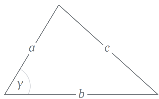
      Match 5: 30 to 34 Win

      Here, we missed the auton pixel and fell victim to the same code bug that happened before, which left us static for all of teleop. We got very lucky as our alliance partner scored their drone and a couple of pixels, carrying us to victory(we scored no points in this match). We thought we had fixed the code bug during testing on the practice field, but we simply didn’t have enough time to verify that.

      Match 6: 37 to 26 Win

      In our final match, our auton remained consistent, but yet again, the code issue reared its ugly head. This meet was very much the tale of two halves. A sort of successful first 3 matches led to us pushing new code and build changes to get features such as the lift working, which eventually

      We'll be posting another post with our post-mortem thoughts, takeaways, deeper analysis, and some plans for the future.

      Positioning Algorithms

      Positioning Algorithms By Jai and Alex

      Task: Determine the robot’s position on the field with little to no error

      With the rigging and the backdrops being introduced as huge obstacles to pathing this year, it’s absolutely crucial that the robot knows exactly where it is on the field. Because we have a Mecanum drivetrain, the included motor encoders slip too much for the fine-tuned pathing that we’d like to do. This year, we use as many sensors (sources of truth) as possible to localize and relocalize the robot.

      Odometry Pods (Deadwheels)

      There are three non-driven (“dead”) omni wheels on the bottom of our robot that serve as our first source of truth for position.

      The parallel wheels serve as our sensors for front-back motion, and their difference in motion is used to calculate our heading. The perpendicular wheel at the center of our robot tells us how far/in what direction we’ve strafed. Because these act just like DC Motor encoders, they’re updated with the bulk updates roughly every loop, making them a good option for quick readings.

      IMU

      The IMU on the Control Hub isn’t subject to field conditions, wheel alignment or minor elevation changes, so we use it to update our heading every two seconds. This helps avoid any serious error buildup in our heading if the dead wheels aren’t positioned properly. The downside to the IMU is that it’s an I2C sensor, and polling I2C sensors adds a full 7ms to every loop, so periodic updates help us balance the value of the heading data coming in and the loop time to keep our robot running smoothly.

      AprilTags

      AprilTags are a new addition to the field this year, but we’ve been using them for years and have built up our own in-house detection and position estimation algorithms. AprilTags are unique in that they convey a coordinate grid in three-dimensional space that the camera can use to calculate its position relative to the tag.

      Distance Sensors

      We also use two REV distance sensors mounted to the back of our chassis. They provide us with a distance to the backdrop, and by using the difference in their values, we can get a pretty good sense of our heading. The challenge with these, however, is that, like the IMU, they’re super taxing on the Control Hub and hurt our loop times significantly, so we’ve had to dynamically enable them only when we’re close enough to the backdrop to get a good reading.

      Meet Our Field Class

      Meet Our Field Class By Jai and Alex

      Task: Explain how we map the field and use it in our code

      A huge focus this season has been navigation; each scoring sequence spans the whole field: from the wing or stacks to the backdrop, and it’s crucial to make this happen as fast as possible to ensure high-scoring games. To do this, the robot needs deep knowledge of all of the components that make up the field.

      Enter: The Field

      Our field class is a 2D coordinate grid that lines up with our RoadRunner navigation coordinates. It’s made up of two types of components: locations & routes. Locations include our Zones, Subzones, and POIs.

      The field's red, blue, and green colors demarcate our overarching Zones. Zones are the highest level of abstraction in our Field class and serve as higher-level flags for changes in robot behavior. Which zone the robot is in determines everything from what each button on the robot does to whether or not it’ll try to switch into autonomous driving during Tele-Op.

      The crosshatched sections are our Subzones. Subzones serve as more concrete triggers for robot behaviors. For example, during autonomous navigation, our intake system automatically activates in the Wing Subzone and our drivetrain’s turning is severely dampened in the backdrop Subzone.

      The circles in the diagram are our POIs. POIs are single points on the field that serve mainly as navigation targets; our robot is told to go to these locations, and the navigation method “succeeds” when it’s within a radius of one of those POIs. A good example of this occurs in our autonomous endgame: the circle in front of the rigging serves as the first navigation target for hang and the robot suspends itself on the rigging at the lower circle.

      A combination of Zones, Subzones, and POIs play into our automation of every game, and our field class is crucial to our goal of automating the whole game.

      League Meet 3 Play-By-Play

      League Meet 3 Play-By-Play By Anuhya, Krish, Jai, Sol, Tanvi, Alex, Vance, and Georgia

      Task: Review our performance at our 3rd League Meet

      Today, Iron Reign had its third league meet. It was more successful than our last league meet, with more success with both the drone launcher and our autonomous code. Overall, we went 5-1 and ended up ranked 3rd due to our relatively high tie-breaker points. We ended up perfectly tying with the 2nd place team when it came to autonomous points, and we had a lower score than them for end-game. We saw huge improvements in driving from our previous league meets to this league meet, and learned many valuable lessons about being prepared for matches. However, before we look at some of our takeaways, here’s a brief play-by-play of our matches.

      Match 1: 77 - 23 Win

      We scored a 45 point auton this round, which is the highest we can score alone. We placed a purple pixel where it was supposed to go, but a bug that started happening with our auton so it could detect placement is that it starts spinning. This can lead to an issue because of how short the autonomous period is, but it wasn’t an issue here. We placed the yellow pixel on its appropriate location on the backdrop and then parked. Driving during the Tele-Op portion started out rocky and we hit the rigging a few times. We were also having issues working together with our alliance partner, as they ended up in front of the backdrop many times as we tried to score and they would be in the wings at the position we needed to be in. One of our wheels was also stuck in a pixel for the majority of the match, which is a problem that could easily have been avoided if we had side shields on the robot. Our alliance team got hung, resulting in our win.

      Match 2: 88 - 102 Loss

      We got a 28 point auton, where we placed the purple pixel correctly but the yellow pixel was on the wrong section of the backdrop. We also got parking. Our partner was a push bot but they could get the drone as well. We ended up getting a total of 6 pixels on the backdrop by the end of Tele-Op, and we got hang but couldn’t get the drone launched because the drone hit the rigging. Our opponent launched their drone, resulting in their win.

      Match 3: 106 - 31 Win

      Once again, we got a 28 point auton, where we placed the purple pixel correctly but the yellow pixel was on the wrong section of the backdrop. We also got parking. In this match, none of the other robots had an auton. During Tele-Op, we got a mosaic by placing an additional purple and green pixel. With the help of our alliance partner, Iron Core, we got 6 total pixels on the backdrop by the end of Tele-Op. By the end game, our drone had already fallen off, which was a great missed opportunity for points which remained throughout this entire league meet. The Skyhooks weren’t set up prior to the match, so they were already locked and we couldn’t hang. This showed us how much we need to have a pre-match checklist. We also got 30 points in penalties.

      Match 4: 67 - 17 Win

      We got a 6 point auton. The purple pixel missed the tape and the yellow pixel fell before it could reach the backdrop. We got parking, however. In Tele-Op, we knocked over the pixel stack so our alliance partner could pick up pixels from the ground. We scored a purple and green pixel in addition to a yellow pixel, resulting in a mosaic. The stage door broke as we went through the center because it was already bent and our robot hit the lowest part, resulting in it bending even further. While we were taking in new pixels, we dropped the drone. At the end of tTele-Op, we had a total of 4 pixels on the backdrop. In the end game, we hung but because our drone dislodged, we couldn’t score the drone. Our alliance partner got parking.

      Match 5: 112 - 29 Win

      We got a 26 point auton because we scored the purple pixel properly, but the robot dropped the yellow pixel because of the “spin sequence”, which ensures that we are pointing directly at the backdrop but takes too much time. We also got parking. In the Tele-Op portion, we hit the stage door but it didn’t mess us up too badly. Some traffic by the wings also slowed us down. We almost got a mosaic but there was a very small gap between two of the pixels, and all the pixels have to be perfectly touching to be a mosaic. We failed to try for a second mosaic even though there was time. We scored a total of 7 pixels on the backdrop, 1 on the backstage. In the end game, we scored the drone to get a full 30 points and we hung as well! This was our most successful drone launch of the league meet!

      Match 6: 85 - 34 Win

      We got a 25 point auton, with the purple pixel barely touching the tape. The robot did the “spin sequence” again, but timed out completely so the yellow pixel wasn’t dropped at all. We also got parking. In Tele-Op, we first scored the yellow pixel we couldn’t score because of the weird auton. One of our alliance partners also knocked one of our pixels off the backdrop. Placing one of the pixels resulted in a ricochet so we couldn’t score a mosaic. We had a total of 6 pixels on the backdrop by the end of teleop. In end game, we couldn't score a drone because the drone launcher wasn’t tensioned. This was the second match where we noticed this issue.

      We'll be posting another post with our post-mortem thoughts, takeaways, deeper analysis, and some plans for the future.

      Applying Forward/Inverse Kinematics to Score with PPE

      Applying Forward/Inverse Kinematics to Score with PPE By Elias and Alex

      Task: Explain how we use kinematics to manipulate PixeLeviosa (our Outtake)

      This year’s challenge led Iron Reign down a complex process of developing an efficient means of scoring, which involved the interaction between the intake and outtake. Currently, we are in the process of implementing Forward and Inverse Kinematics to find and alter the orientation of our outtake, known as PixeLeviosa.

      Forward and Inverse kinematics both revolve around the part of a robot’s subsystem, known as the end-effector, which is essentially what the robot uses to score or achieve certain tasks (that being PPE’s scoopagon). The simple difference between forward and inverse kinematics is that forward is the method of find the end-effector’s position given the angles of each respective joint and using geometric principles to find its position from there, whereas inverse kinematics has you finding the angles of each joint given the position of the end-effector. Typically, one will use the methods and formulas derived from forward kinematics to then apply them for inverse kinematics.

      For PPE, we use inverse kinematics to set PixeLeviosa’s orientation given a point in relation to the backdrop such that the outtake maneuvers itself for effective scoring and reducing cycle times. We hope to have this fully fleshed out by State!