24 Nov 2024
Post 6
Awards: journal and think
League Meet 1 Post-Mortem
By Ren, Aarav, Nalin, Fernando, Jai, Krish, Sol, and Georgia
Task: Analyze our League Meet 1 Performance
After every competition, the team sits down and runs a SWOT(Strengths, Weaknesses, Opportunities, Threats) analysis on the robot and its performance. Here is a breakdown of everything we learned using the SWOT technique after League Meet 1.
Strengths:
One of the biggest strengths that our robot has was auton reliability. In every single match we played, the auton always worked. Having this reliability allowed us to have a strong foundation and build off of this base auton in a more efficient manner. Another strength we possessed was good time management. The team was not late to complete any of the inspections, and we were always on the queueing table on time. The team was organized allowing us to run smoothly.
Weaknesses:
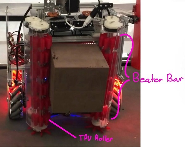
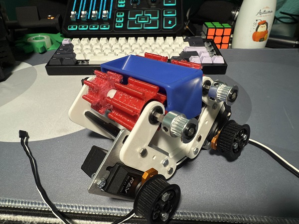
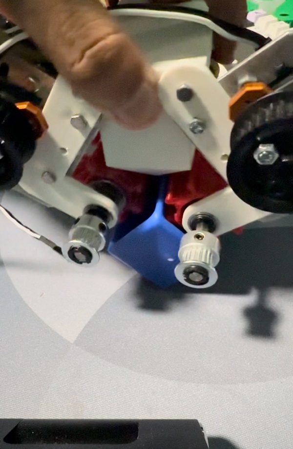
There was a missed opportunity on the code part since we were never scoring in the high basket in TeleOp or auton. If the build team had finished a little bit earlier, the code team would have been able to code the robot to score samples in the high basket. Scoring in the low baskets made auton almost pointless even if it was reliable. Specifically in the beater bar, the window for the color sensor was not optimal. This made tuning inconsistent, and the problem was very obvious when it came to yellow samples since the belt stopped much later than it would have for red or blue samples. Overall, the belt of the beater bar was also much slower than we wanted since the belt was small.
Opportunities:
We want to better segment the time before competitions to make sure the build, code, and drive team all receive almost the same amount of time with the robot. Allocating time in this manner will allow the drive and code team to have an adequate amount of time to make sure other things are not lacking such as fine tuning in the code or not enough practice time driving. We want to practice driving under competition conditions to gain the most accurate data. We want to increase the speed of the belt and try to hang on the low bar with a new arm.
Threats:
The biggest threat to the team was a lack of coding time. If the code team received more time we could have scored the high basket. Scoring on the high basket would have let us receive almost double the points than we were actually scoring. Another major threat was not giving the drive team enough time with the robot. We would have won our last match if we gave the drive team more time since they would be able to figure out how to touch the low bar during endgame.
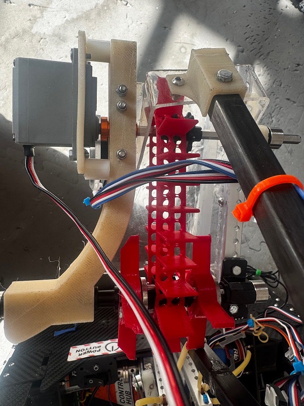
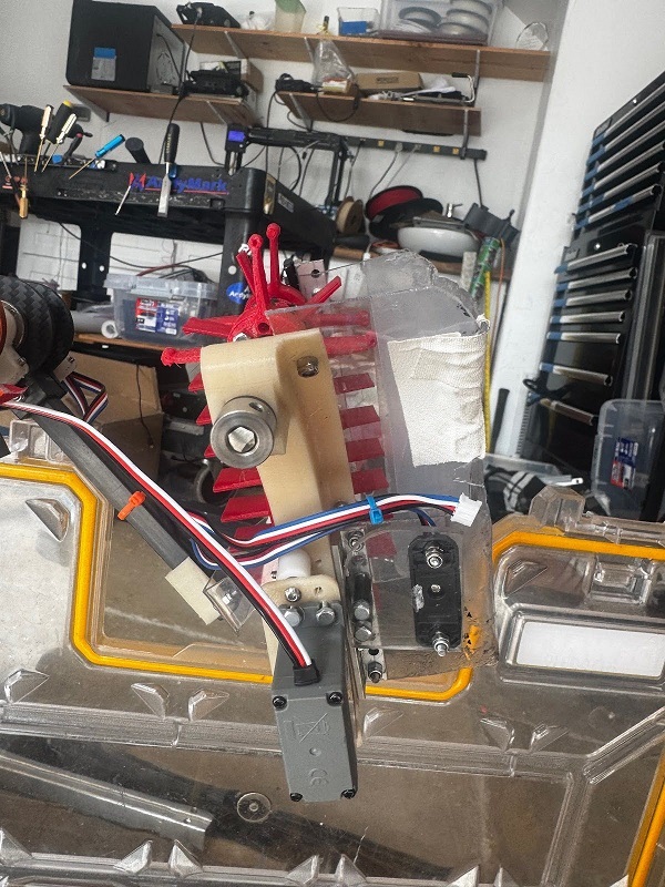
For the second meet, we want to make the following changes: We want to have two separate linear slides, a worm gear shoulder, be able to achieve 2nd level ascension, getting rid of the bridge, and continue to plan a new swerve chassis.
The SWOT analysis gave the team insight on what went well and what needed improvement. This feedback will allow us to have a base plan to follow for meet two. Ultimately, performing a SWOT analysis gives us very valuable and important information to help us develop the robot and the team.