An Overview of the R2V2 Braking System
By Aarav, Tanvi, Krish, Sol, and Gabriel
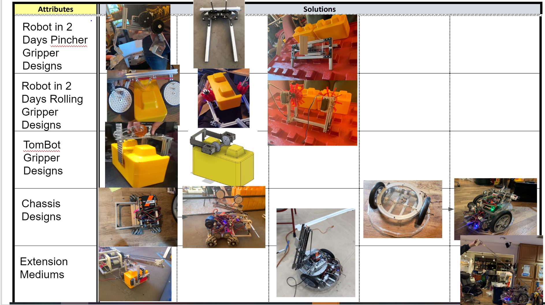
Task: Design a subsystem to control the braking of R2V2
An essential part of effectively remote controlling R2V2 is the developing a method for controlling the brake autonomously. We decided, for safety reasons, to not involve the accelerator at all, so the movement of RV2V would be reliant on the application of pressure on the brake.
Our main requirement with the system's integration with R2V2 was a quick installation process and no permanent changes, meaning that the entire assembly would have to be removable but also rigidly installed for reliability. Additionally, for safety purposes, the resting state of the mechanism would need to be with the brake pushed down, and with power, the brake would be released and the vehicle would move forward. For more information about the safety protocols implemented to protect us, check out this blog post.
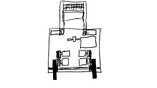
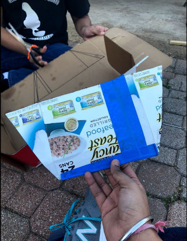
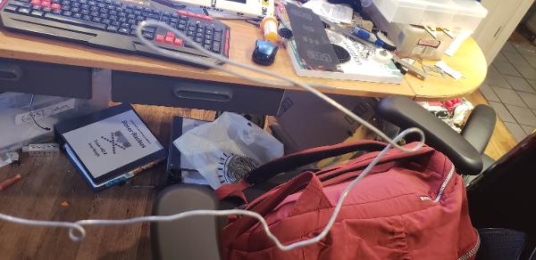
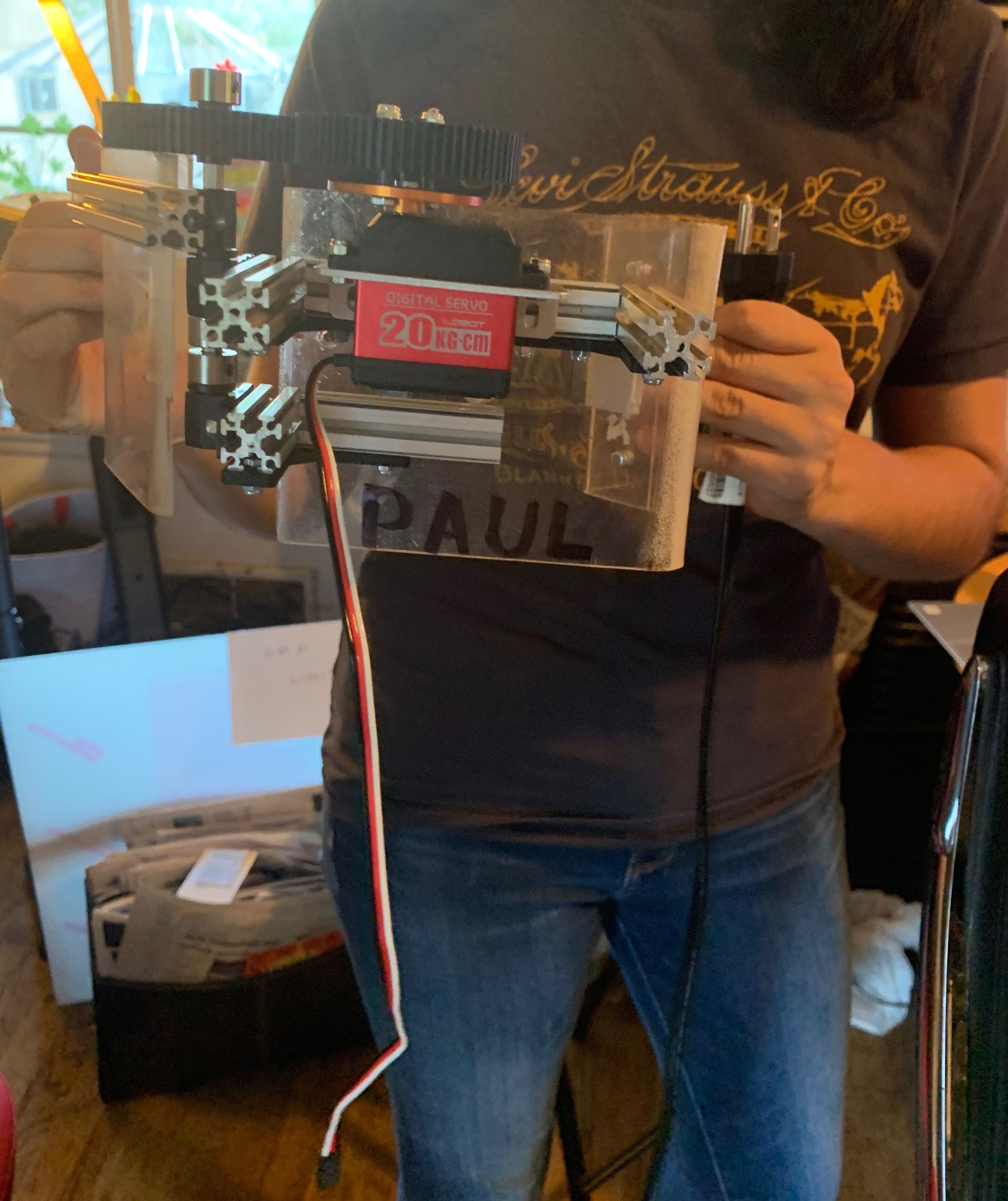
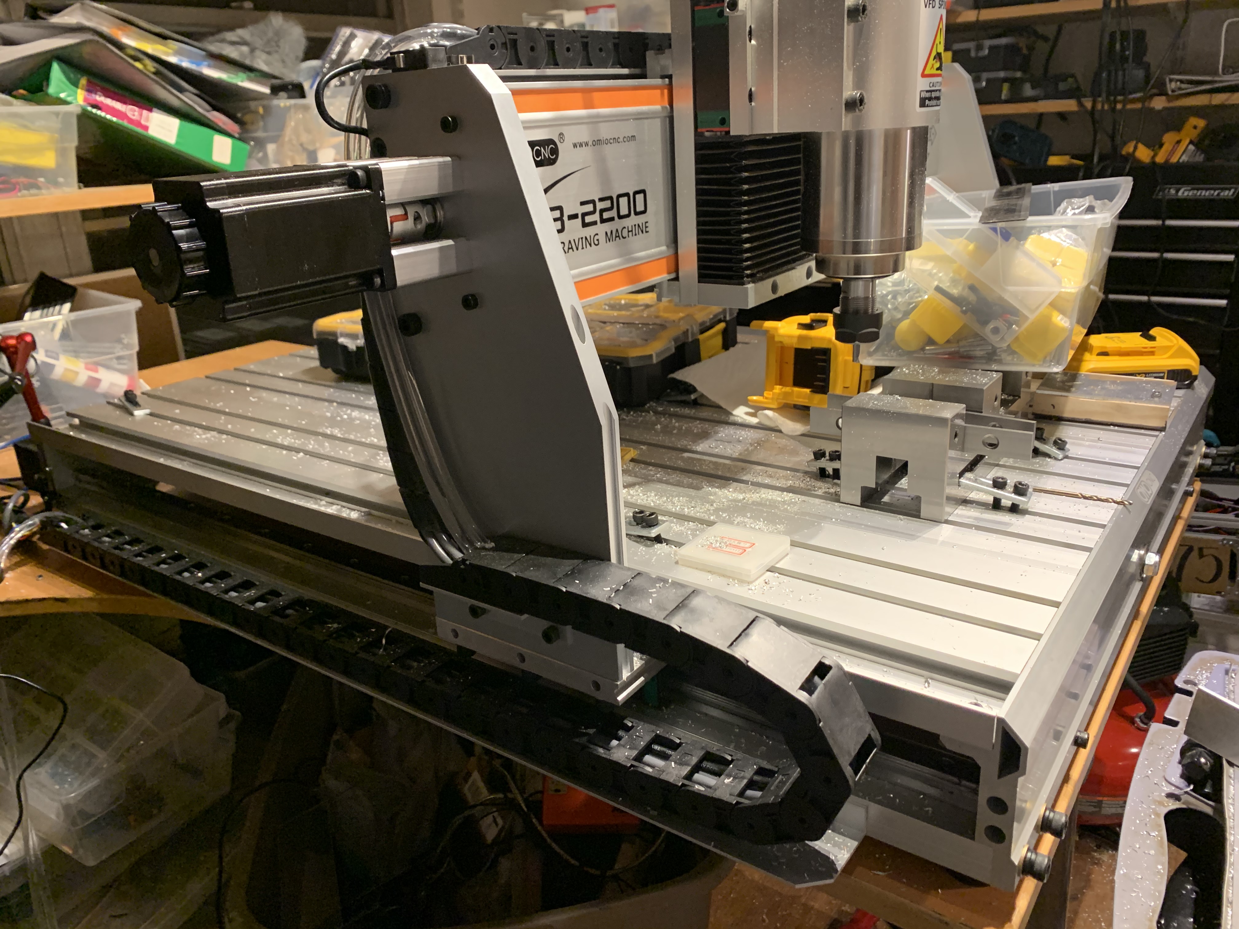
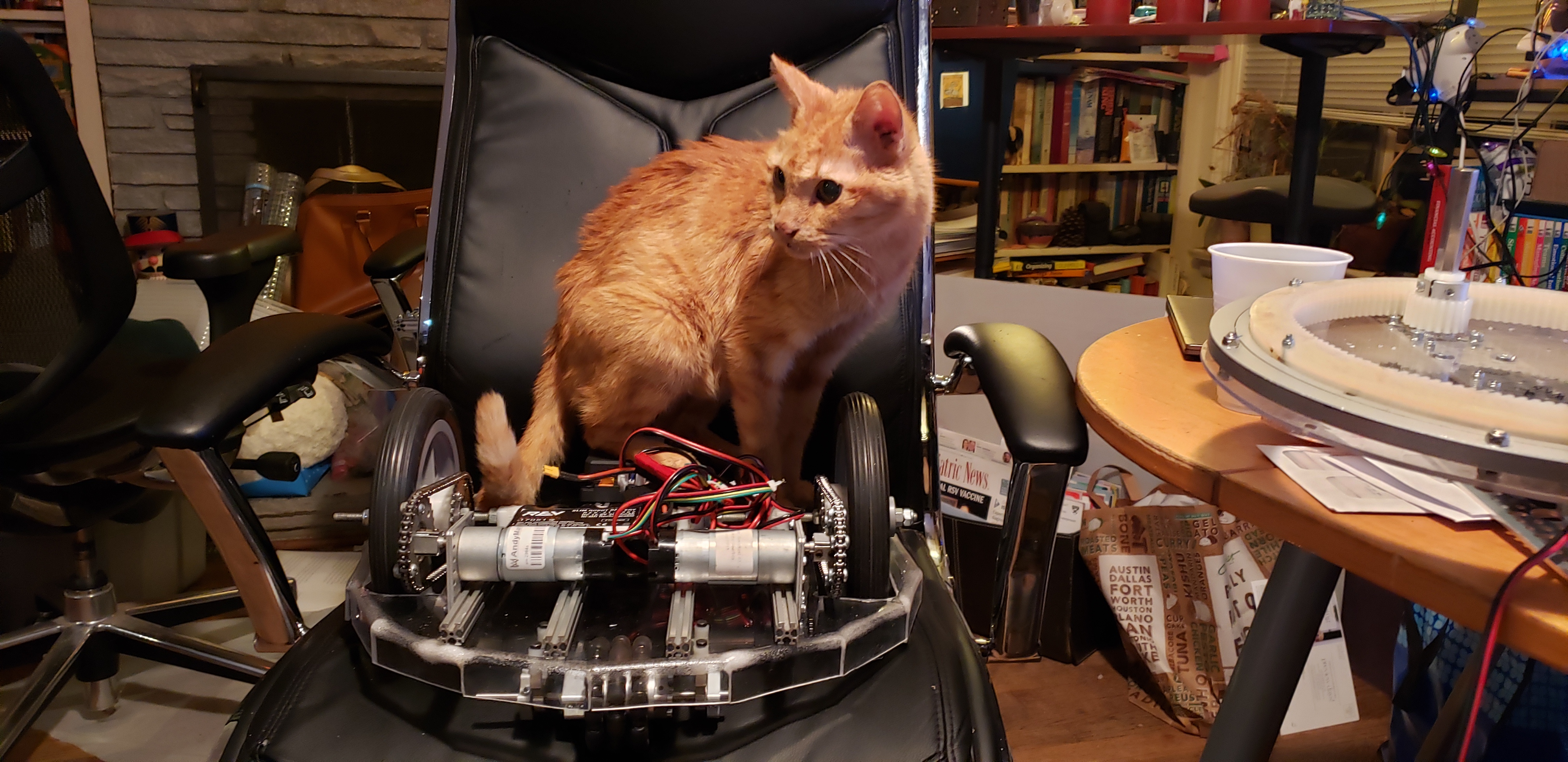
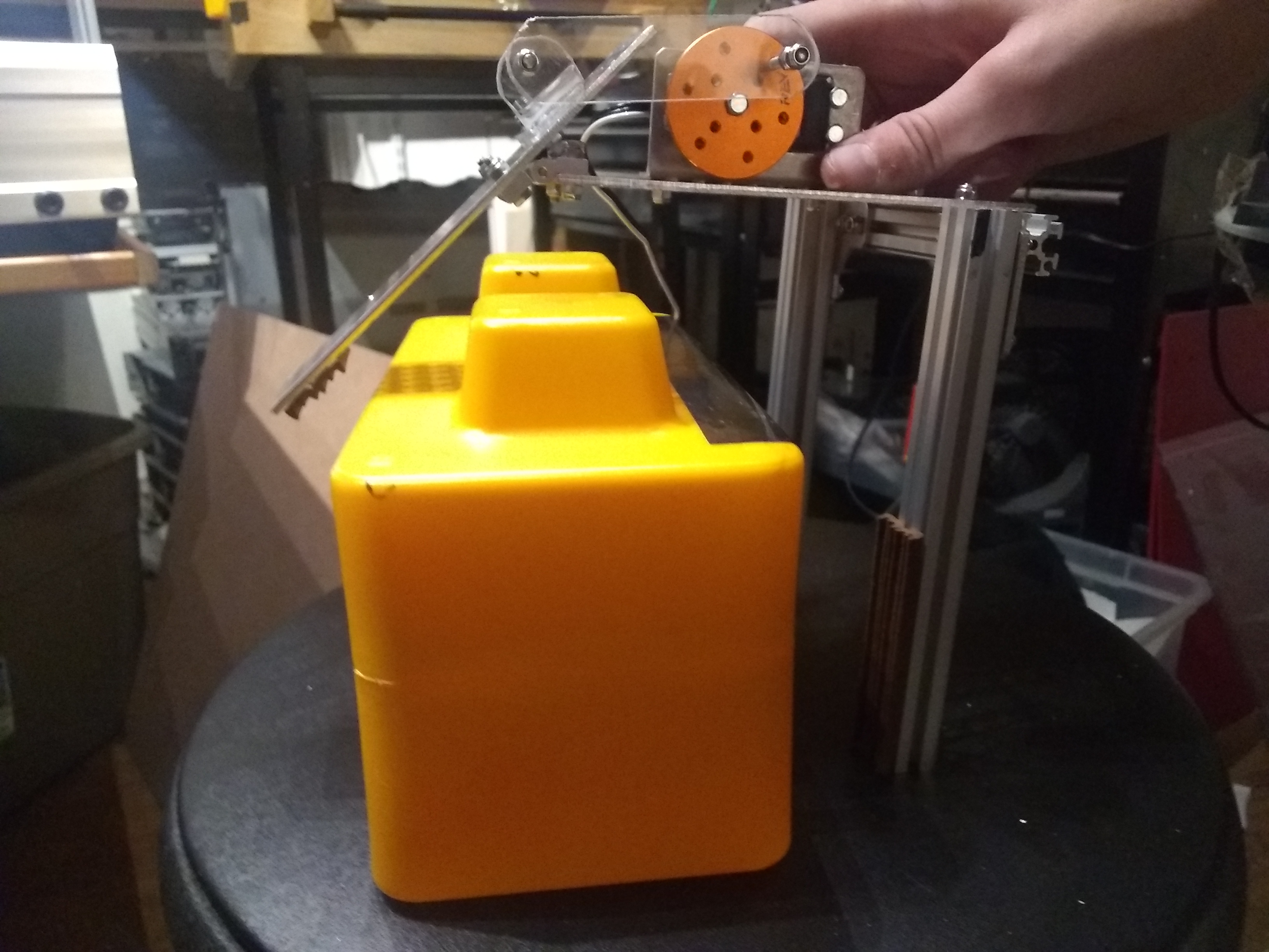
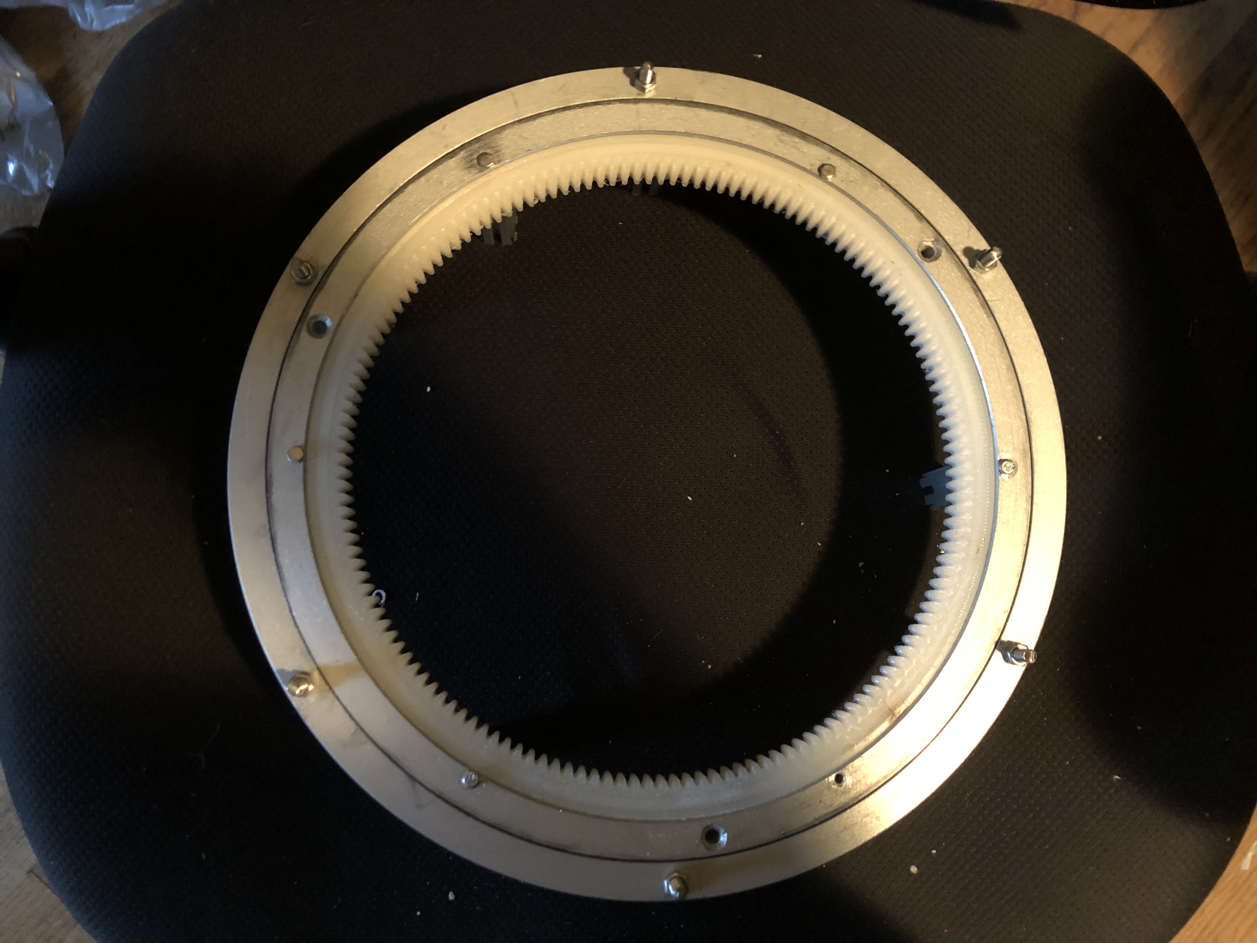
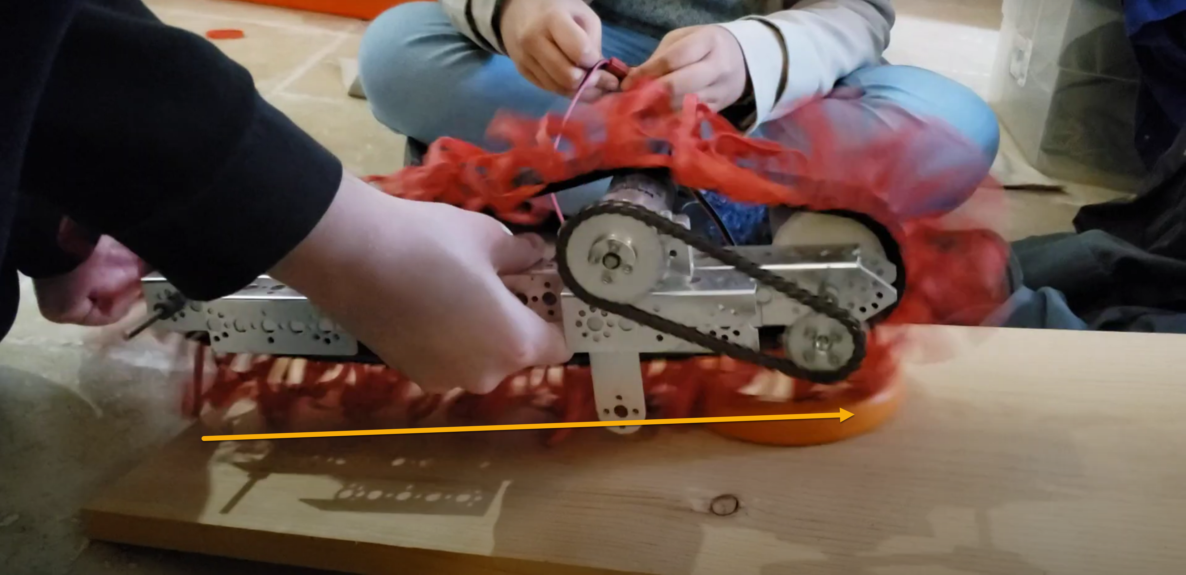
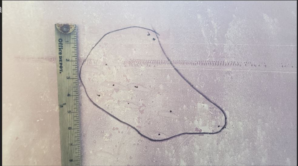
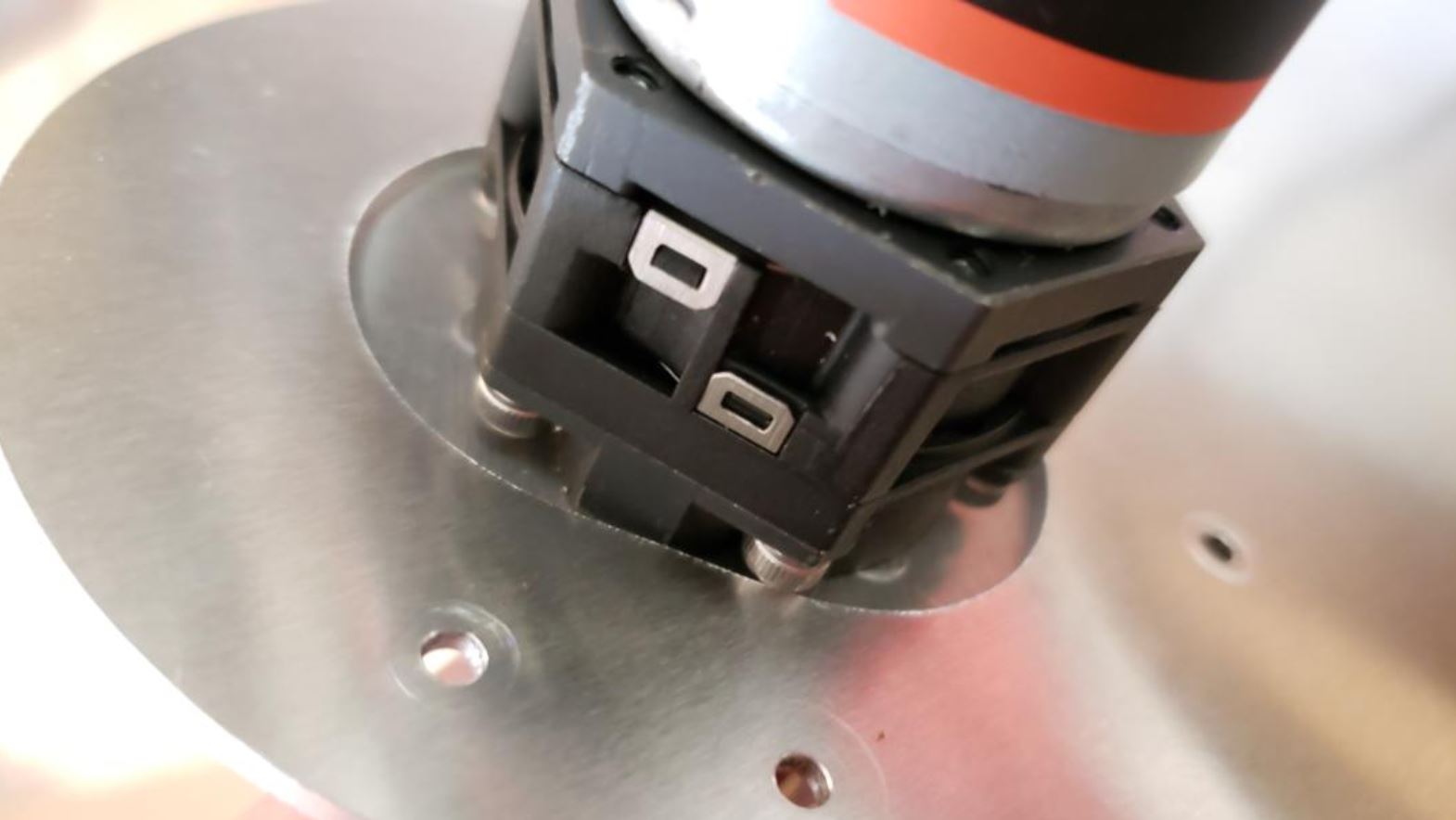
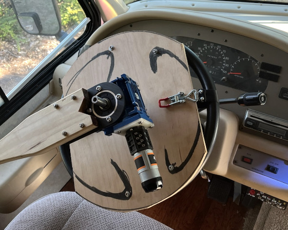
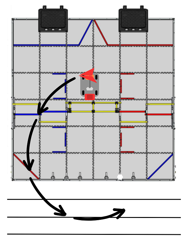
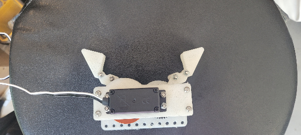
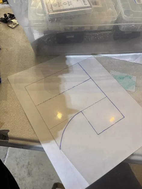
Here is an image of the brake pedal(the larger one) and the area immediately around it. There were size restrictions due to a large center console on the right and the driver’s seat assembly.
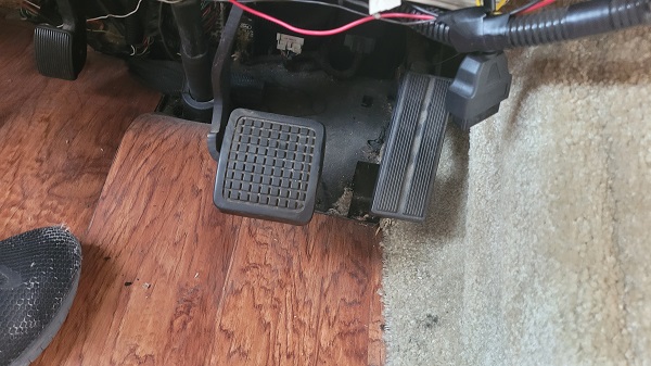
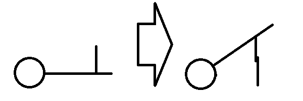
Our initial idea was to use a series of pulleys and bungees to manipulate the brake pedal; however, this applications would require the use of the driver’s seat itself, making us unable to have a driver physically present in the case of emergency. For safety reasons, we pivoted and decided to attempt to emulate the natural movement of a foot and ankle that a human uses to driver.
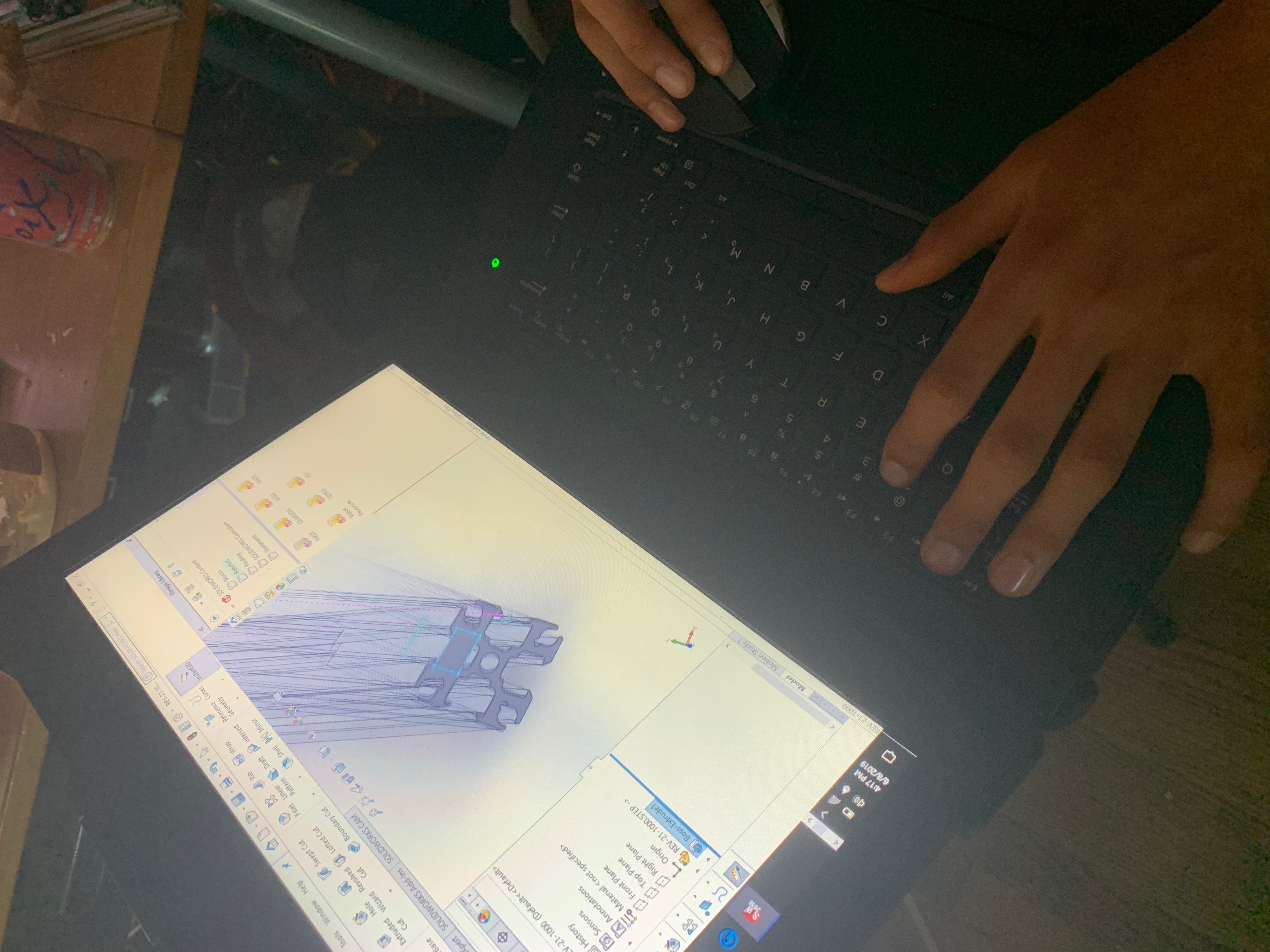
Engineering
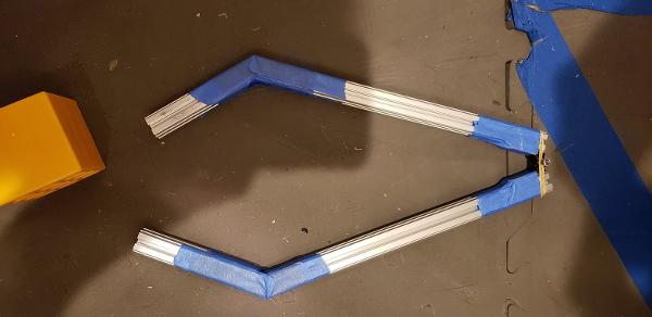
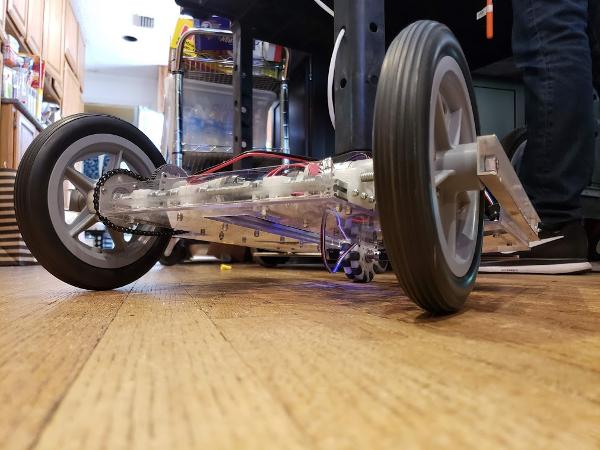
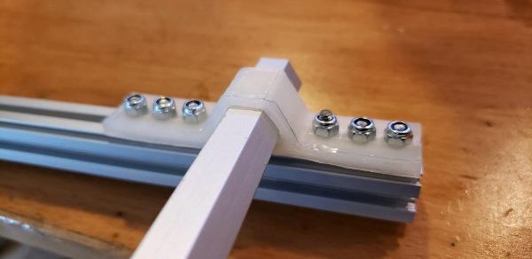
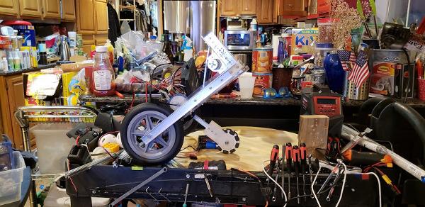
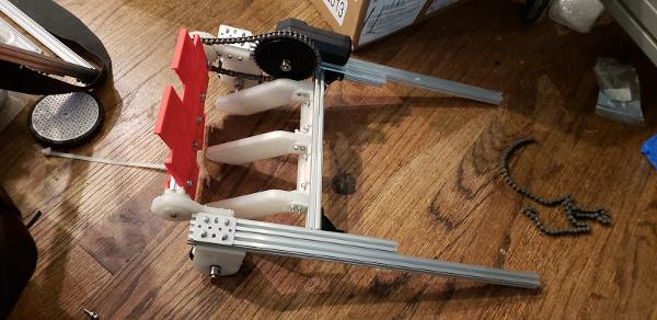
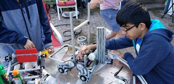
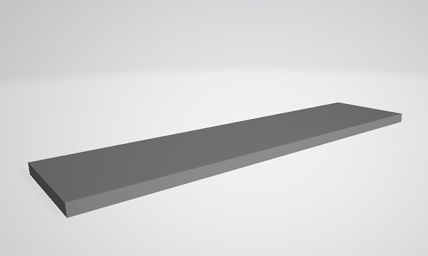
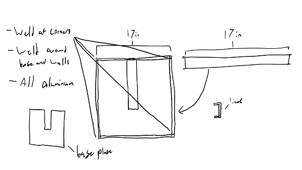
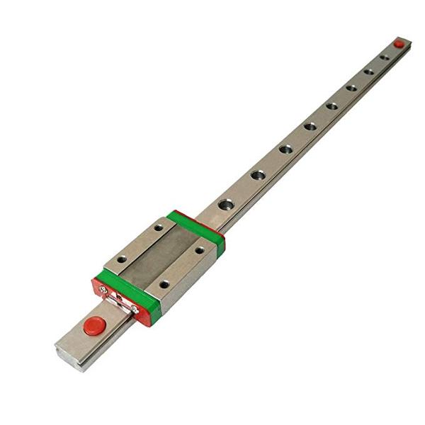
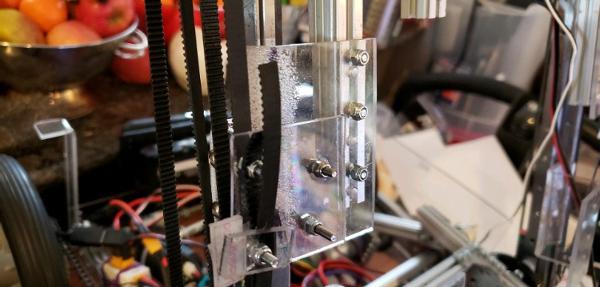
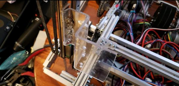
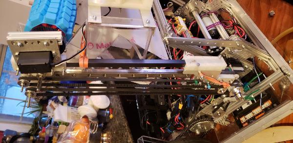
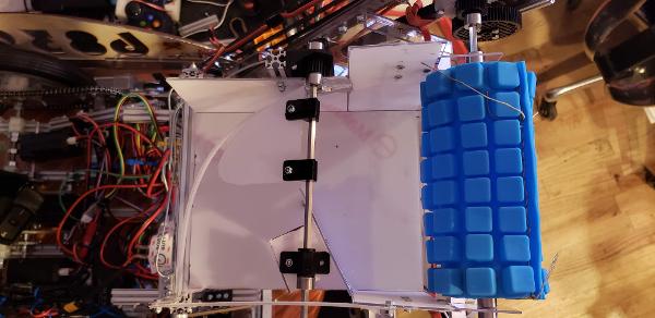
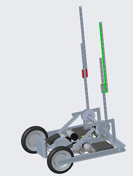
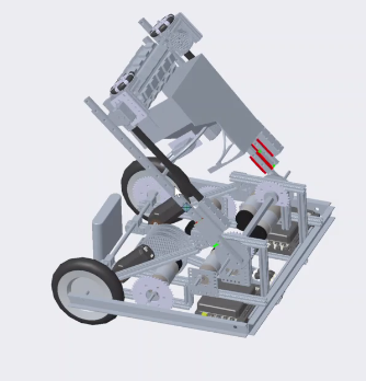
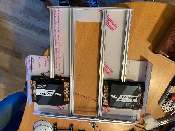
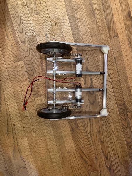
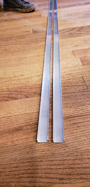
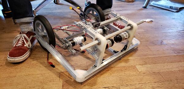
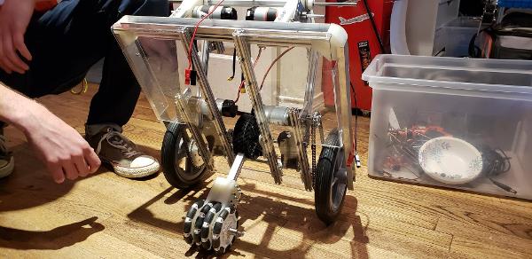
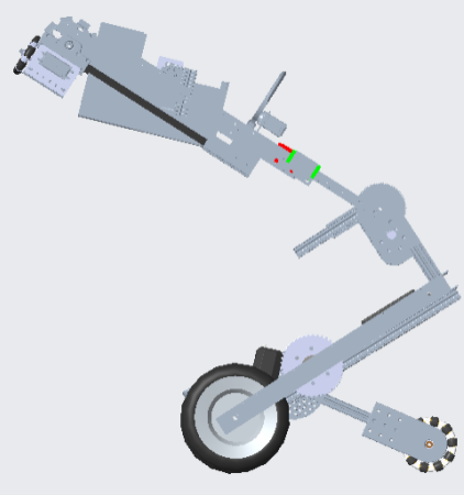
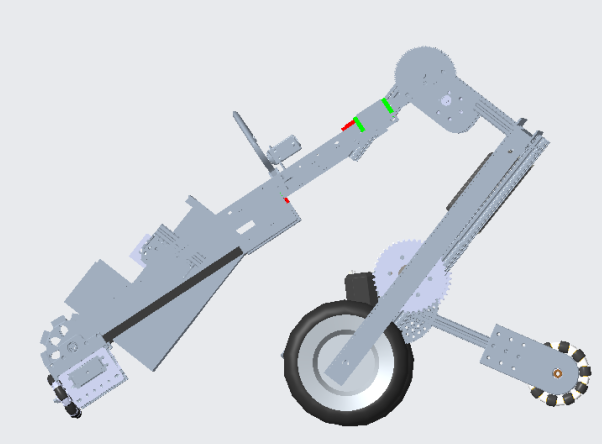
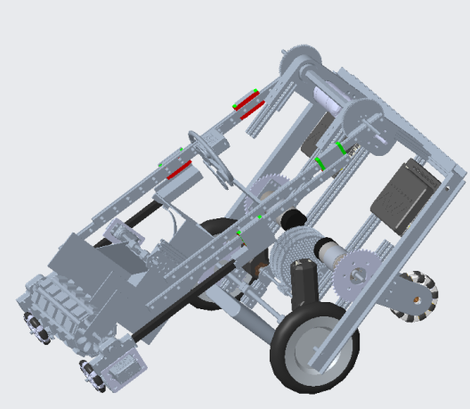
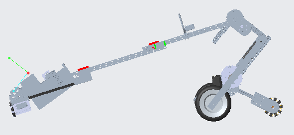
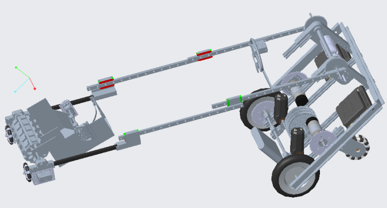
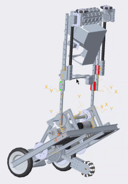
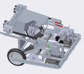
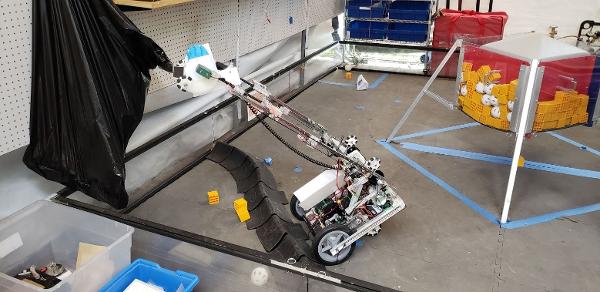
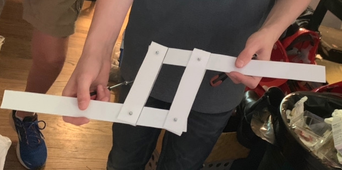
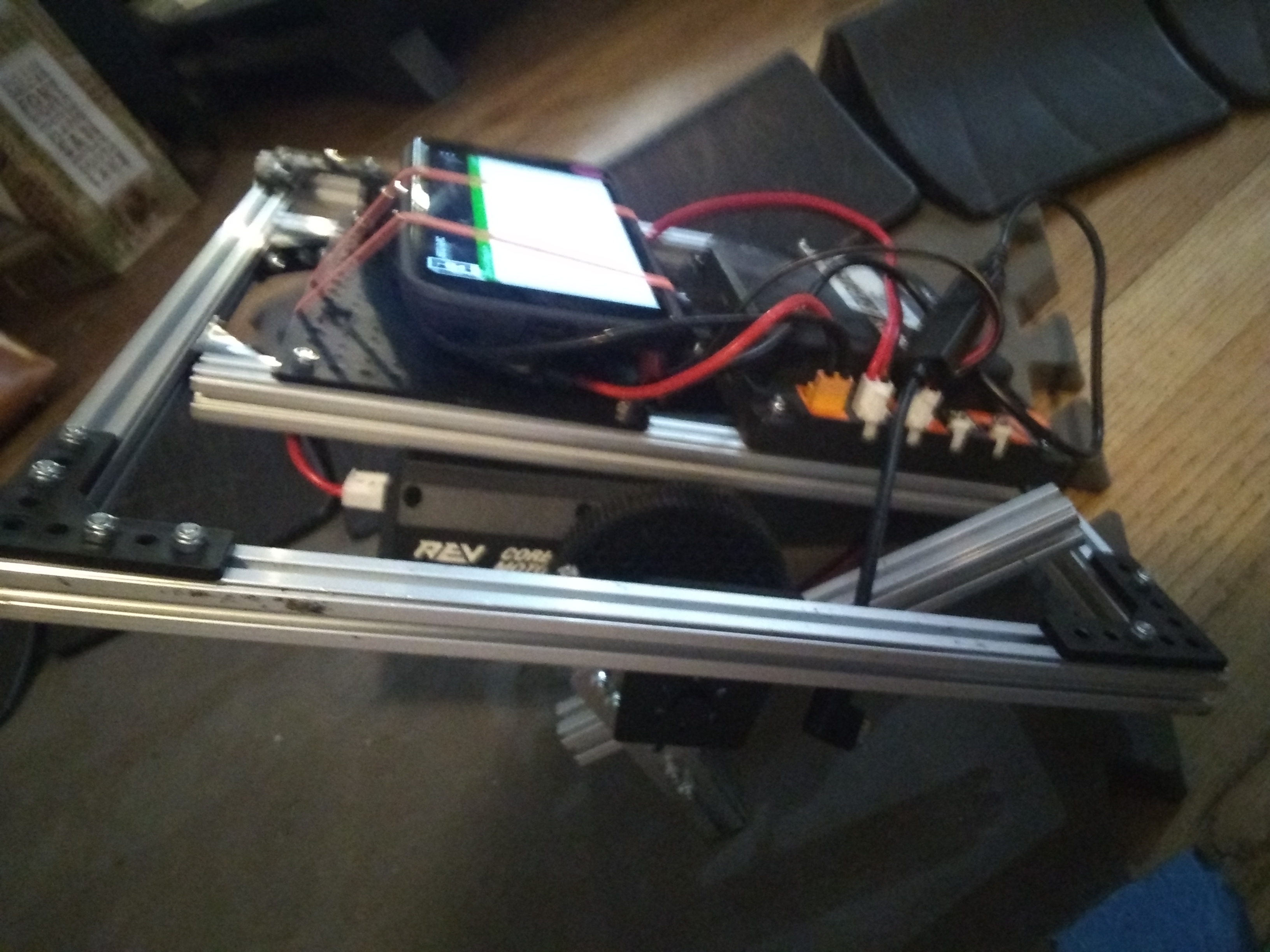
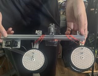
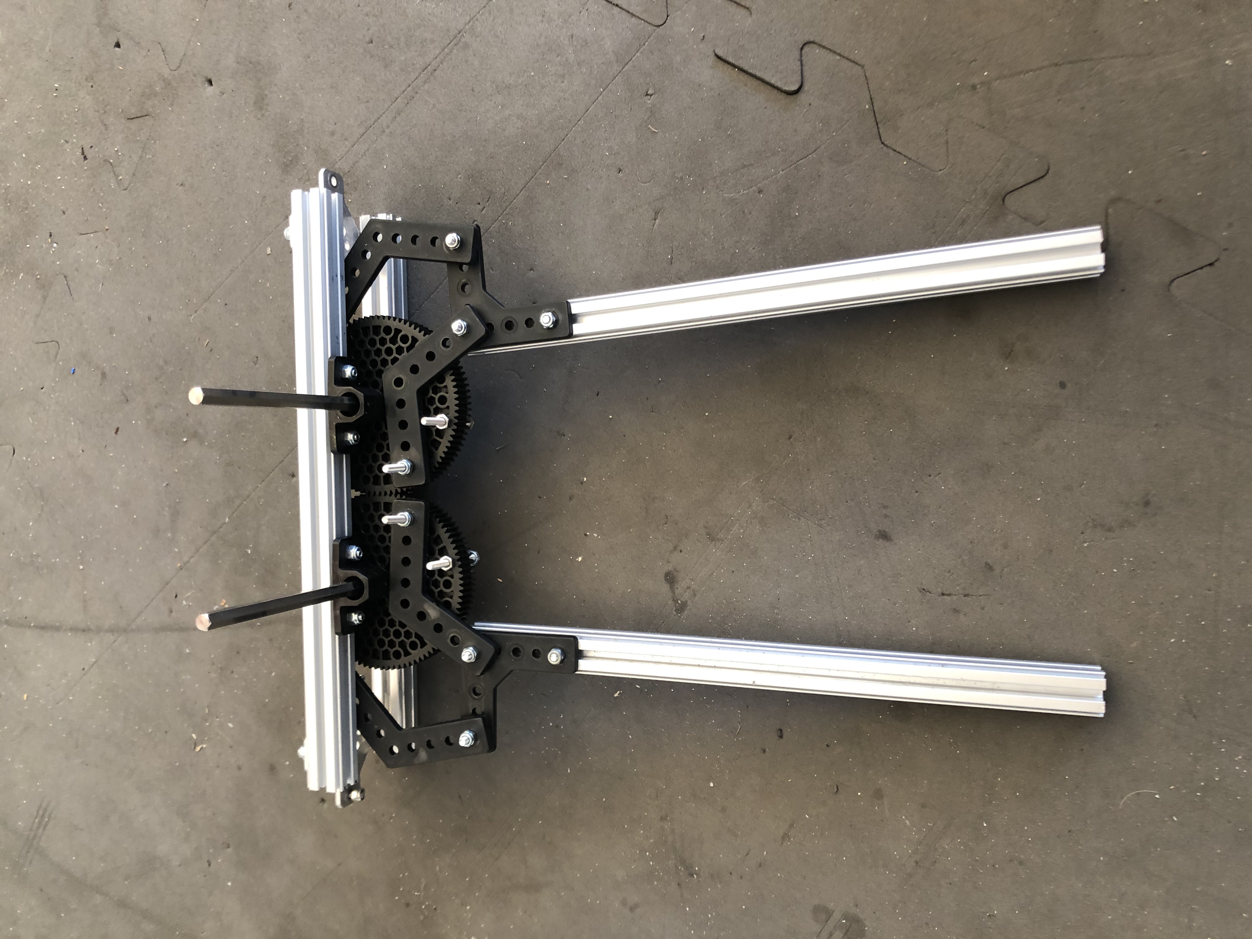
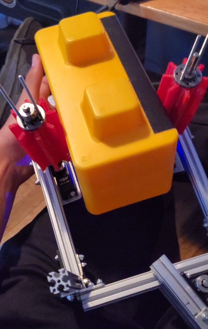
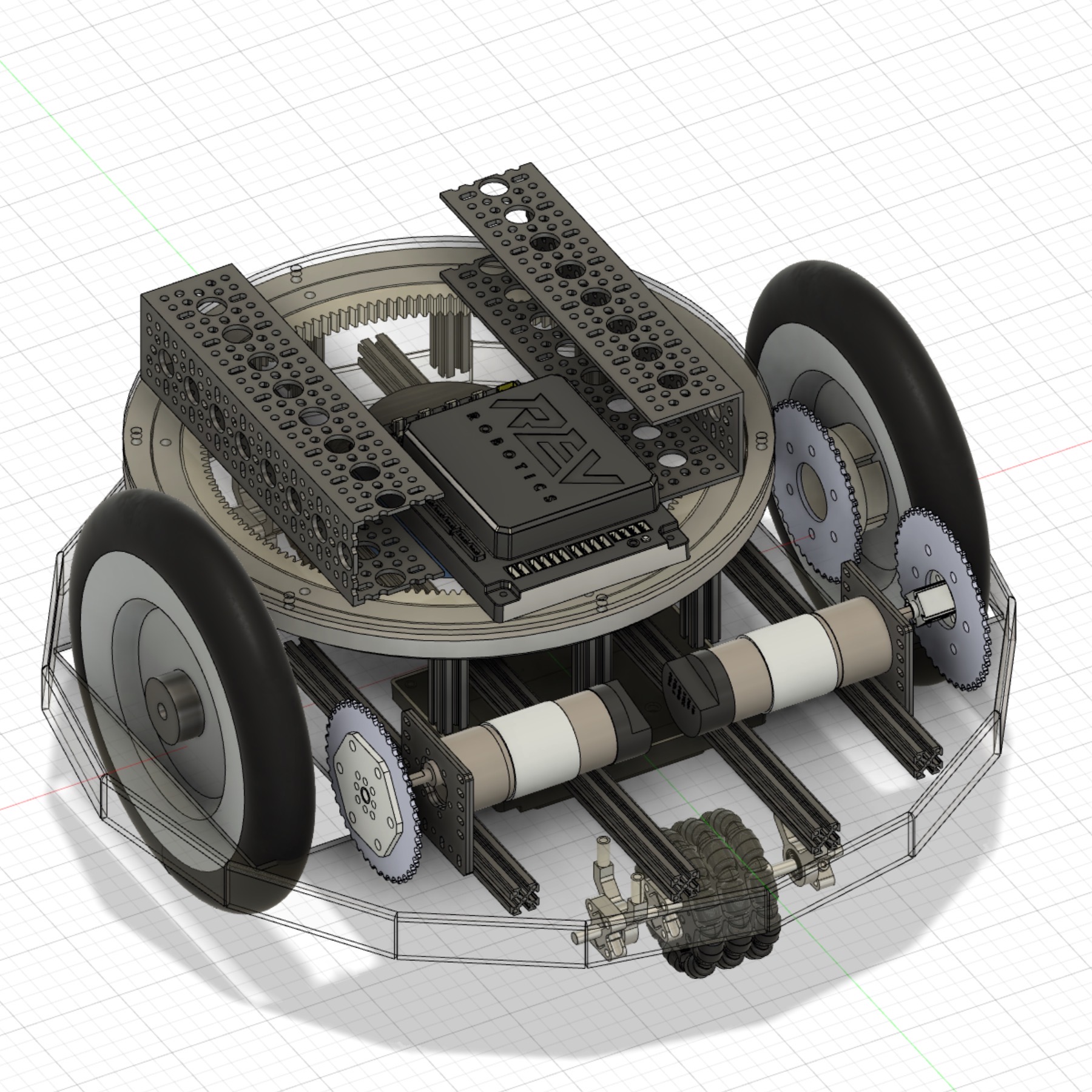
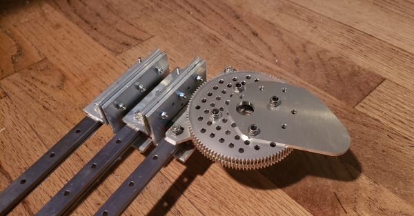
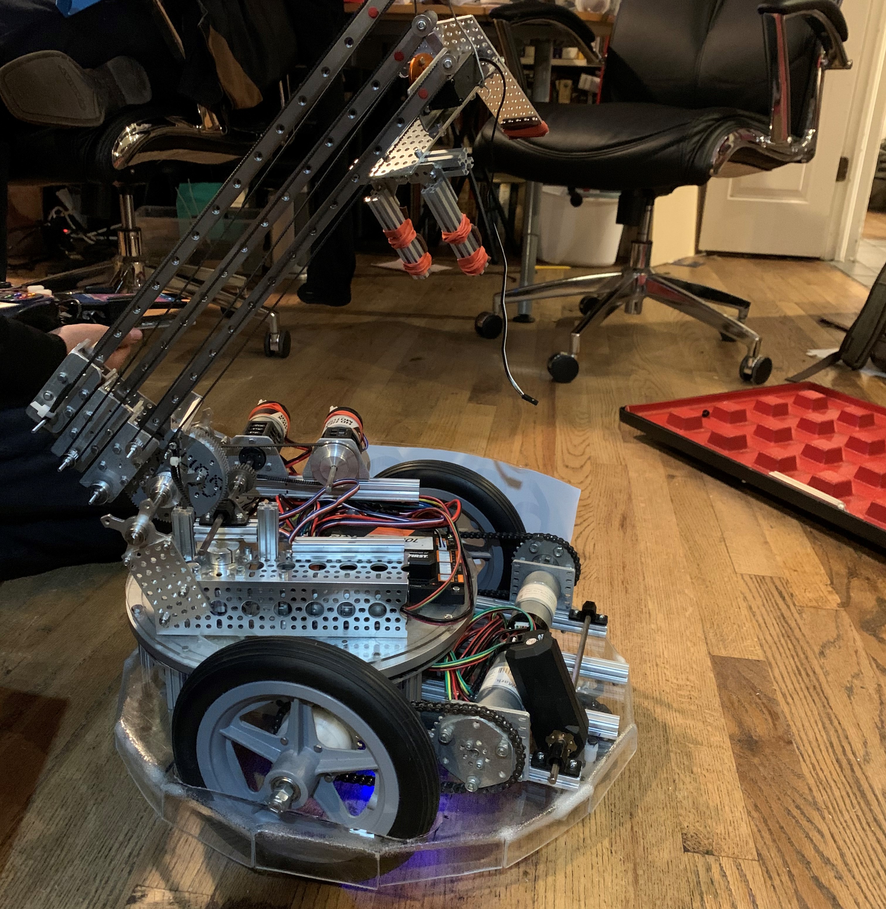
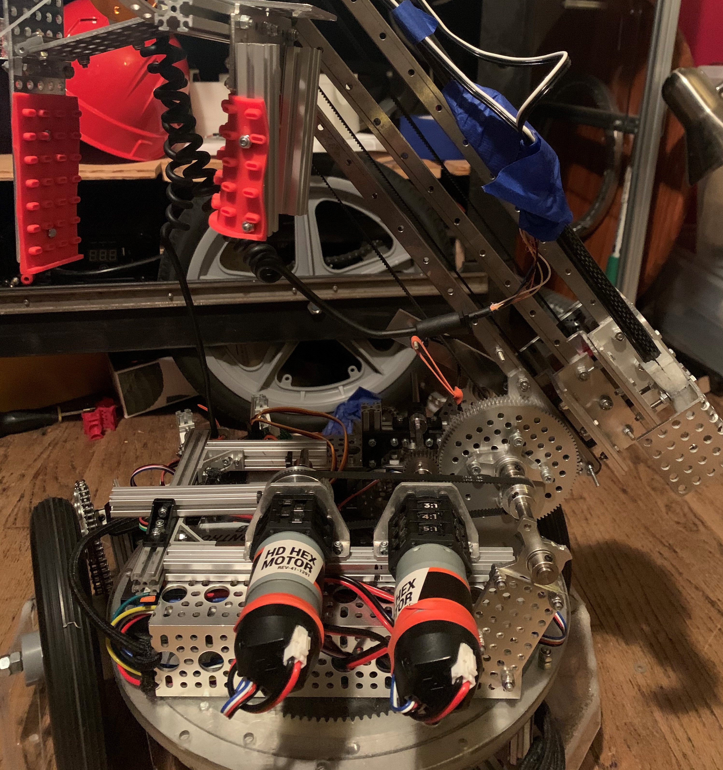
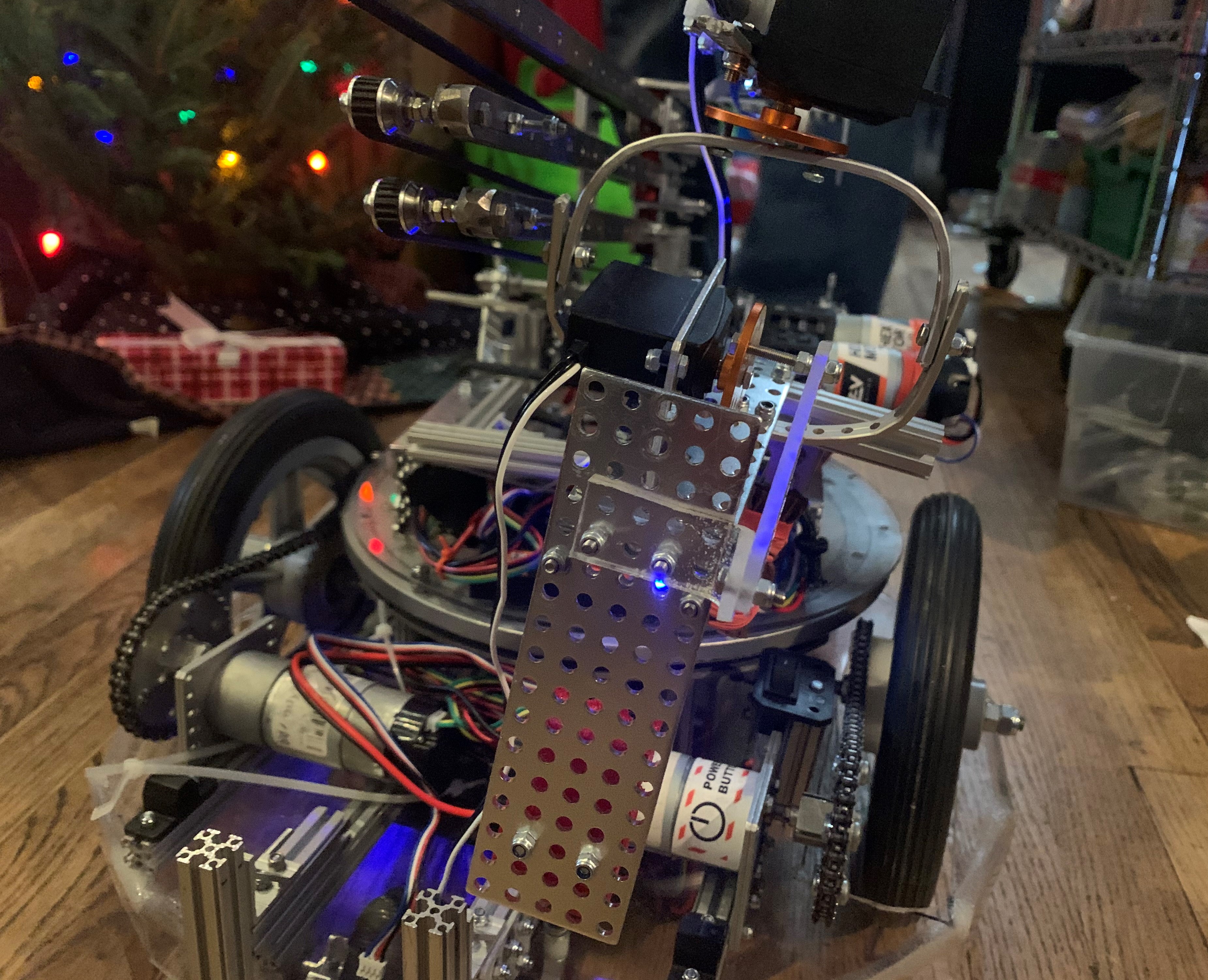
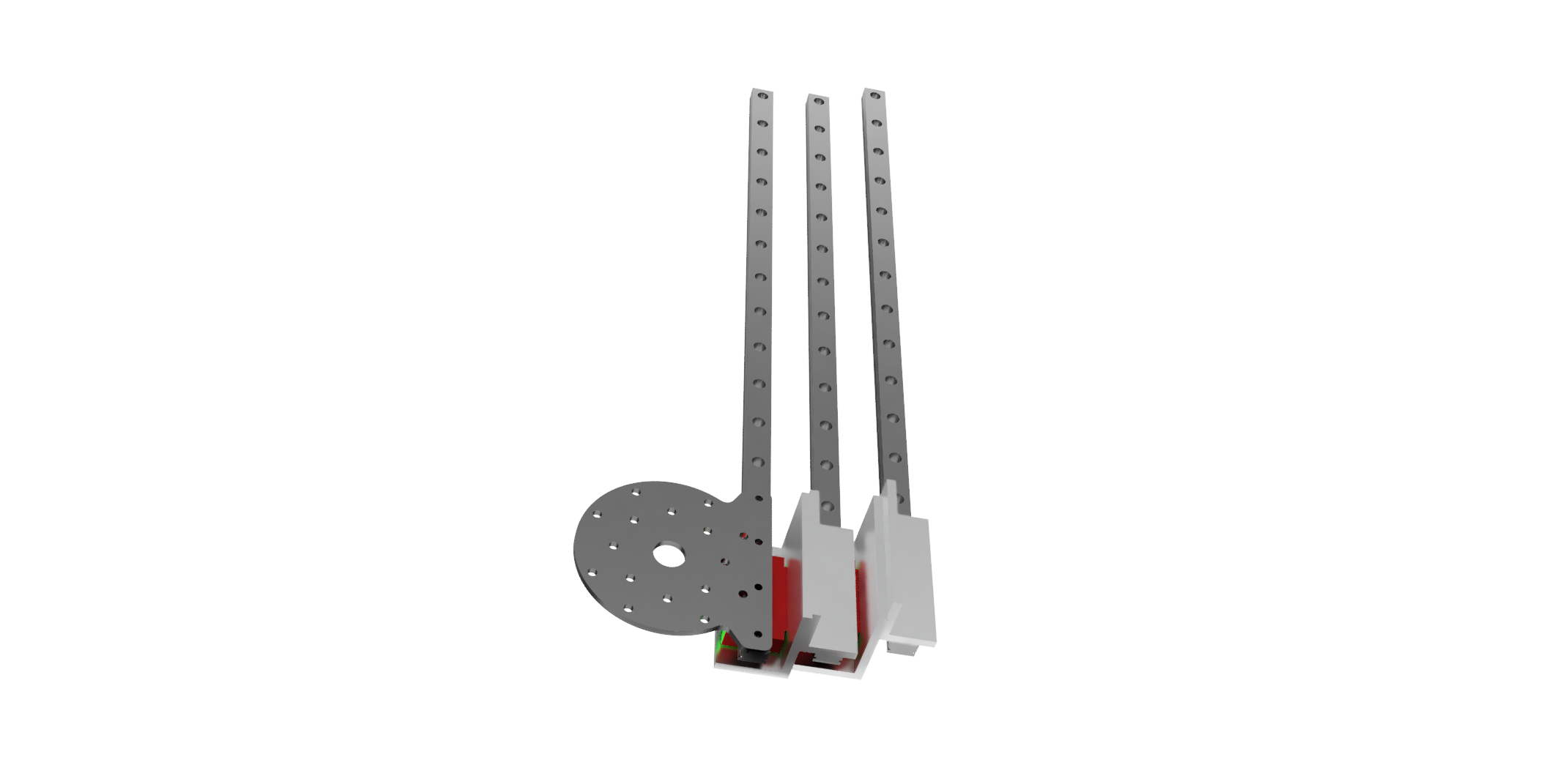
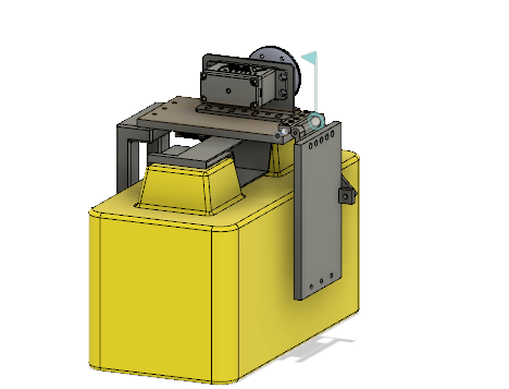
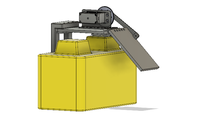
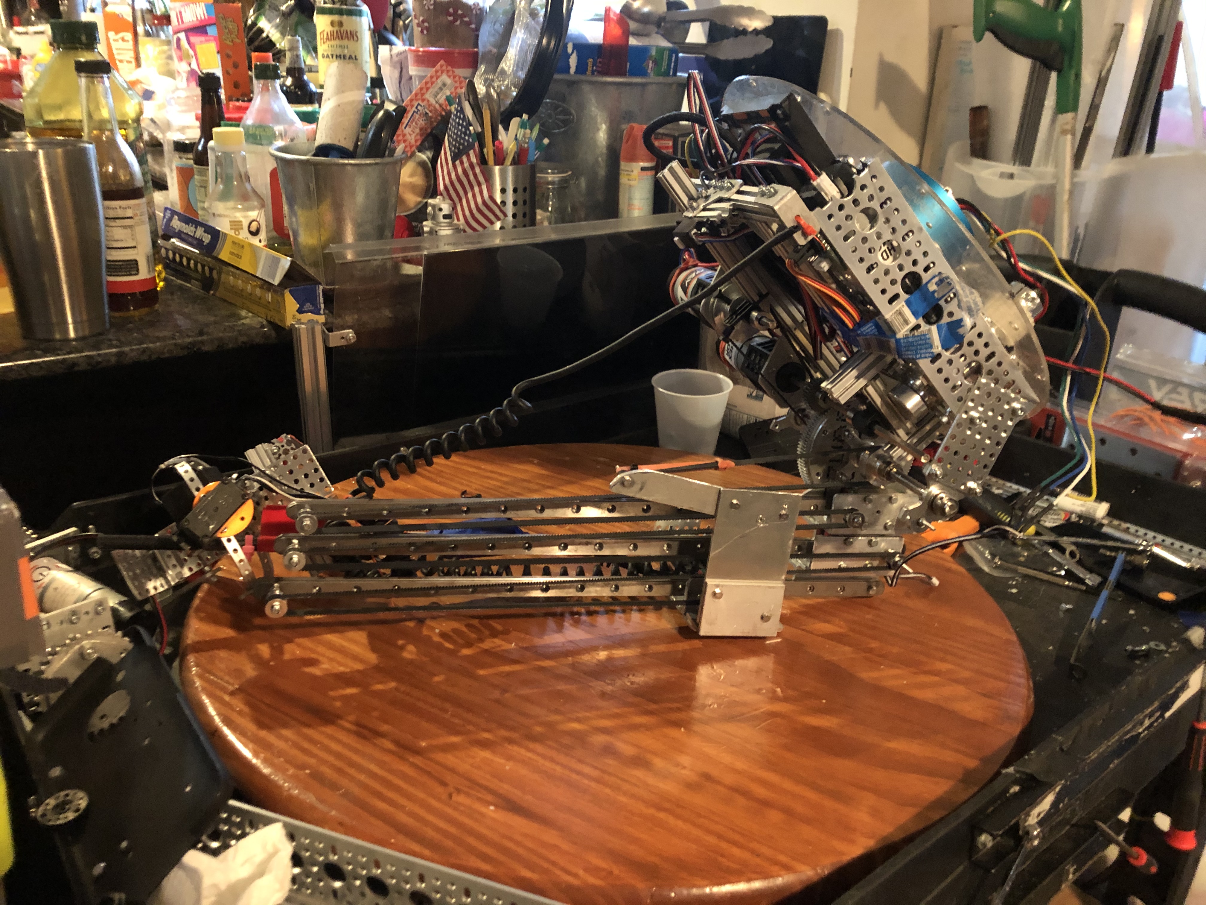
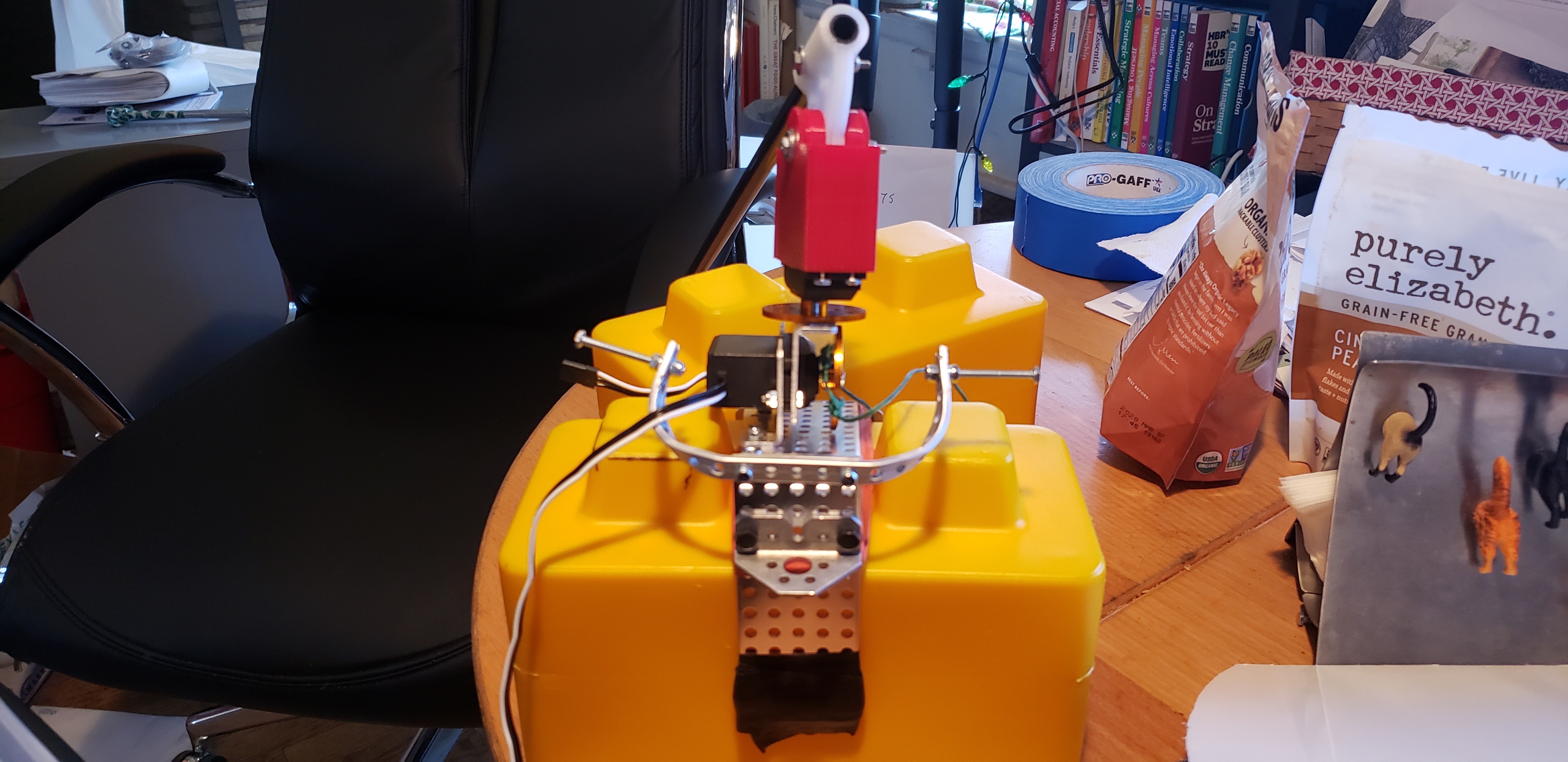
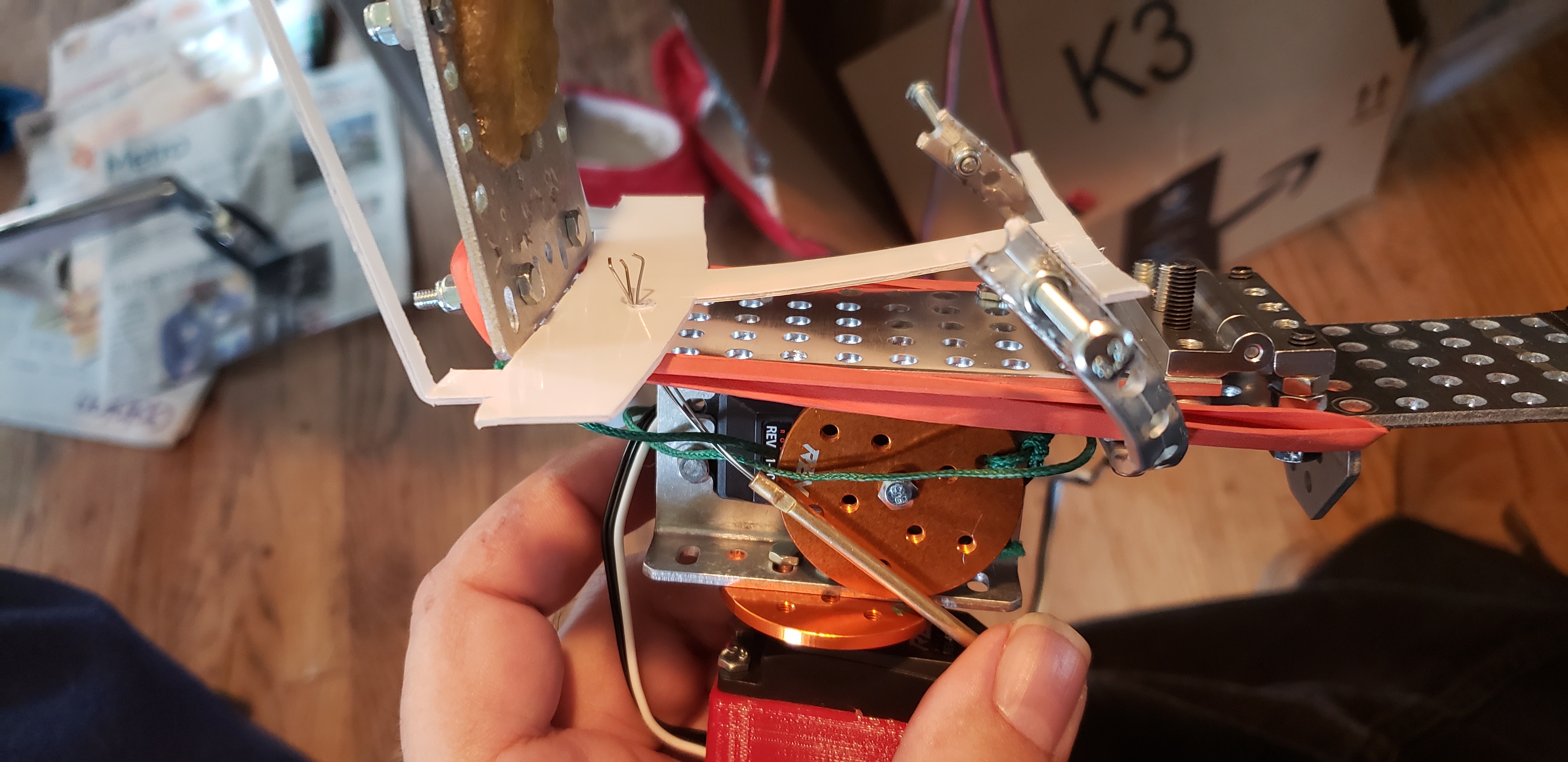
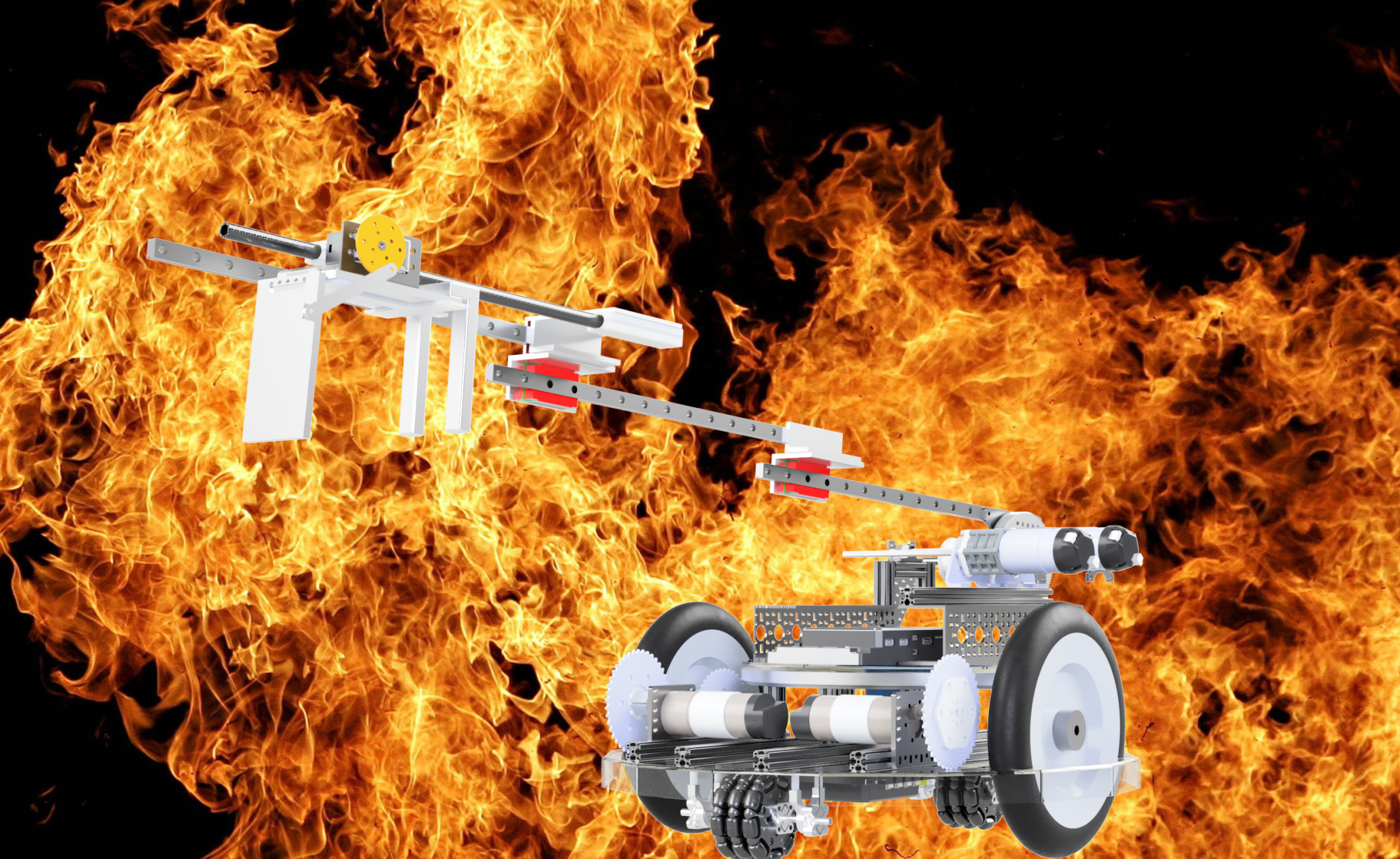
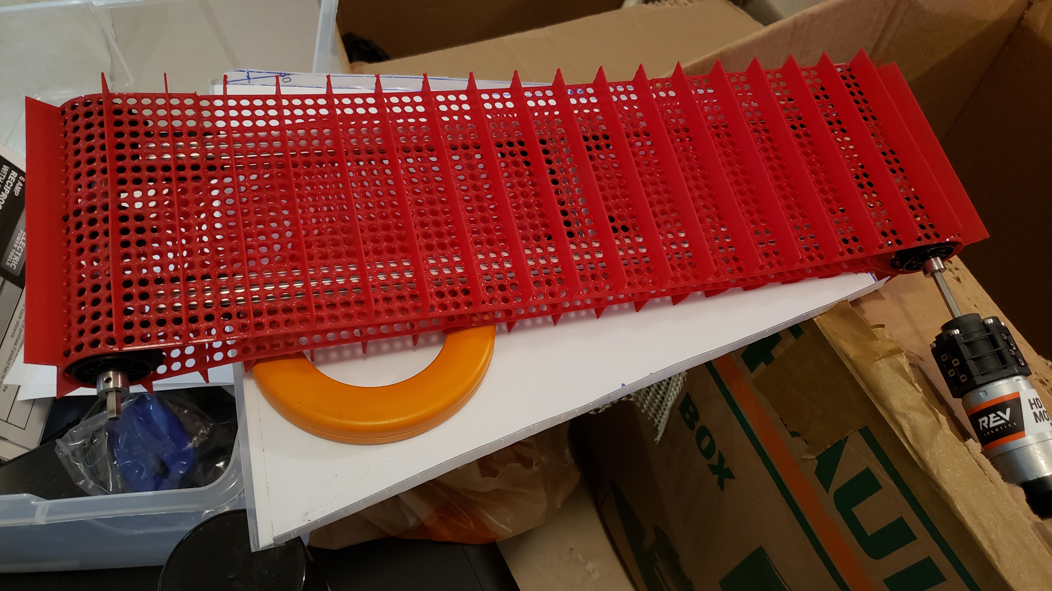
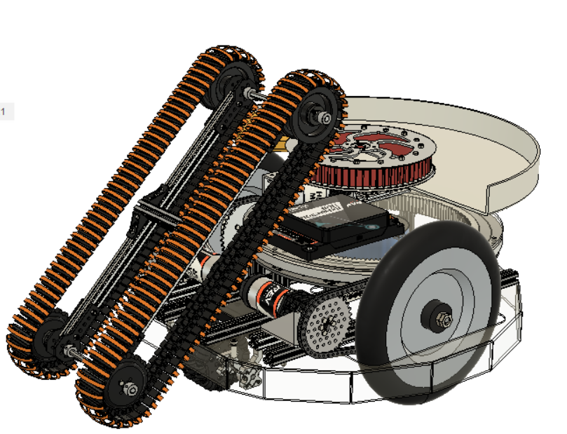
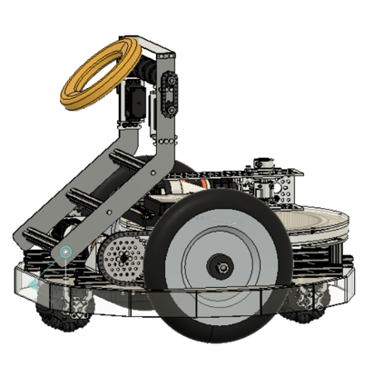
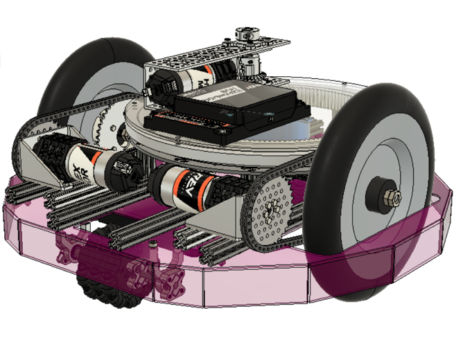
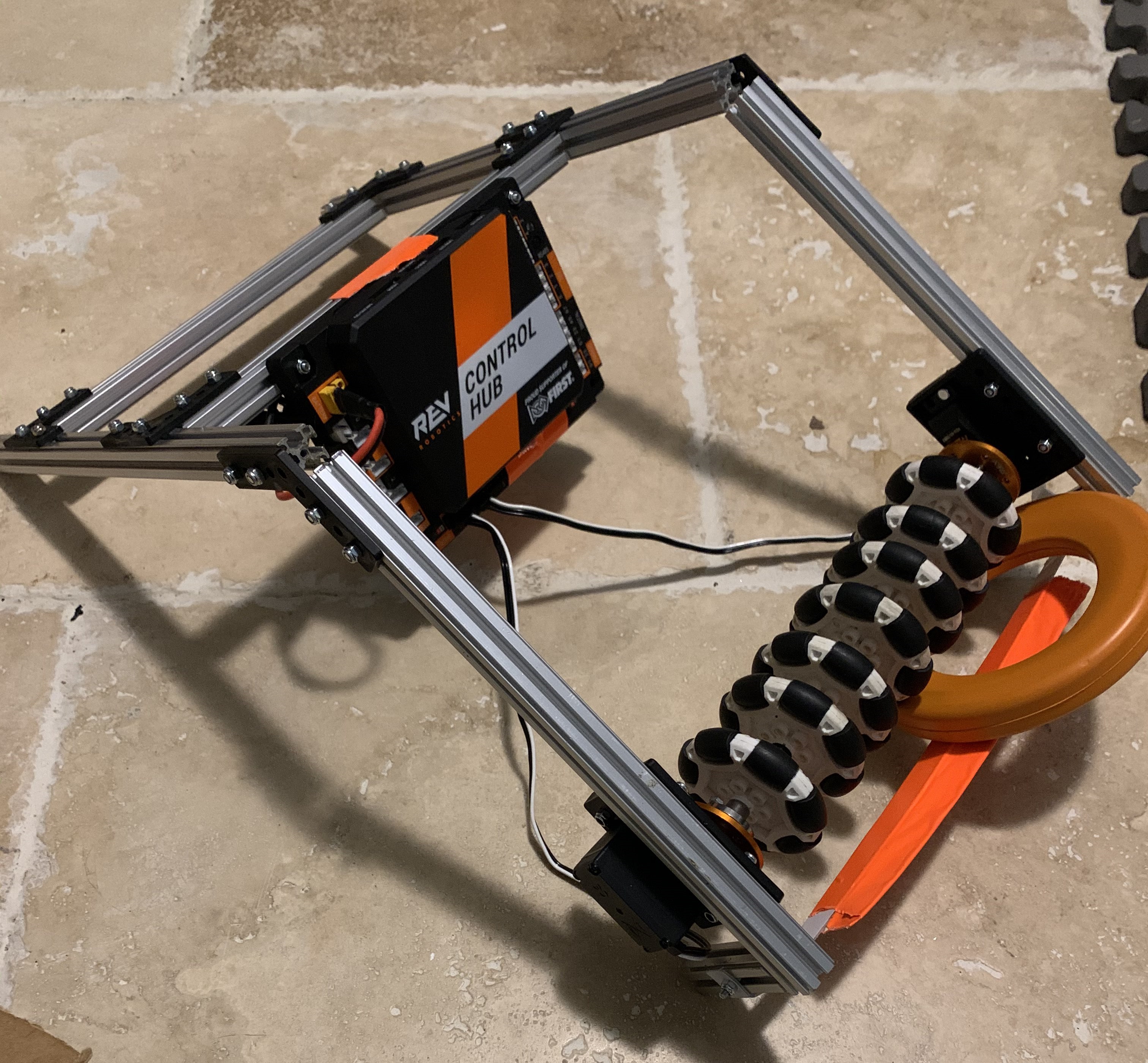
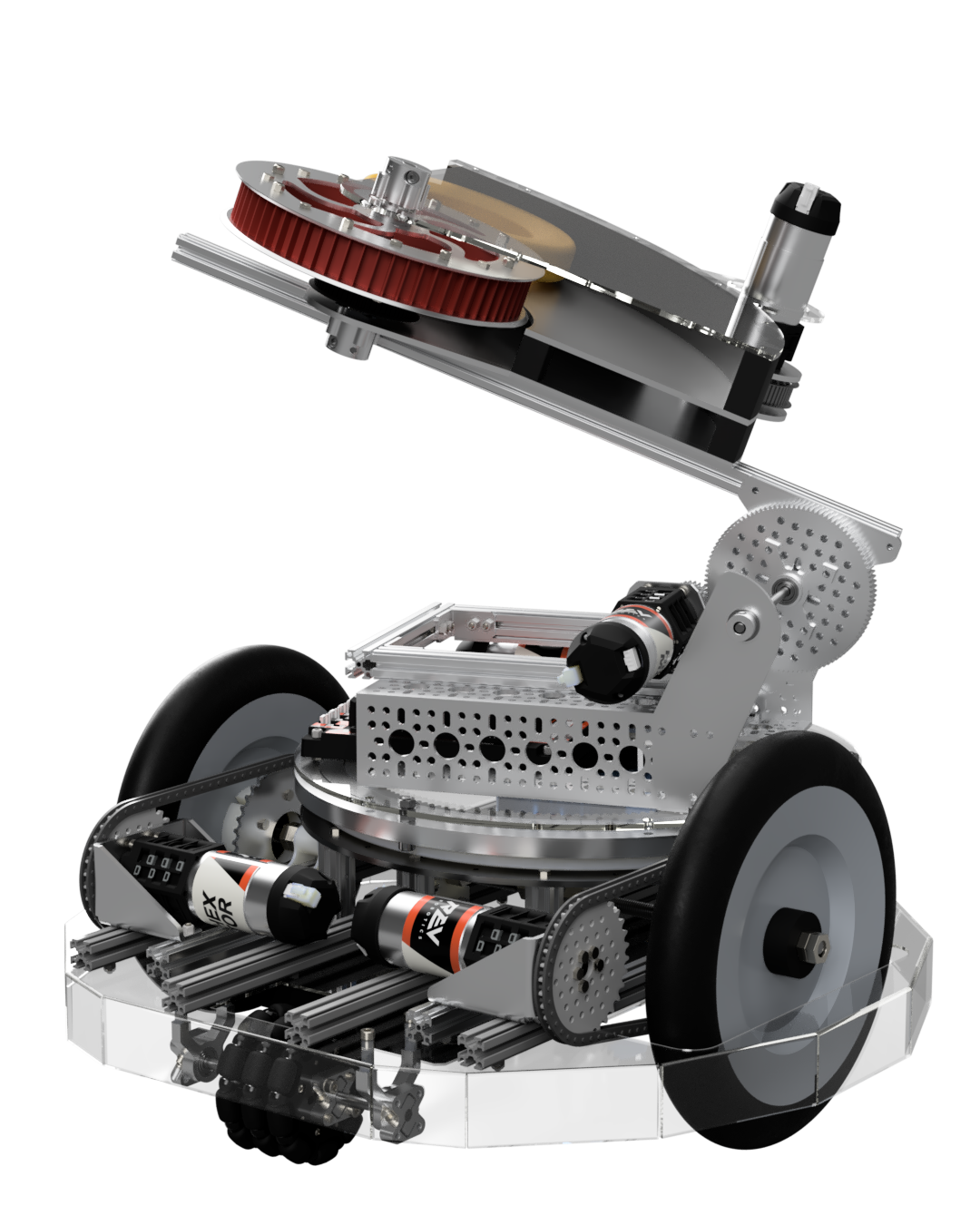
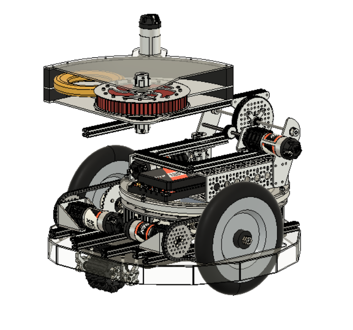
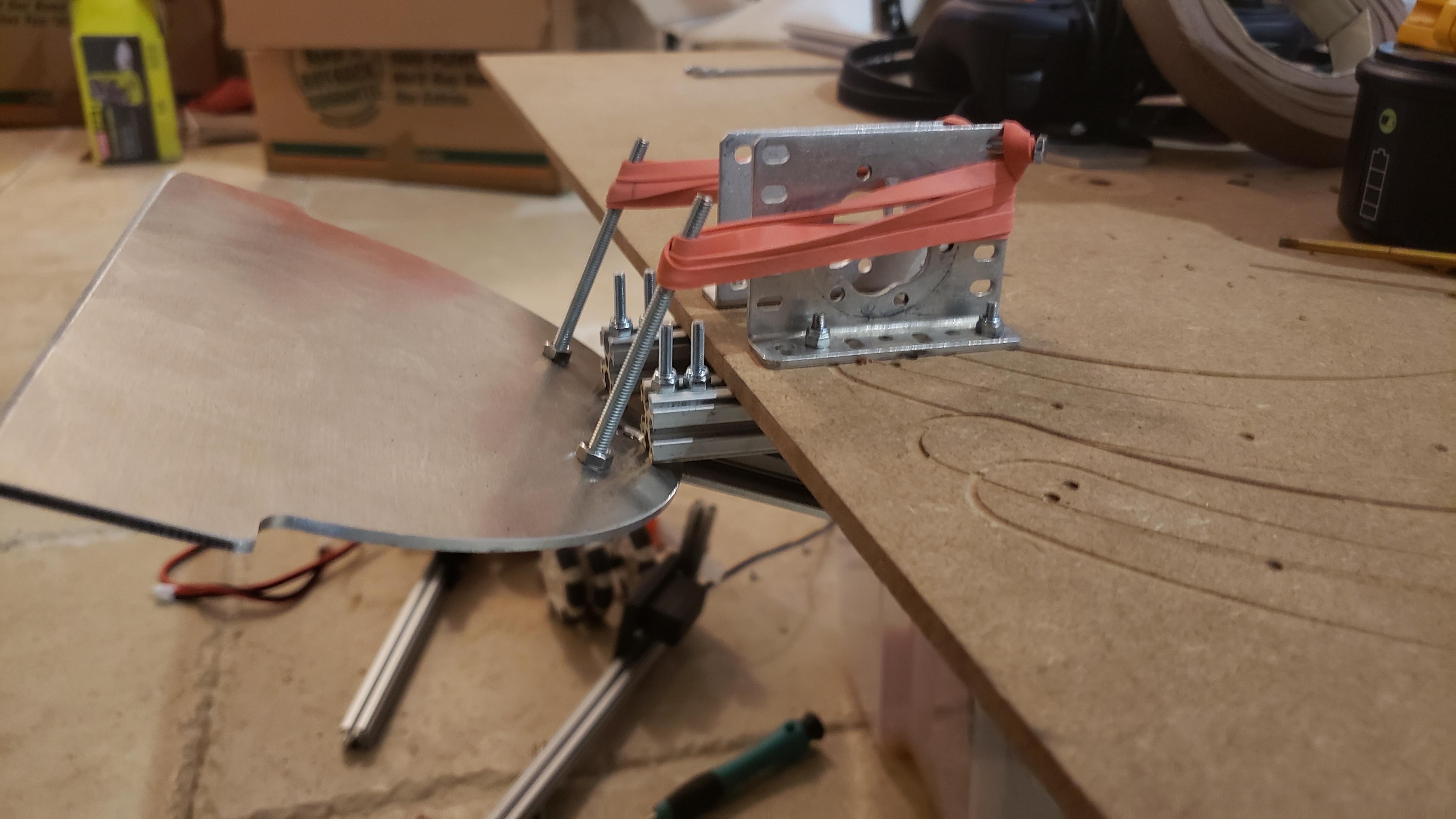
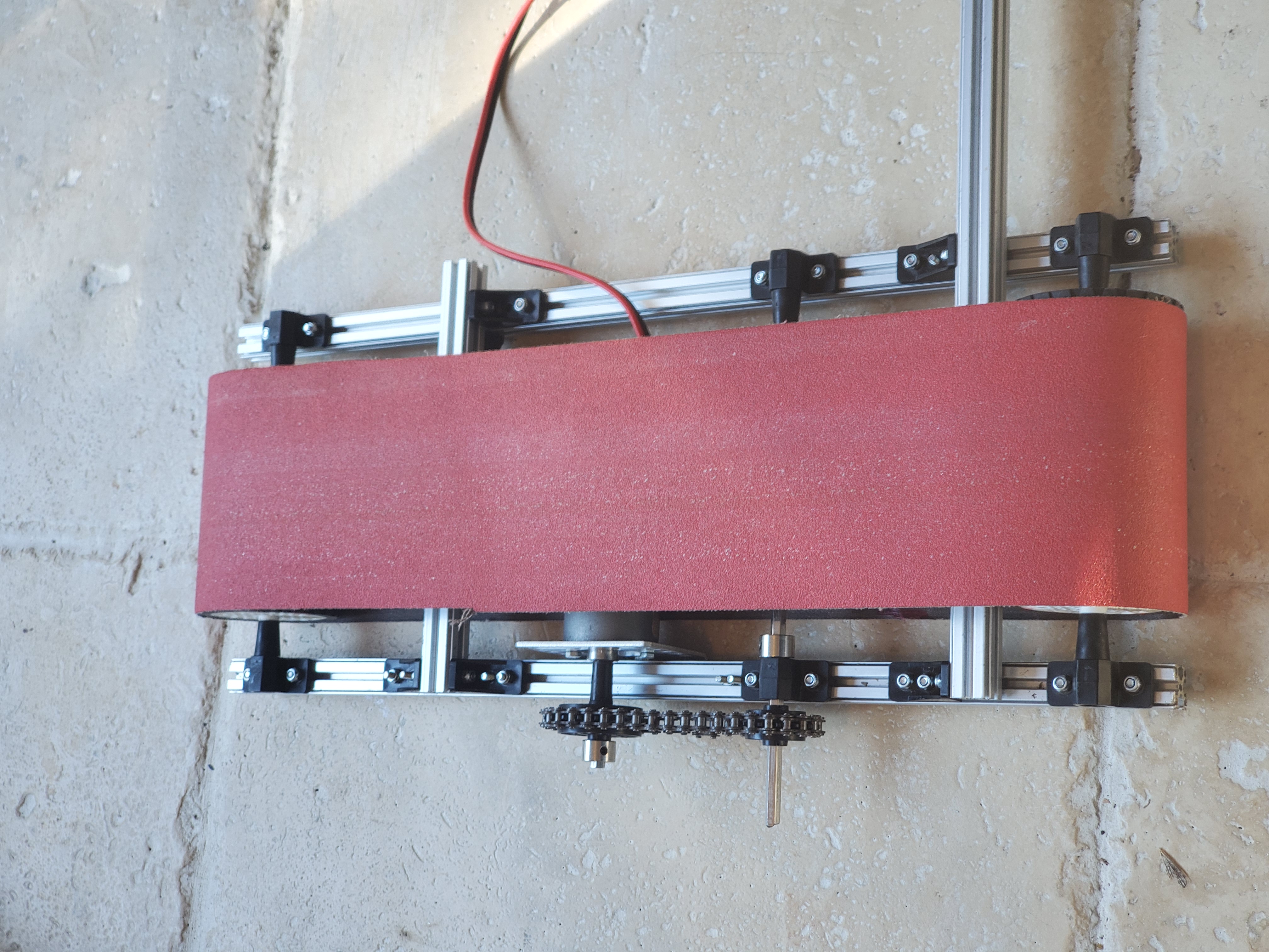
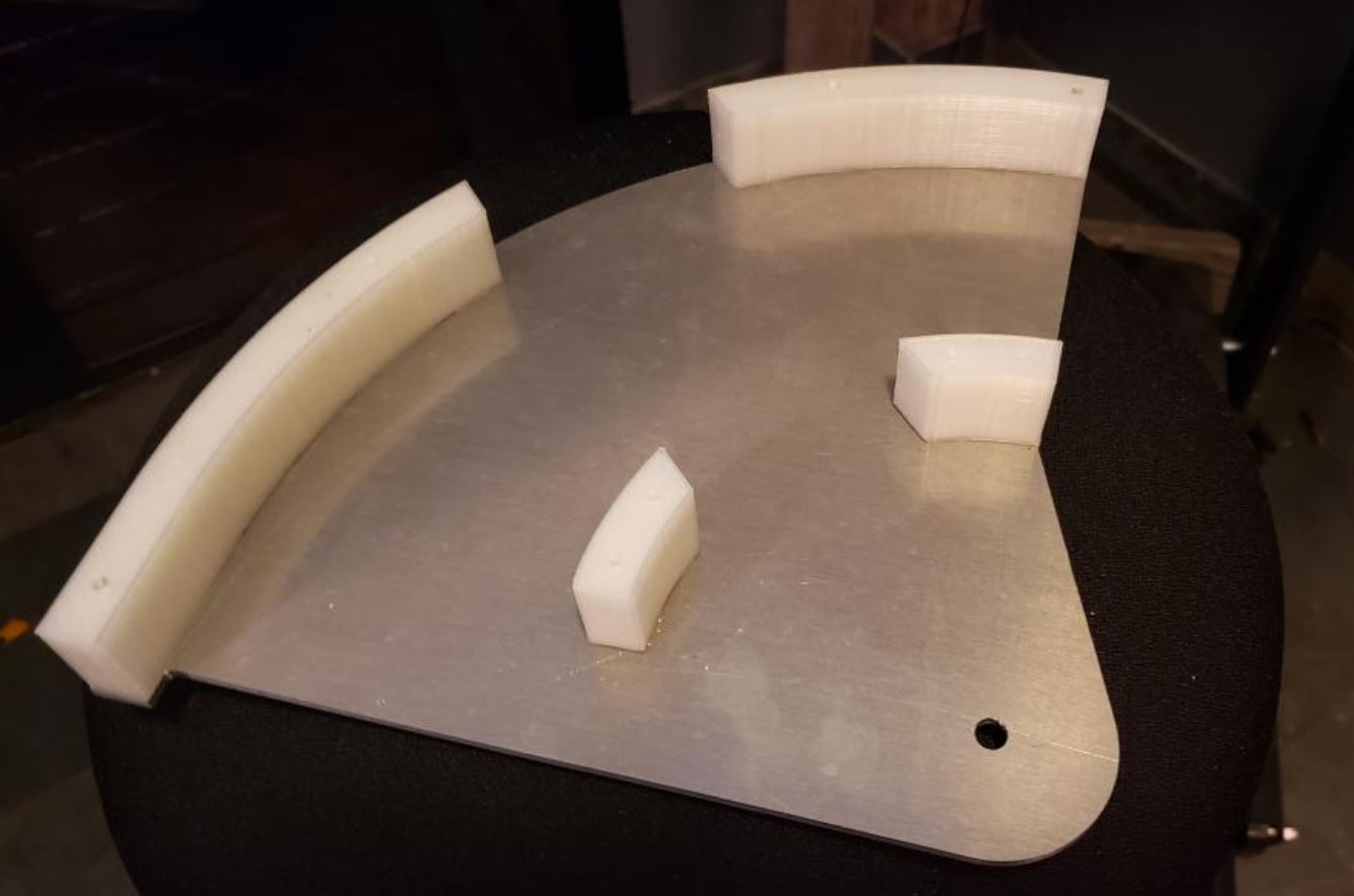
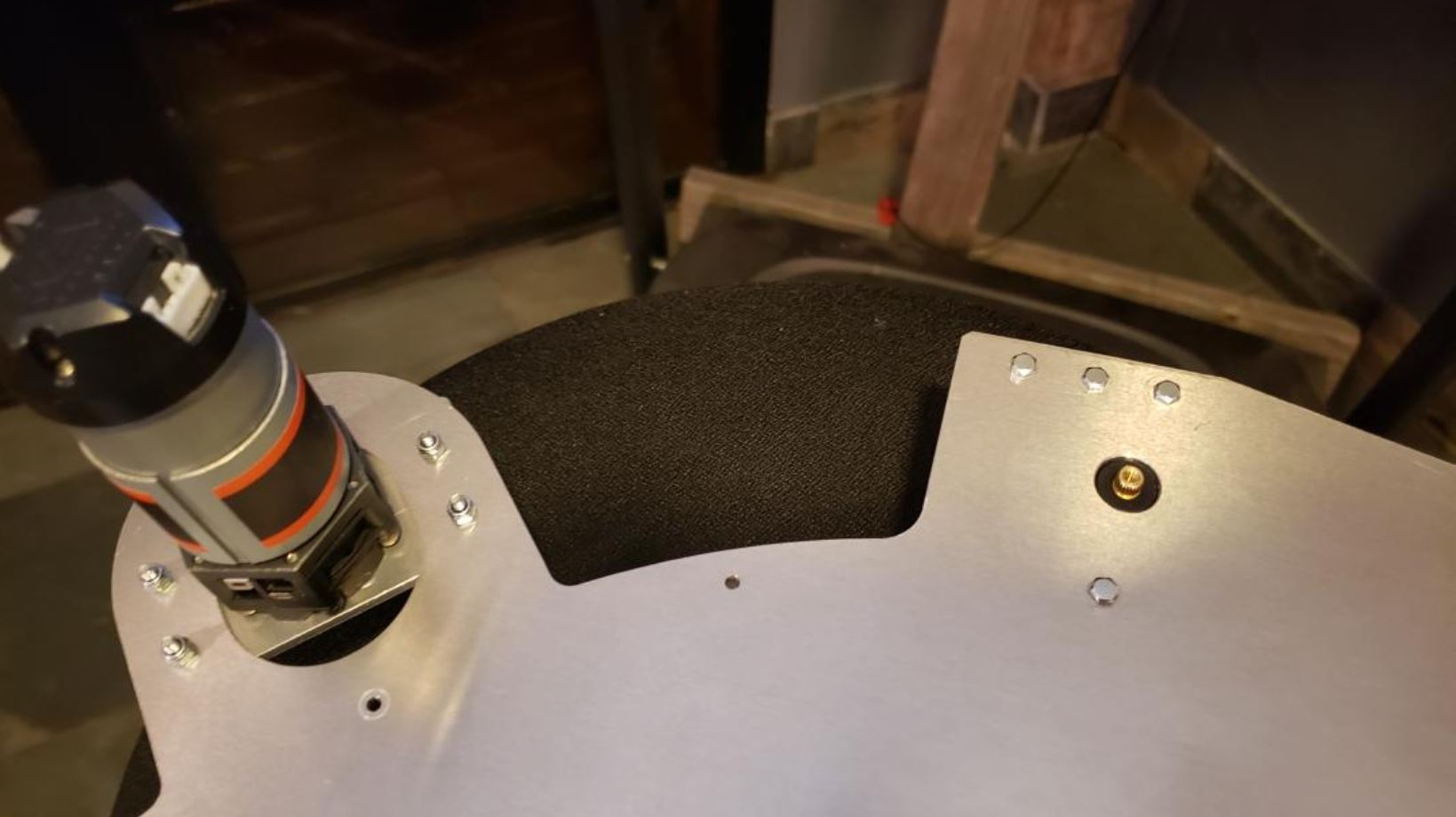
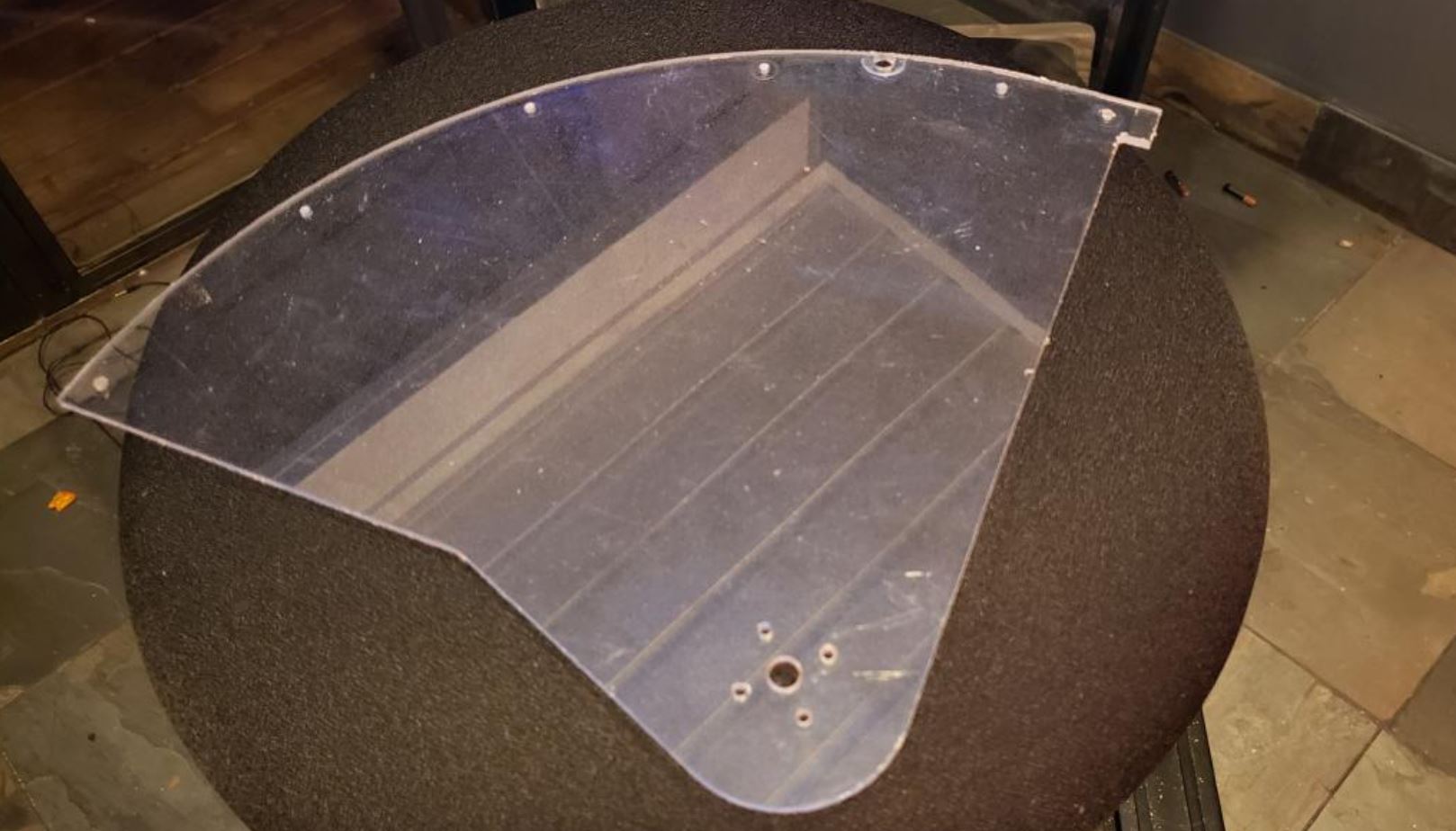
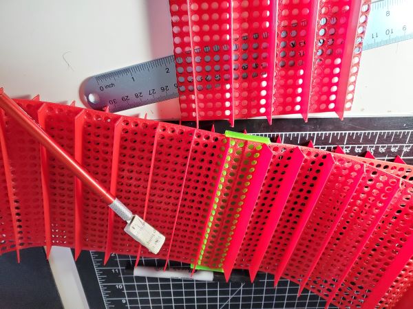
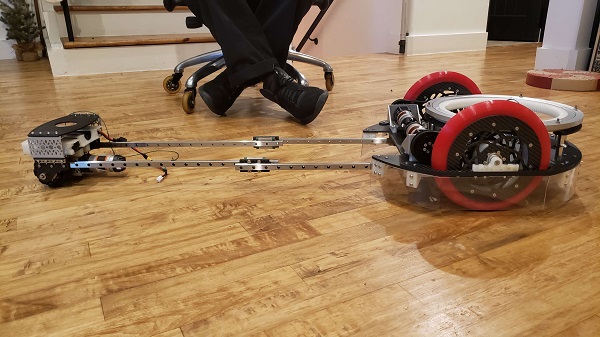
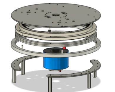
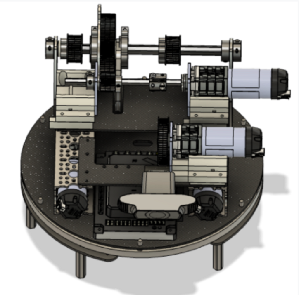
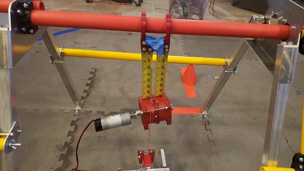
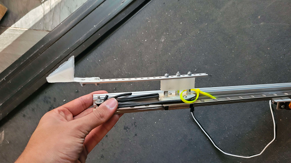
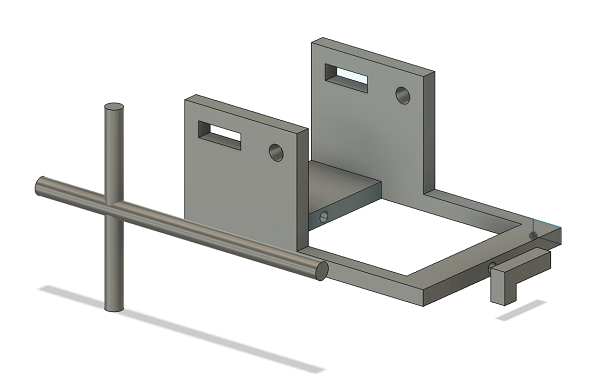
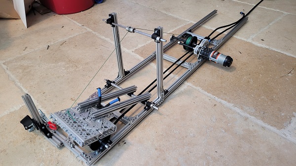
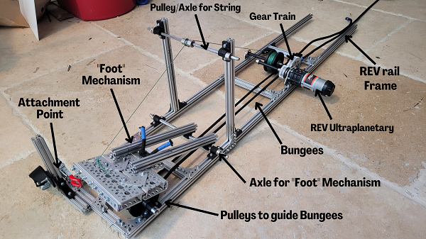
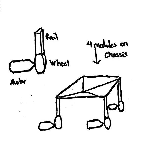
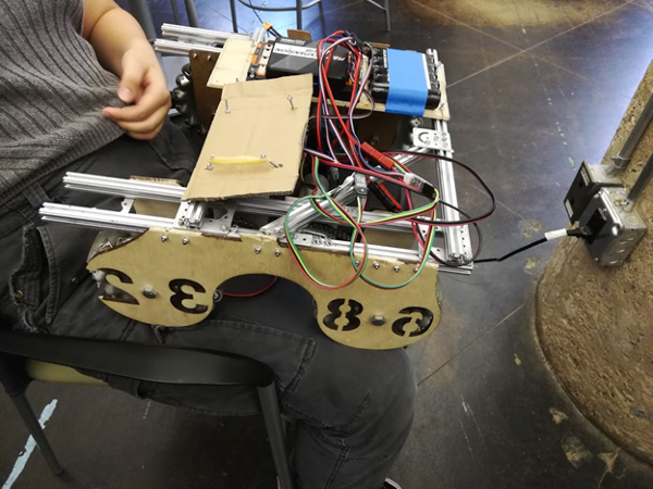
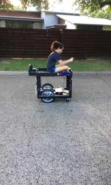
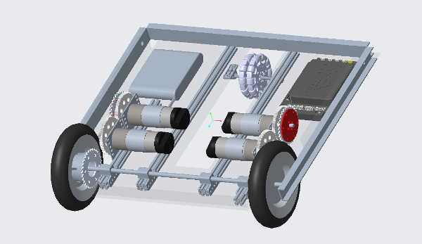
The braking subsystem consist of an approximately 2.5 foot by 7 inch REV rail frame that slides in under the driver’s console and lines up with the brake pedal. It attaches to points drilled into the flooring of the RV, and can be quickly installed. This allied for no significant permanent alterations that could interrupt our ability to drive the RV “normally.”
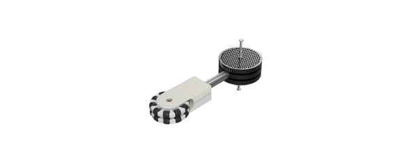
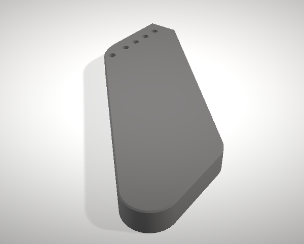
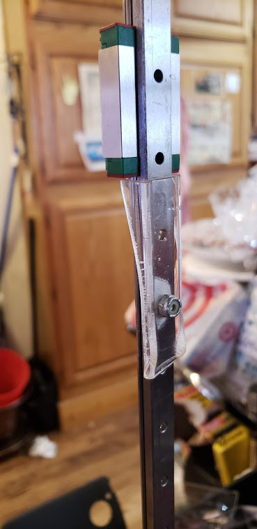
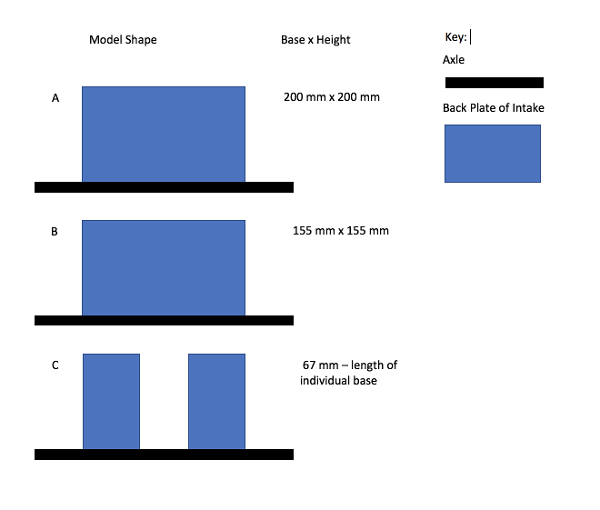
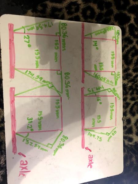
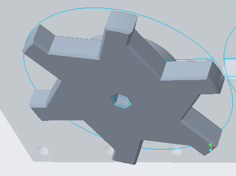
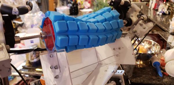
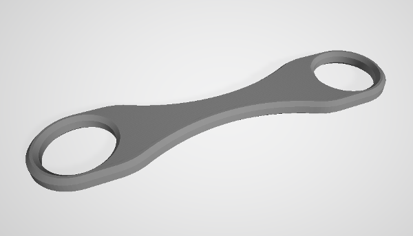
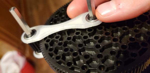
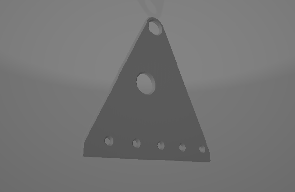
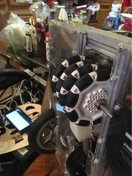
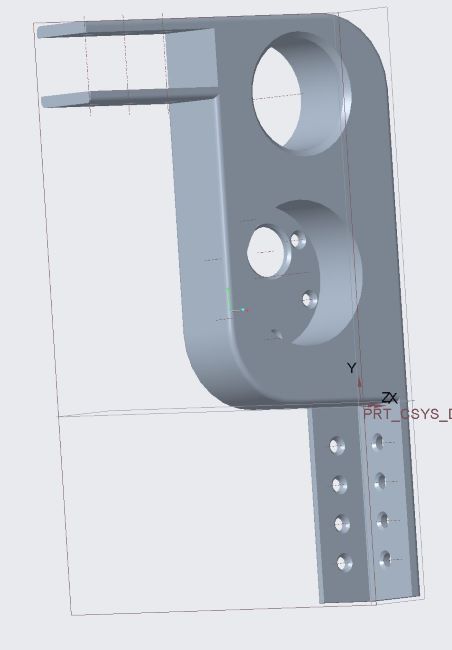
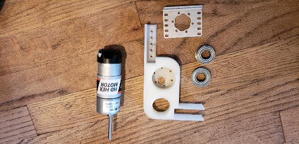
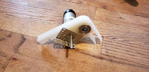
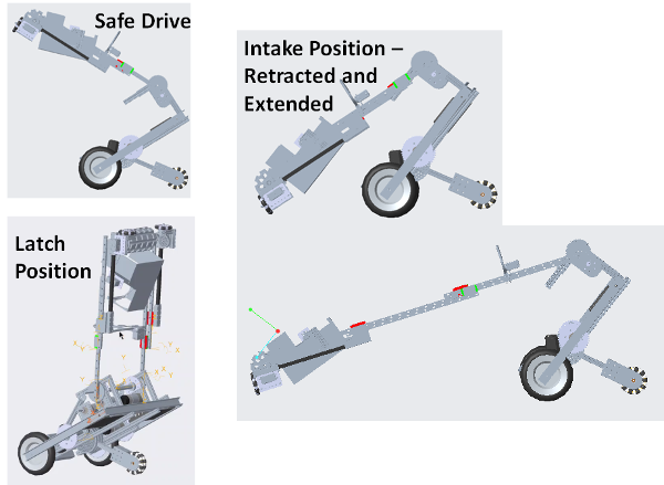
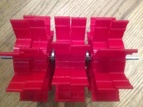
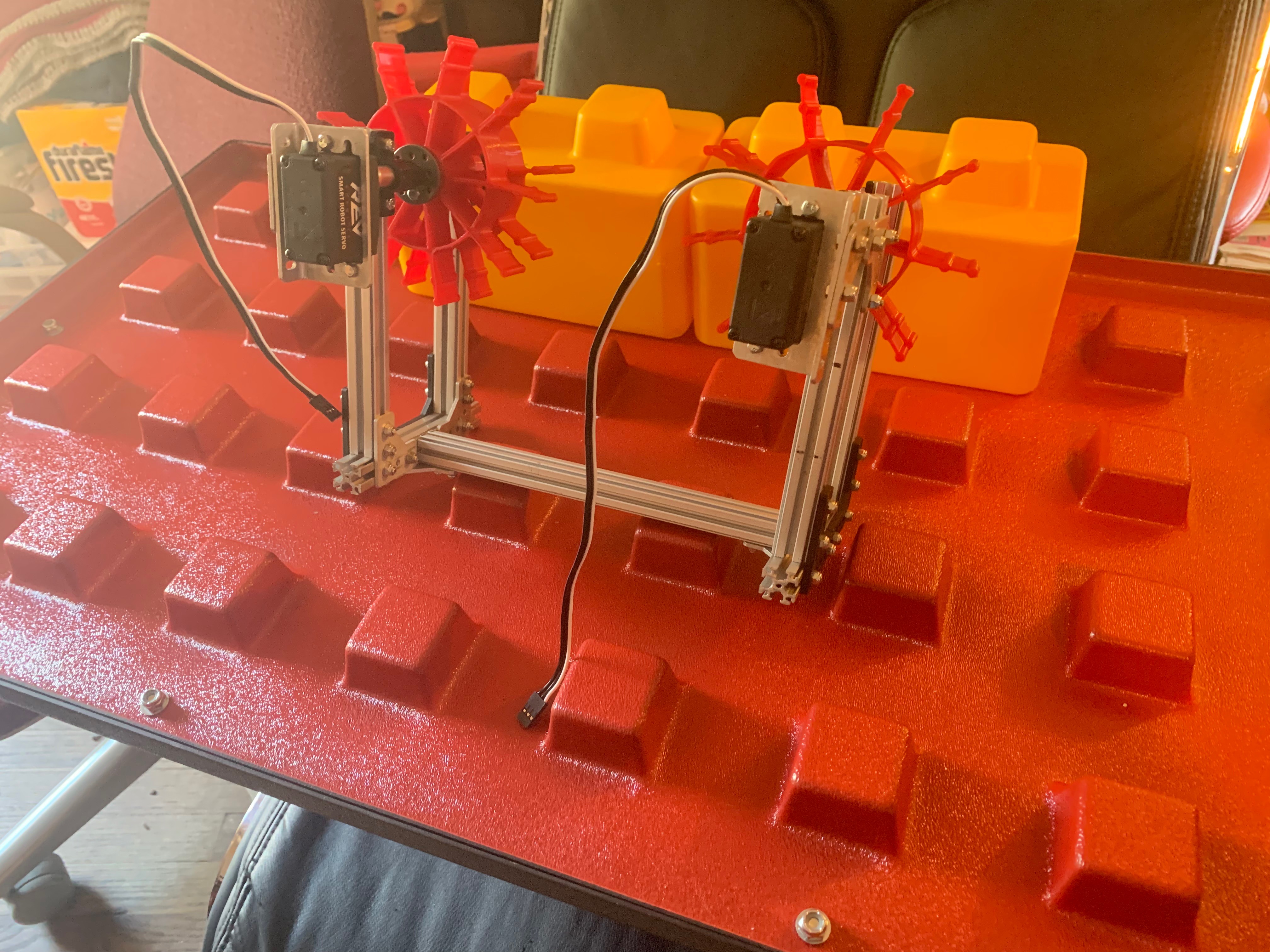
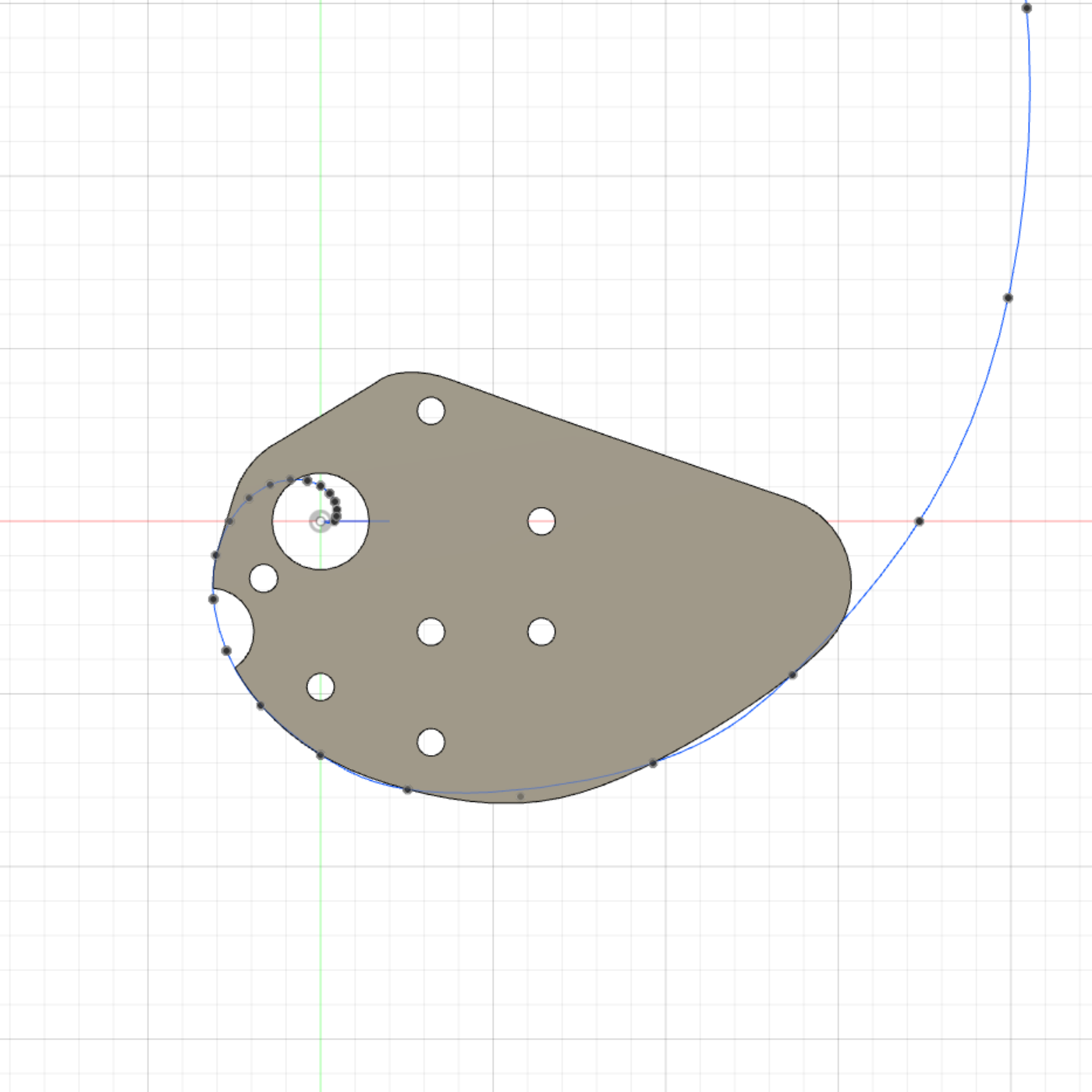
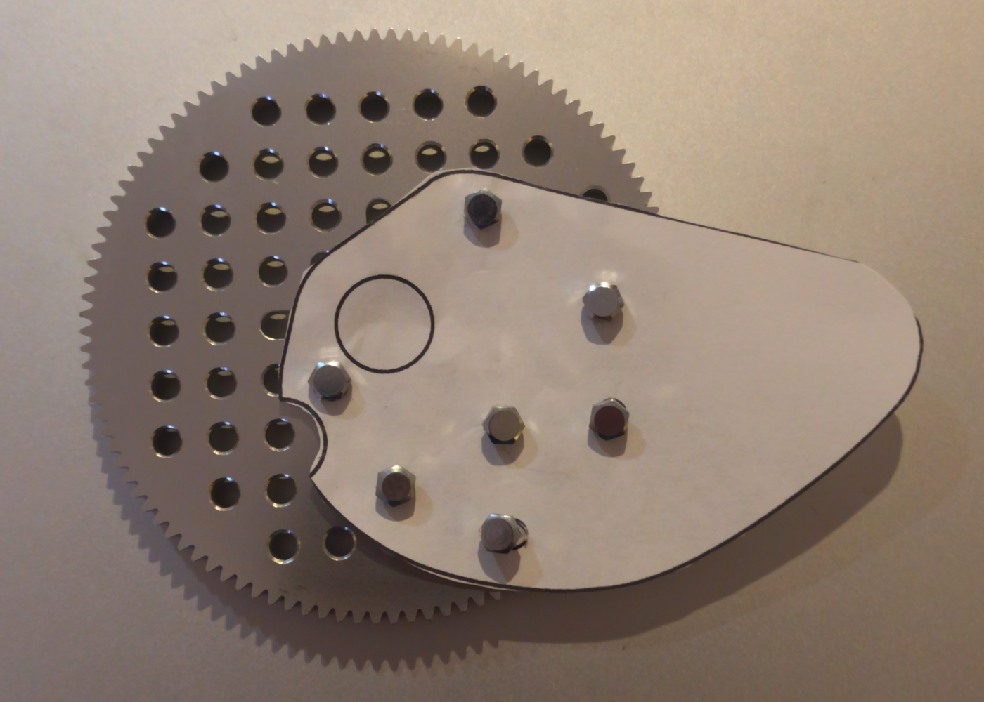
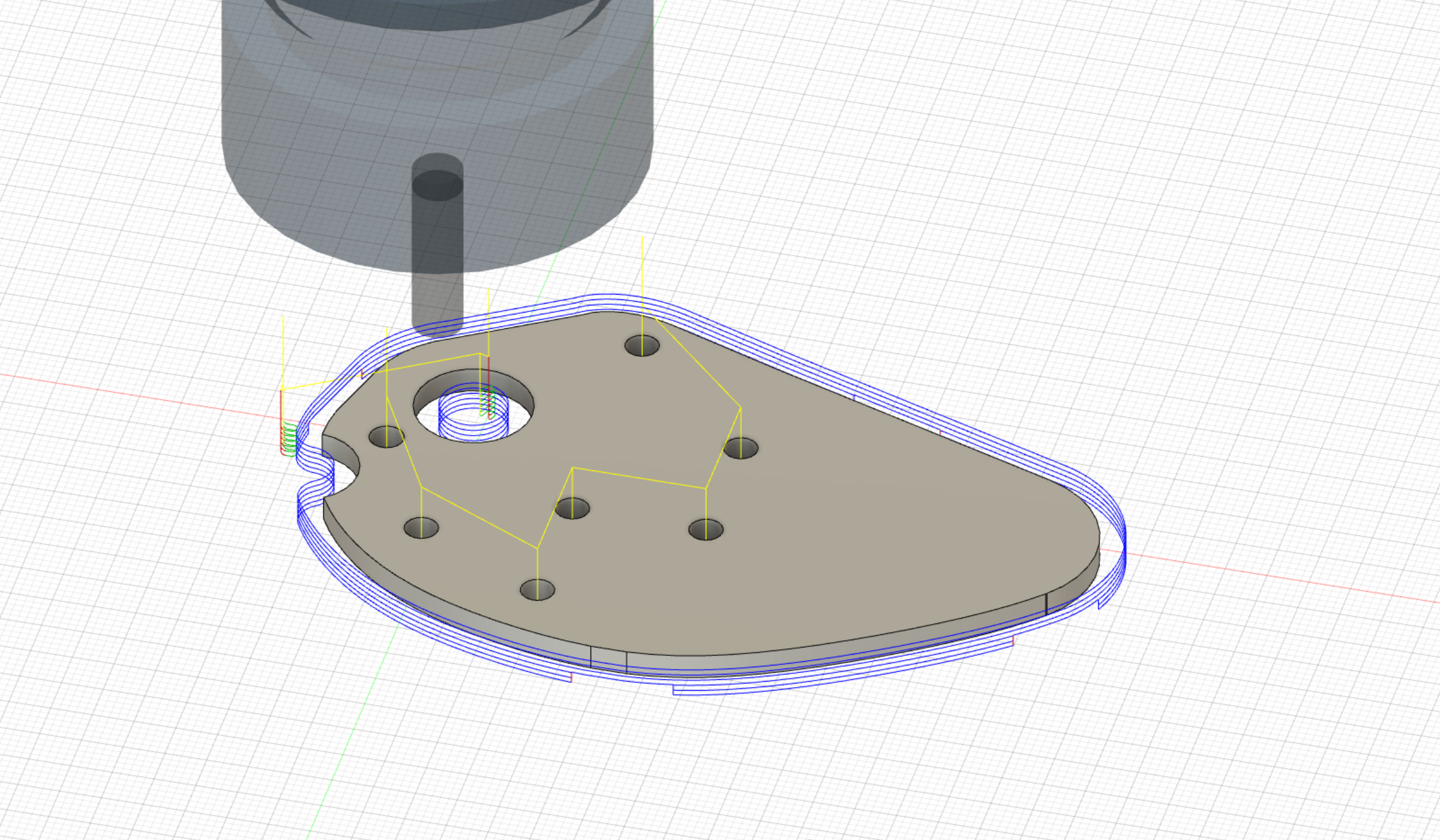
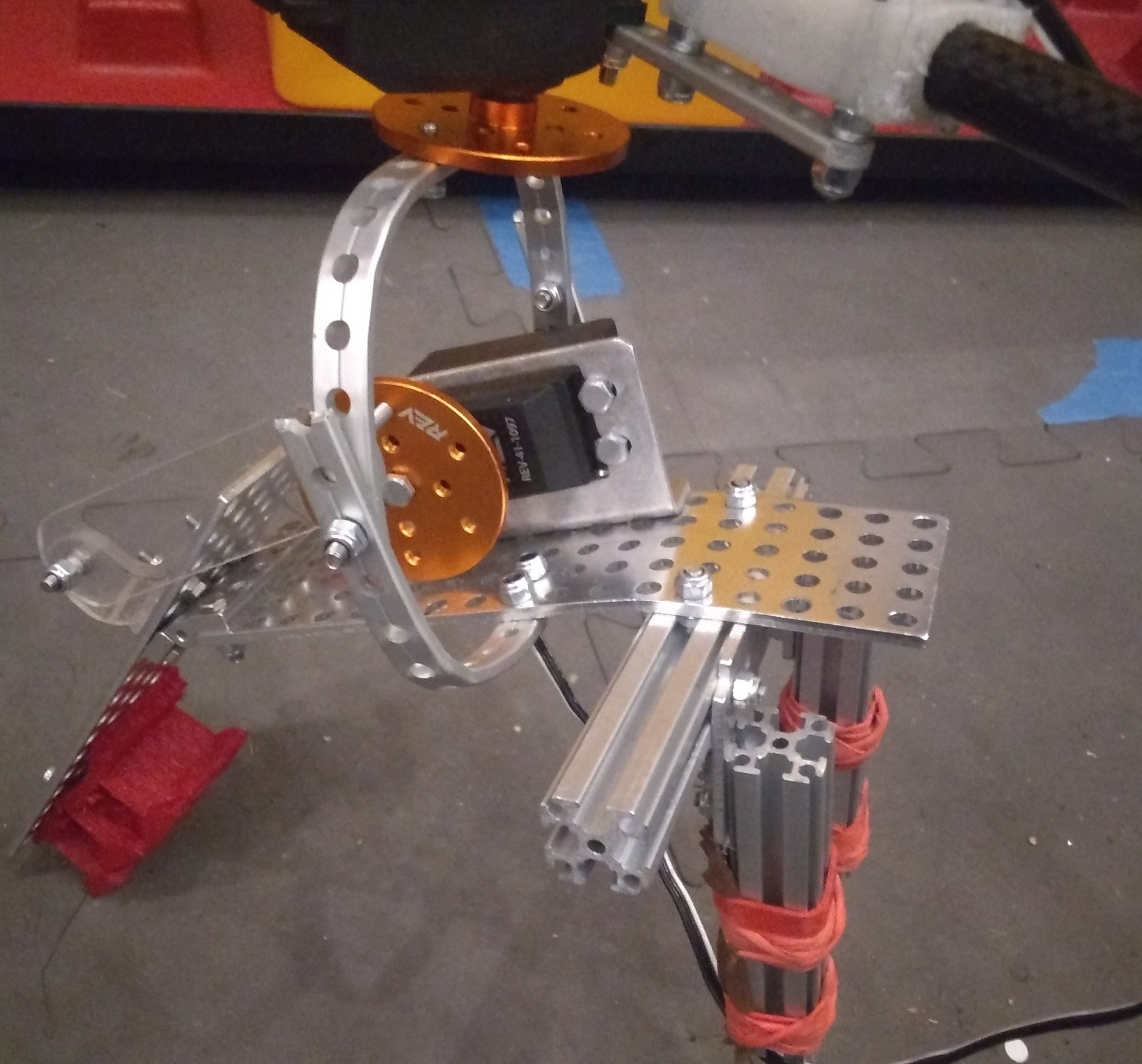
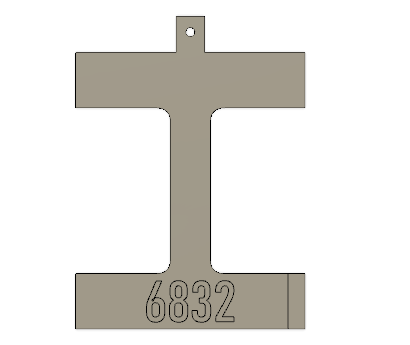
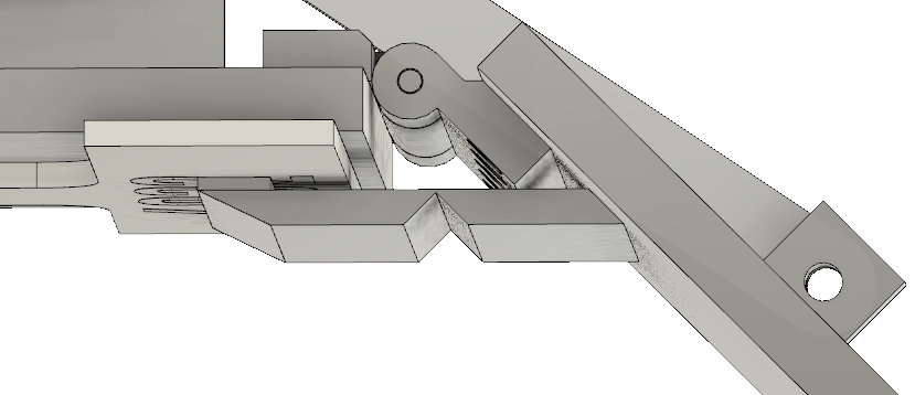
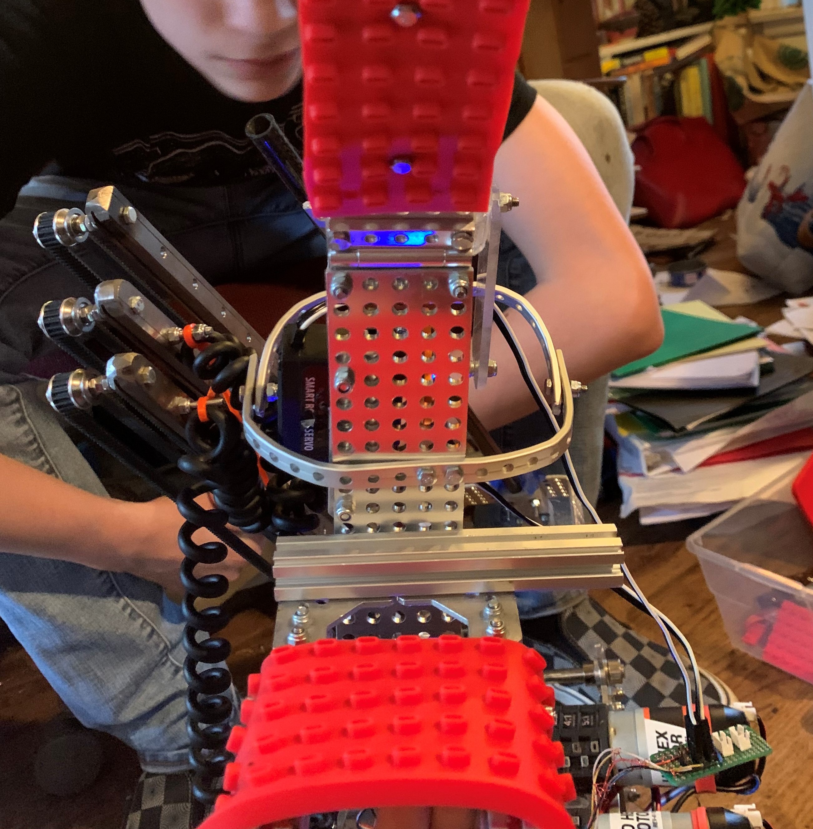
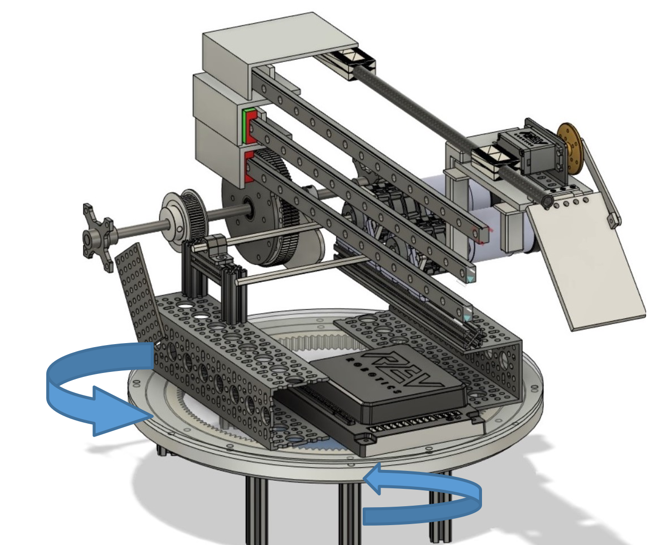
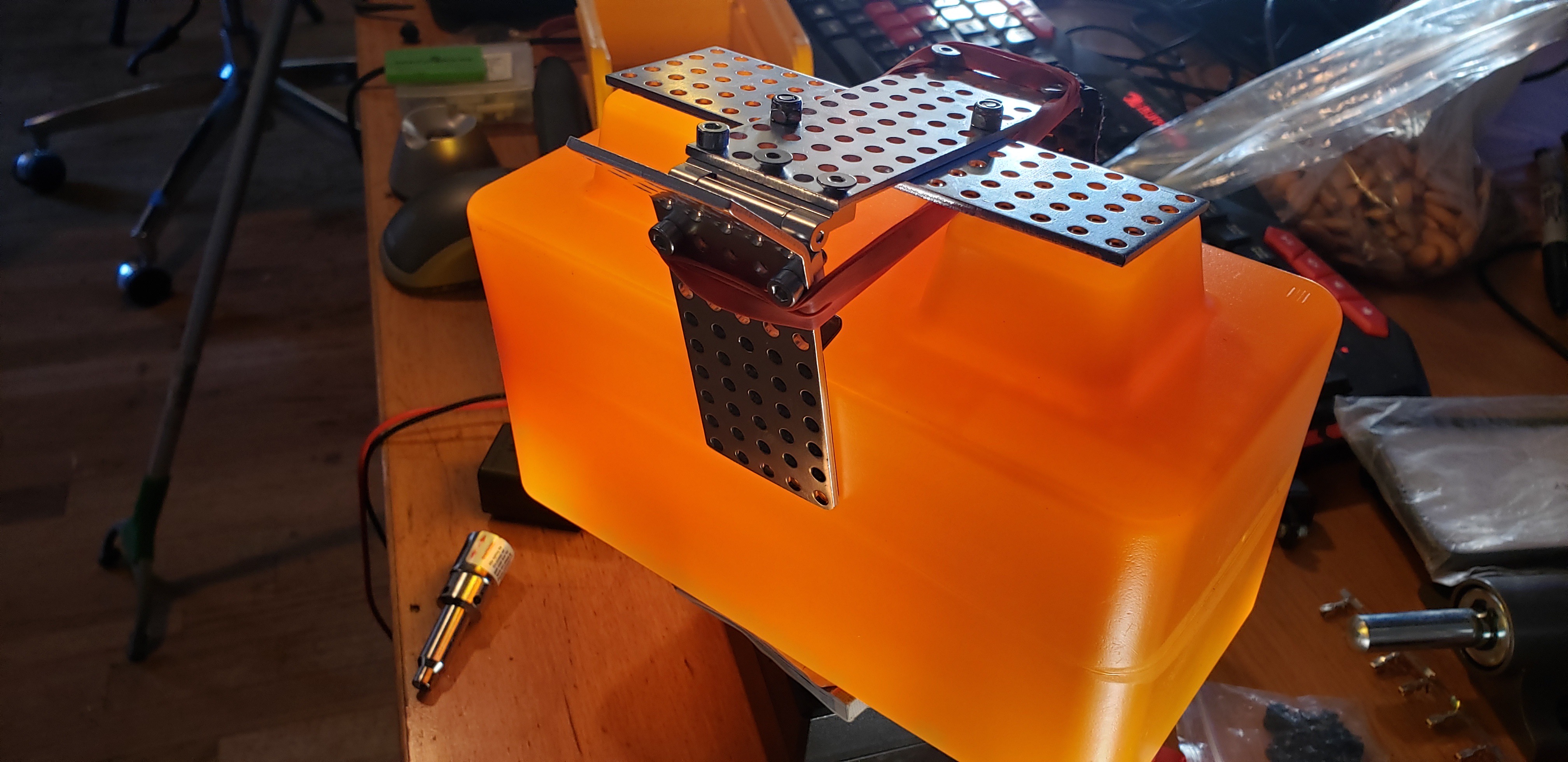
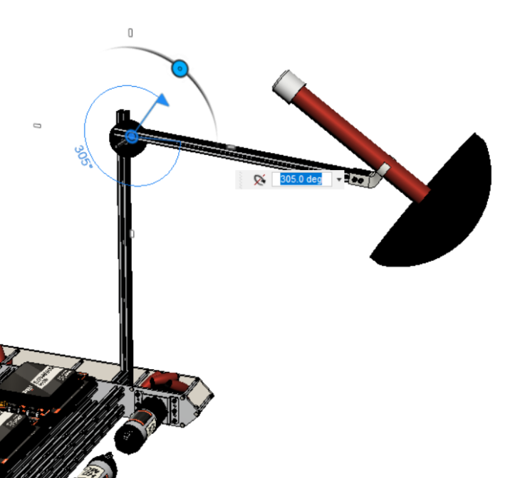
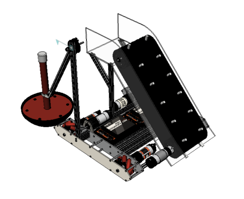
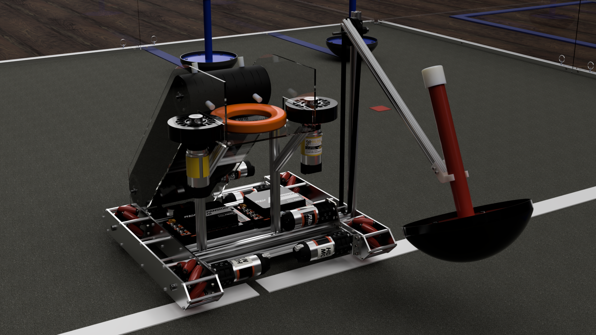
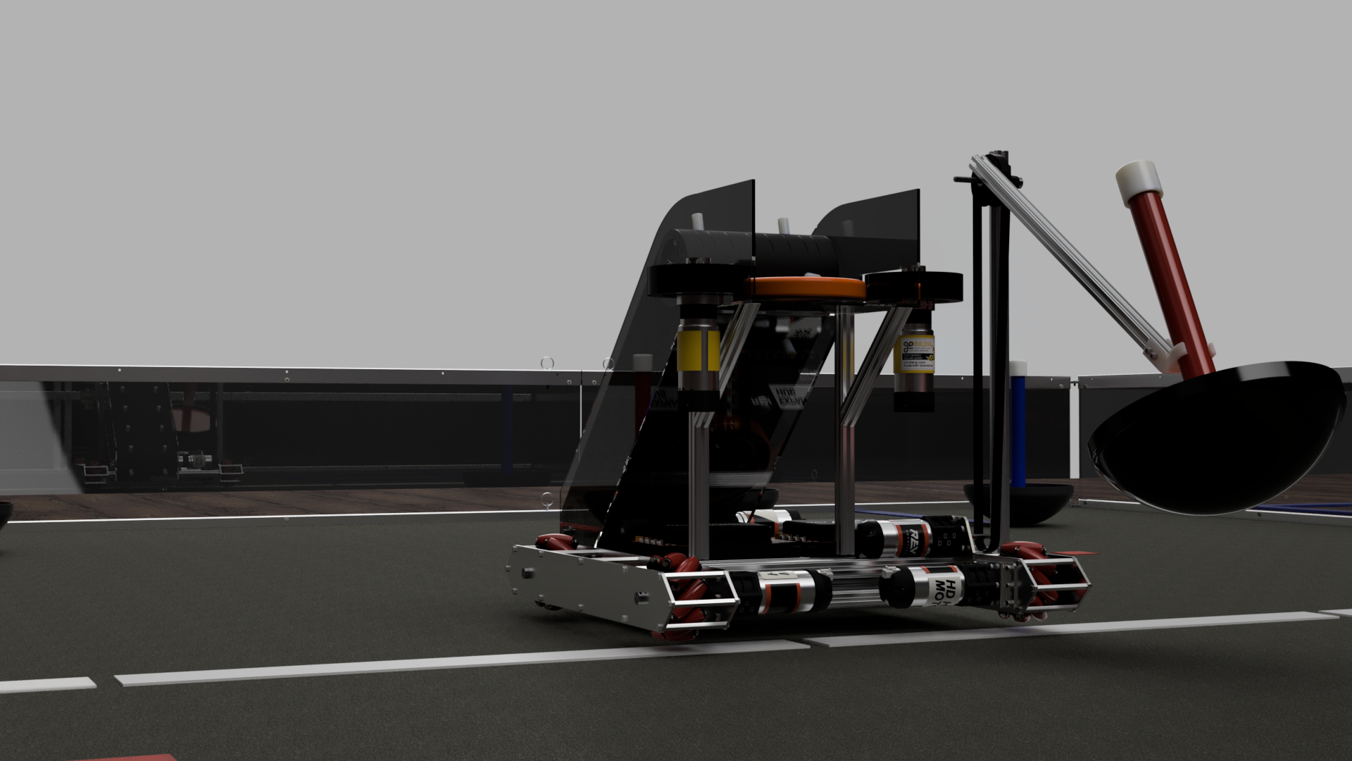
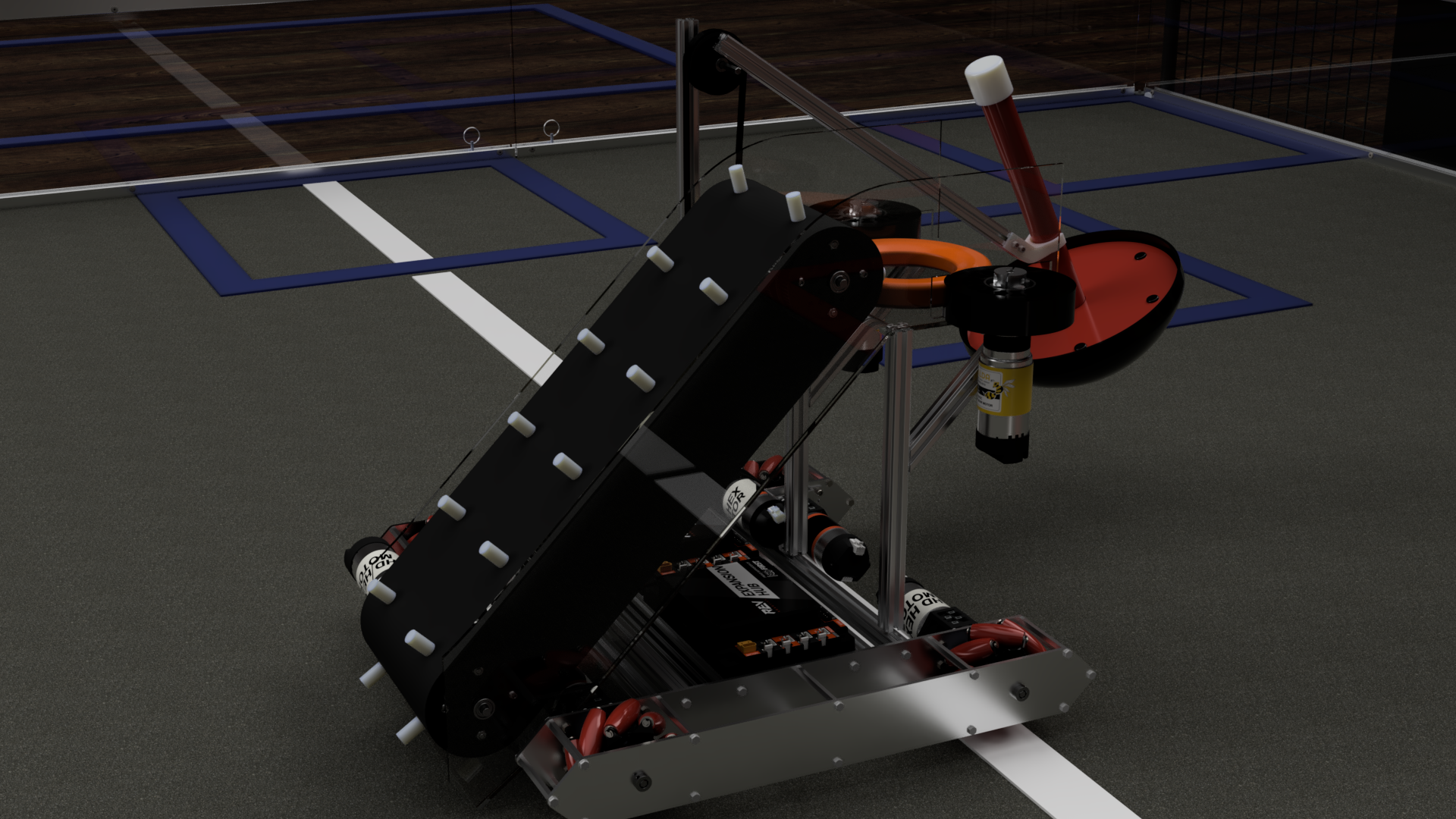
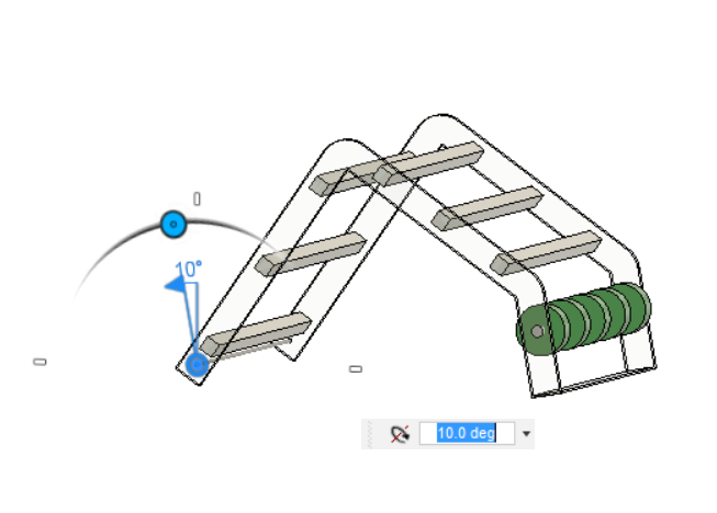
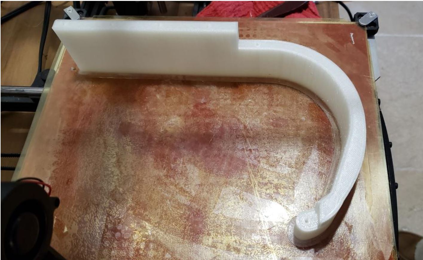
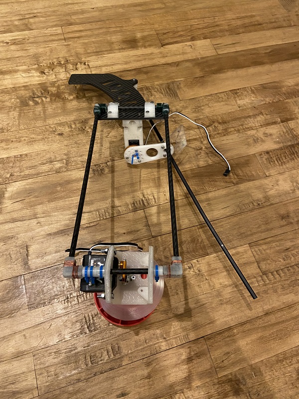
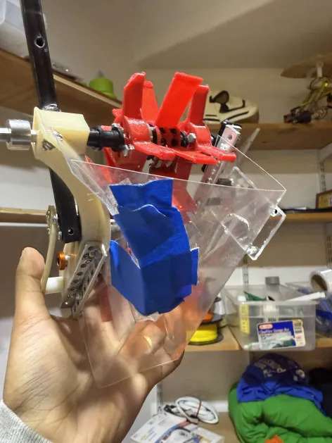
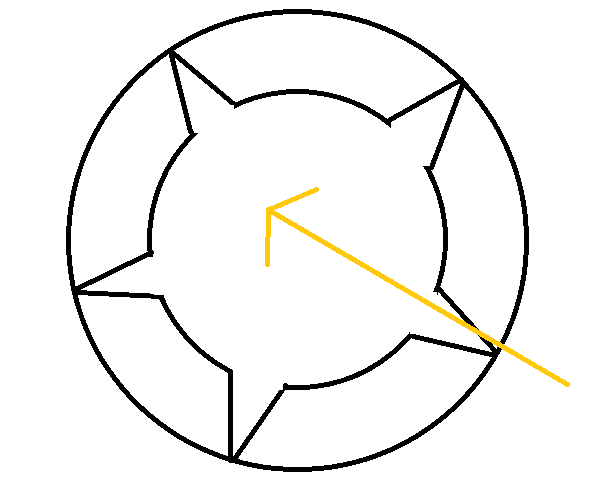
On the frame, there is a “foot” mechanism mean to simulate the movement of a foot that presses the brake by rotating on an axle attached to the frame. This “foot” is what we manipulate in order to press and release the brake.
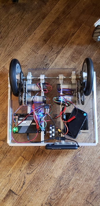
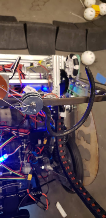
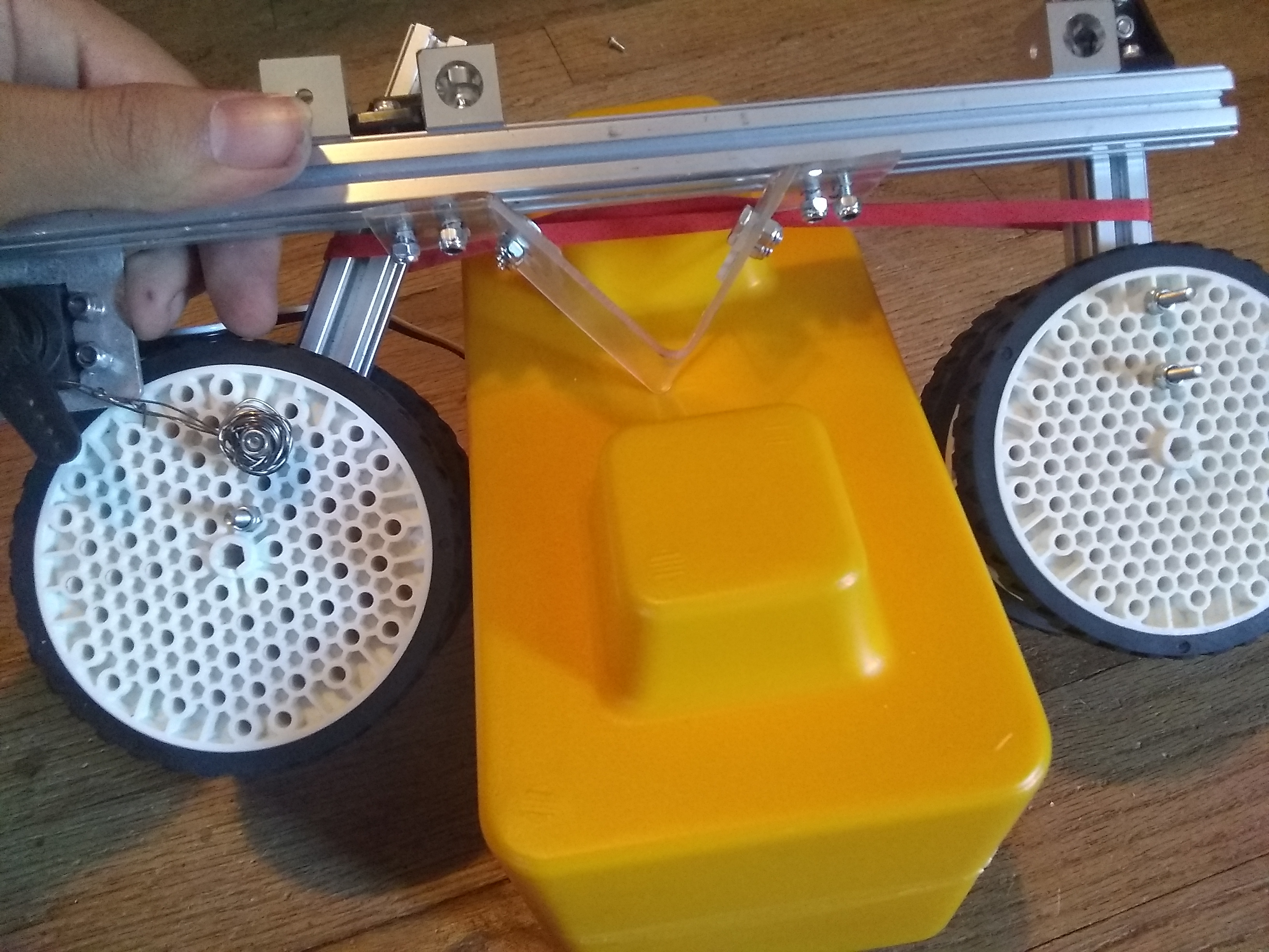
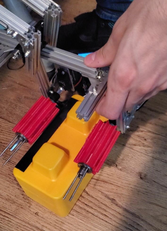
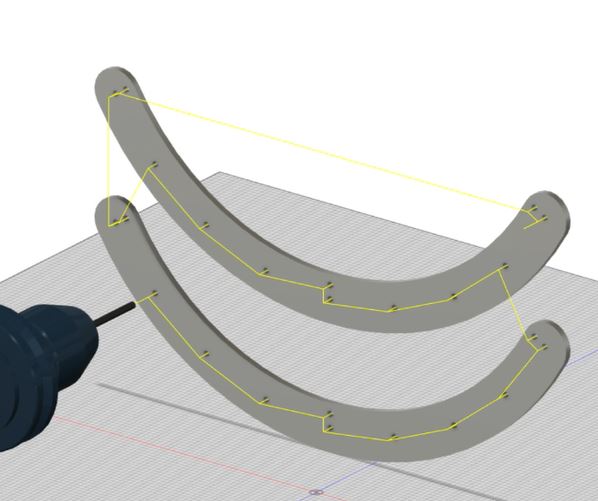
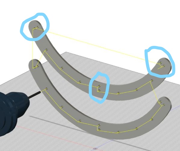
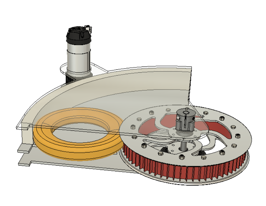
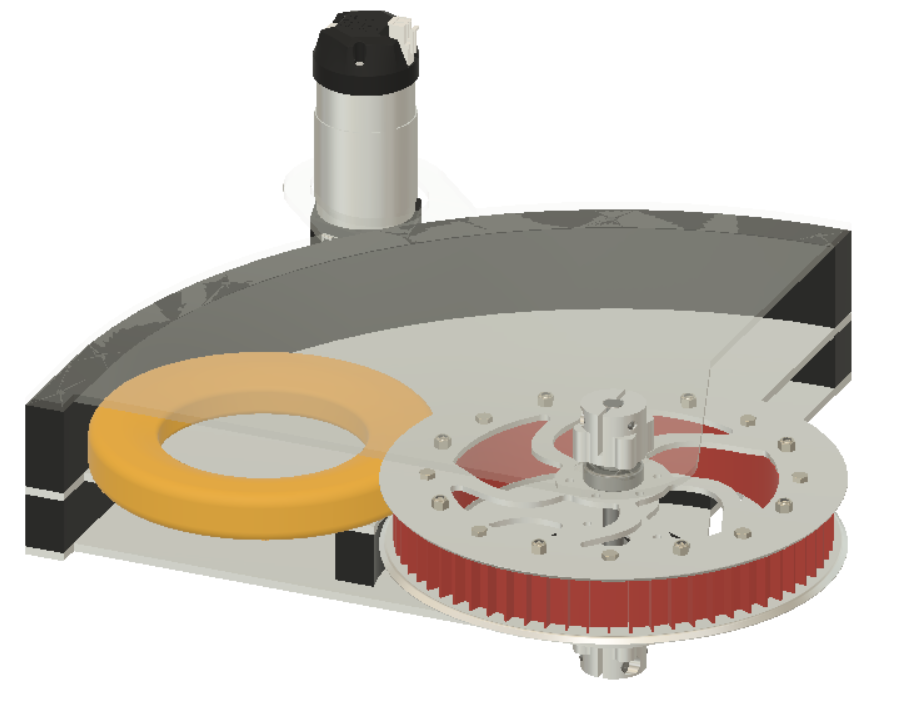
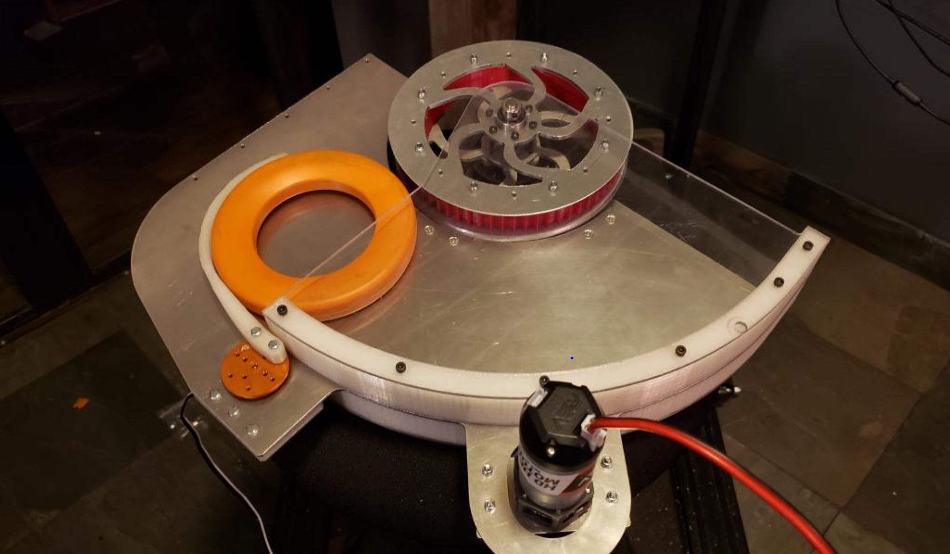
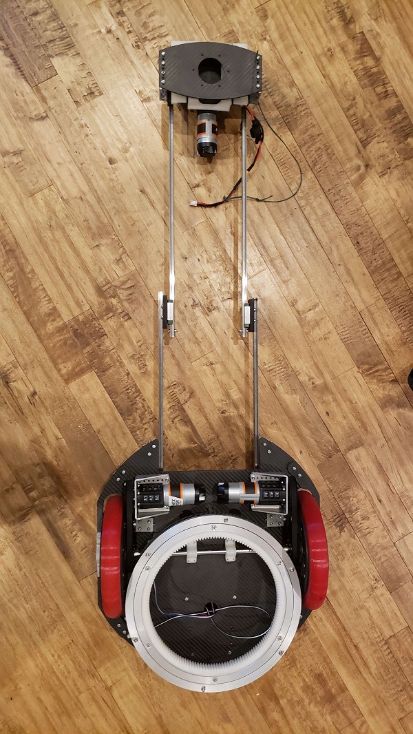
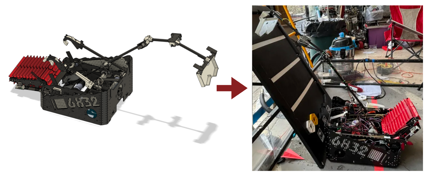
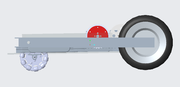
In order to set the default position of the foot mechanism to down, a system of bungees and pulleys are used to create tension and pull the brake down. This way, if the system ever loses power or fails, the foot will revert to pressing the brake and stopping the vehicle. The bungees are tied to the front of the foot and pass through a set of pulleys that send them to the back of the frame, where they are securely tied down. These bungees create a significant amount of tension in order to ensure the foot presses the brake far enough to stop the vehicle.
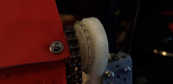
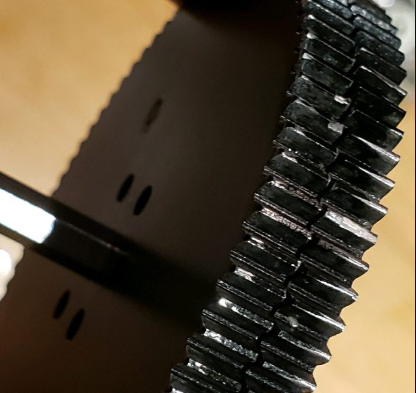
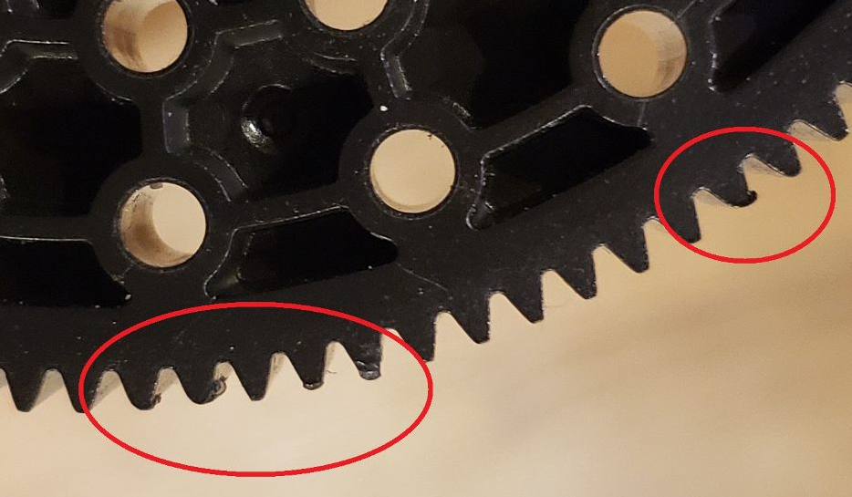
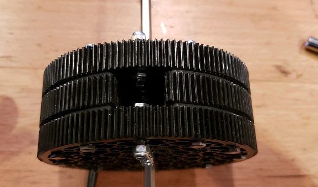
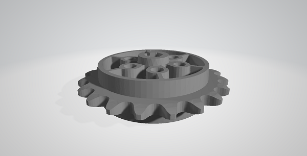
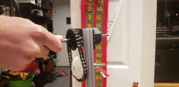
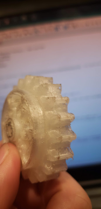
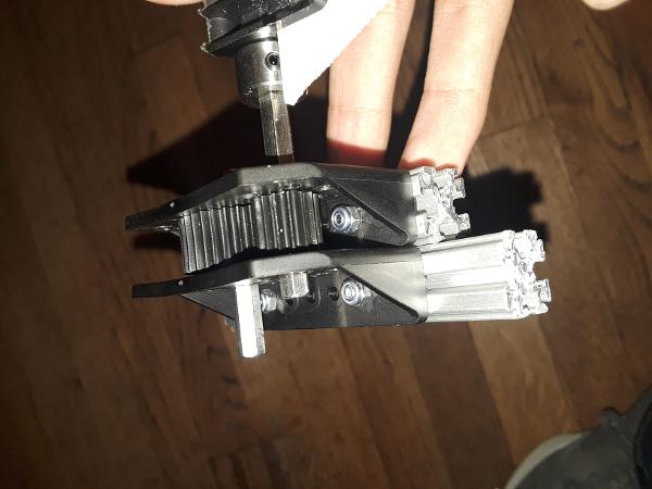
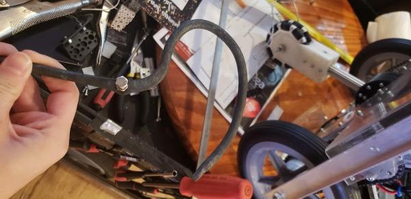
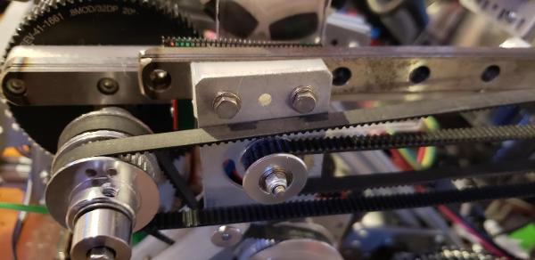
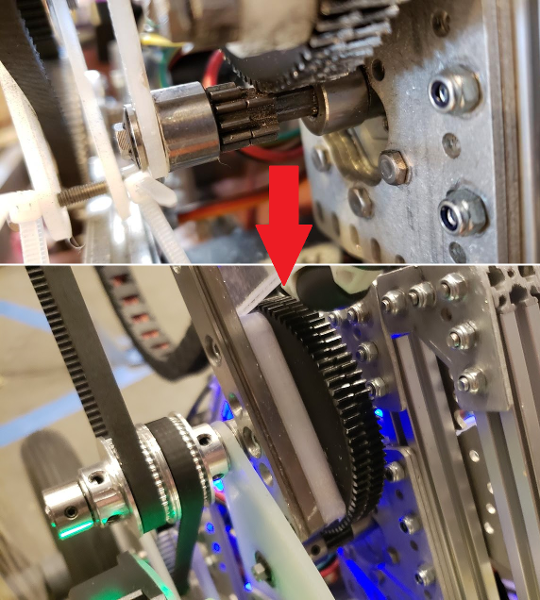
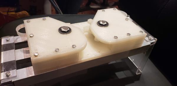
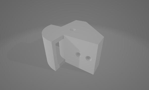
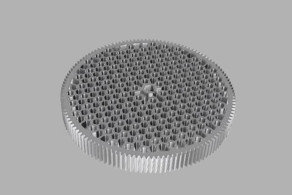
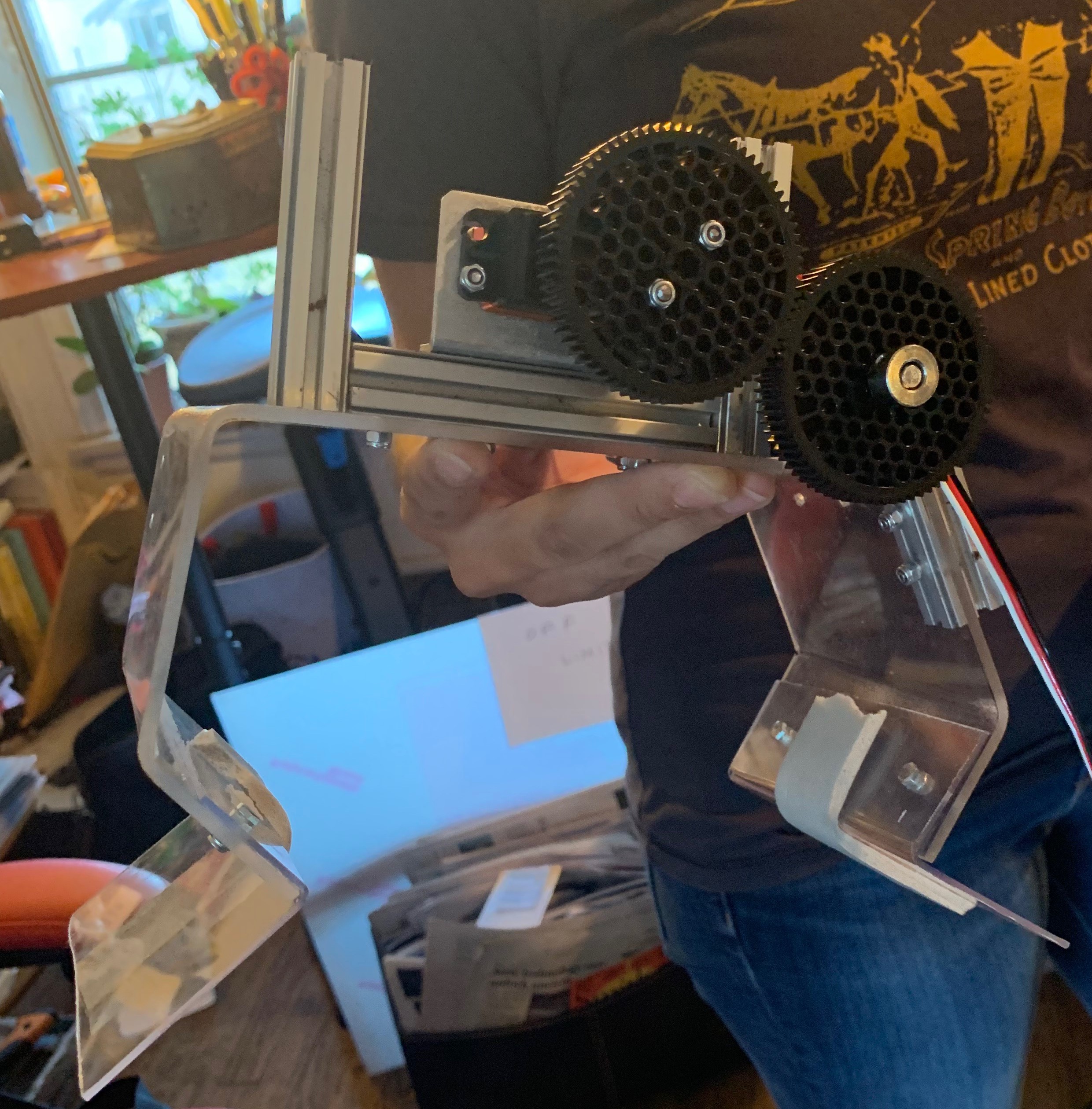
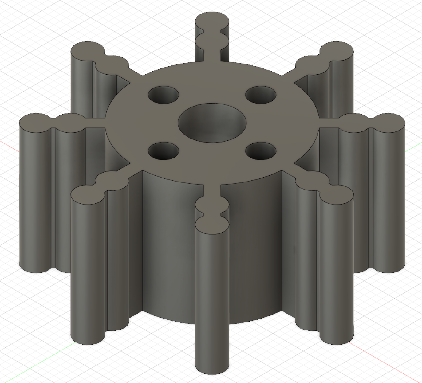
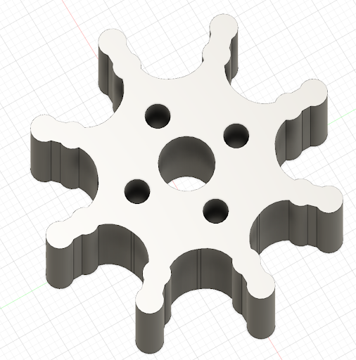
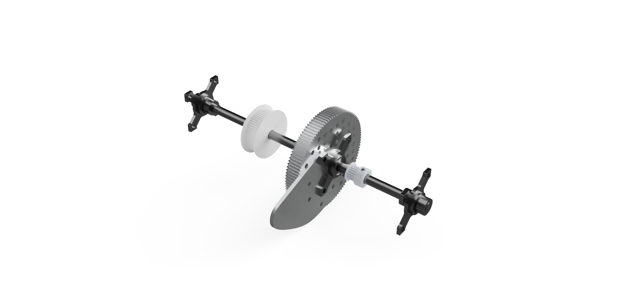
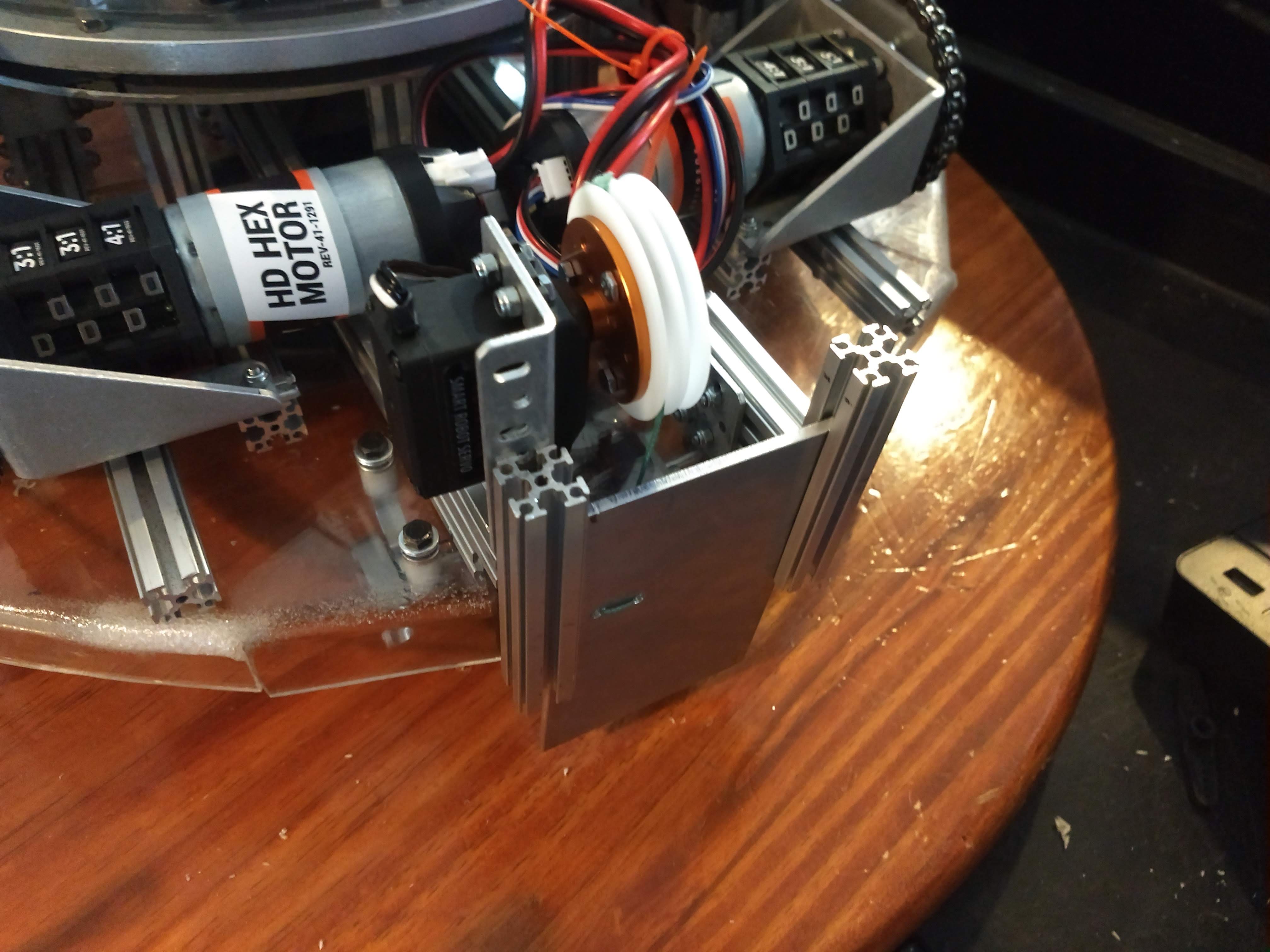
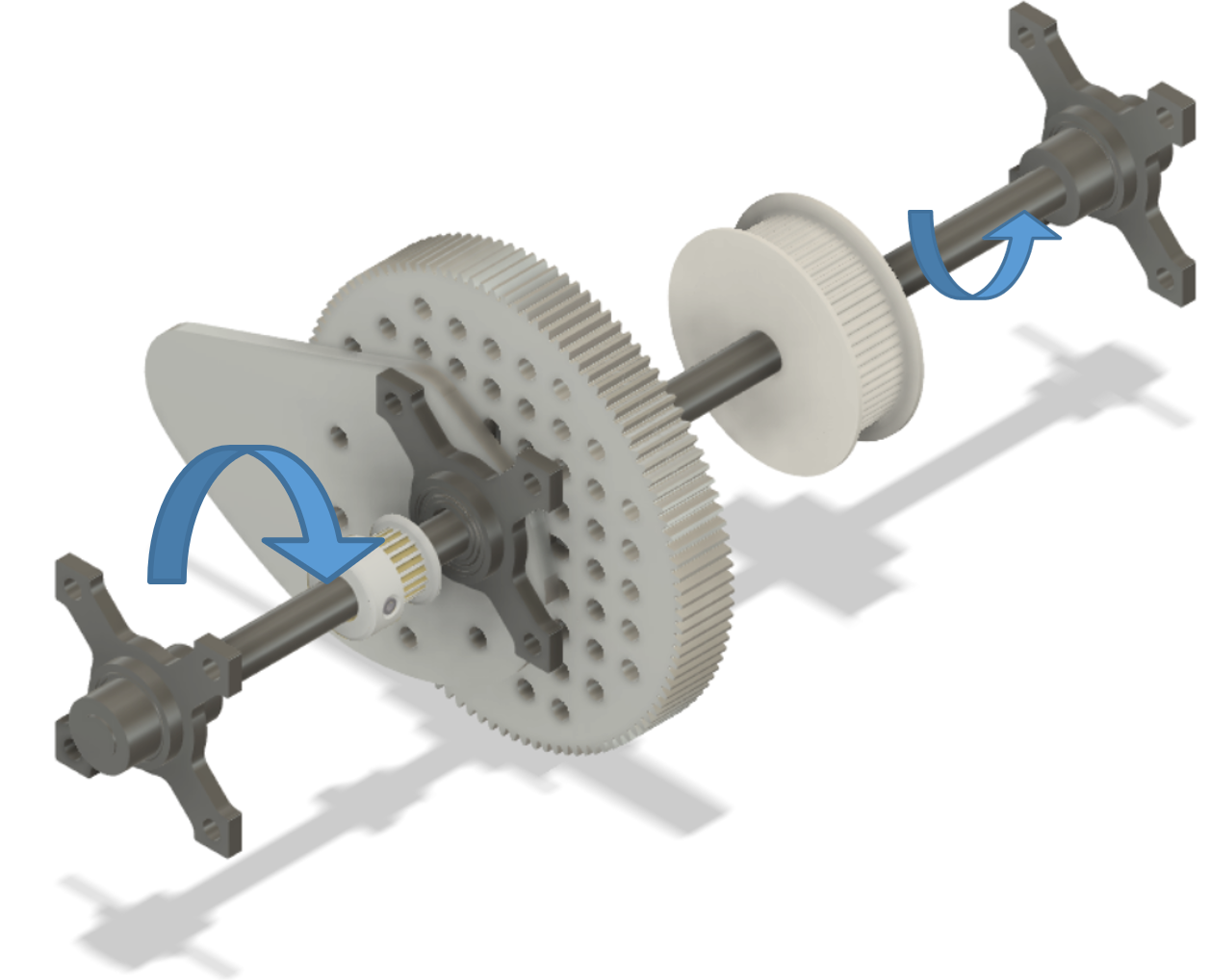
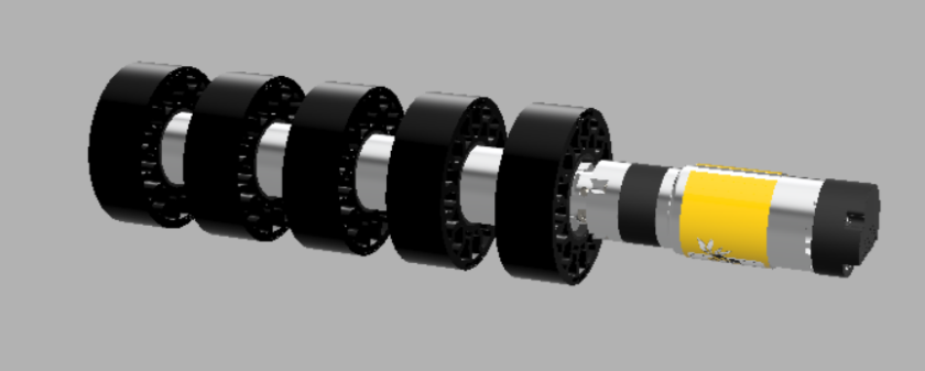
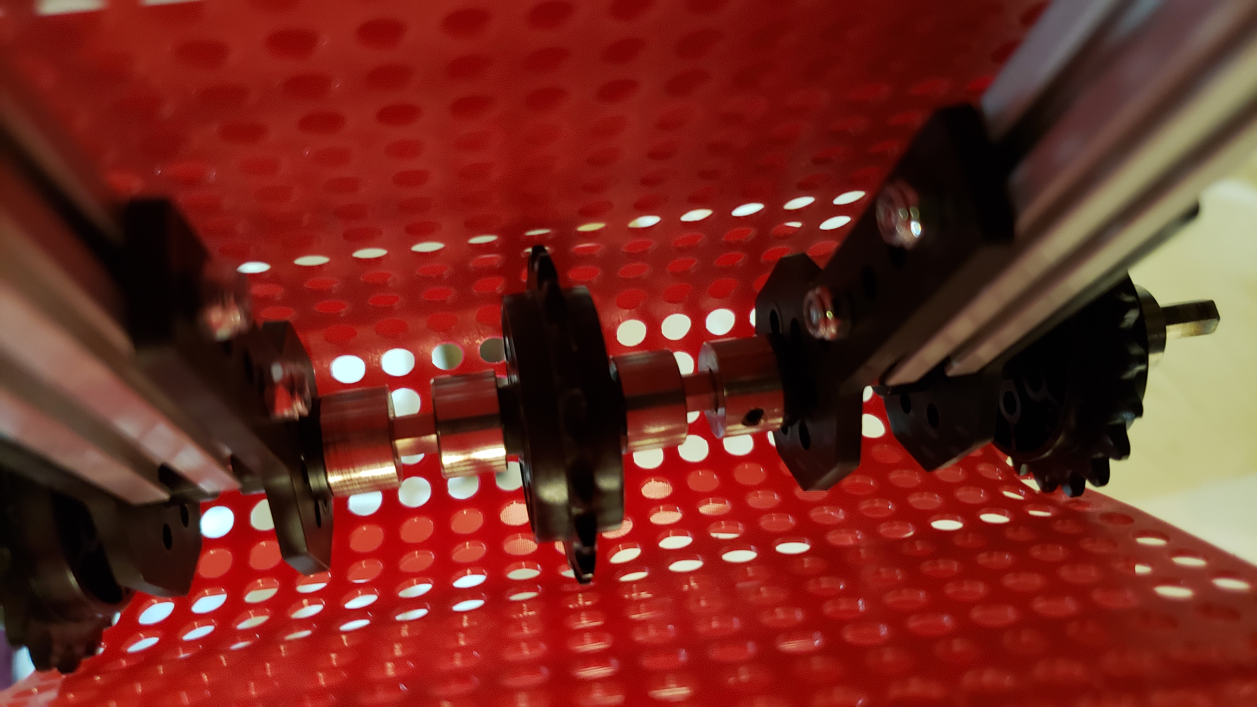
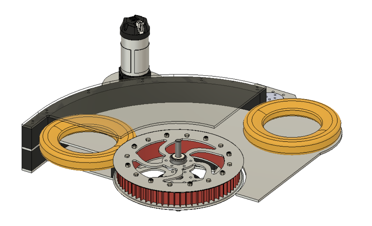
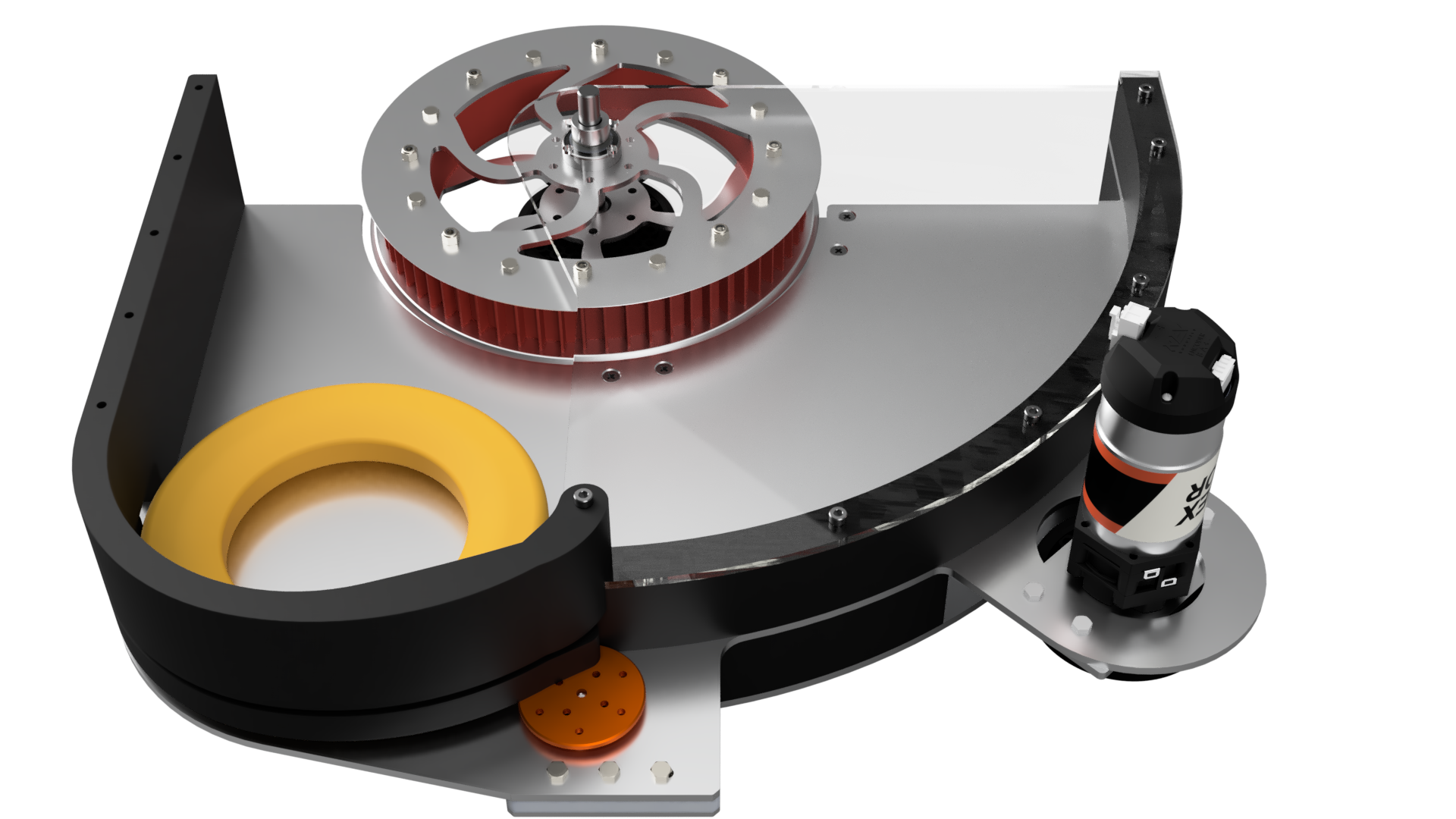
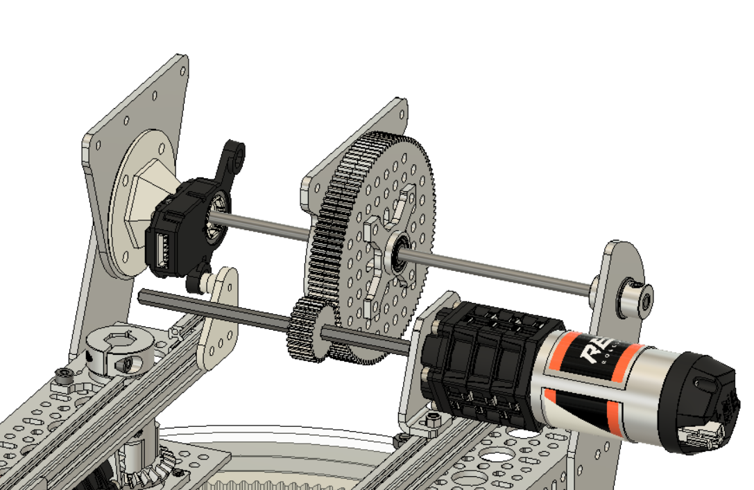
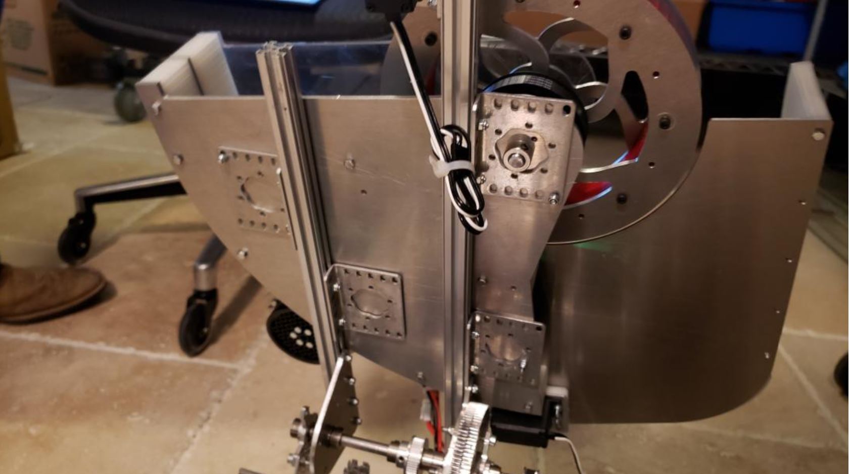
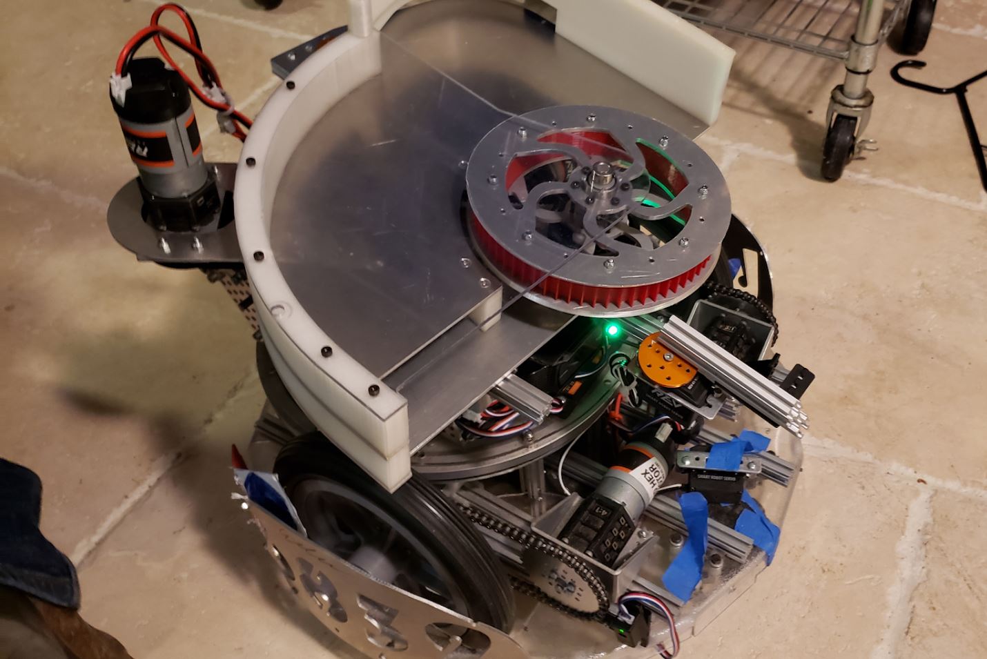
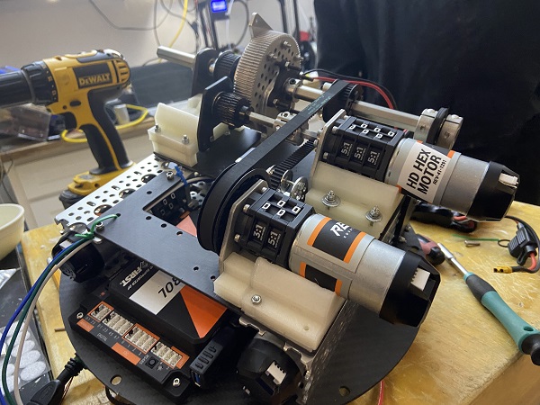
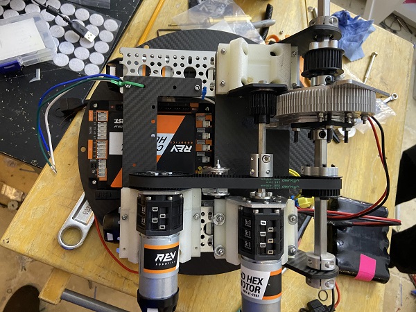
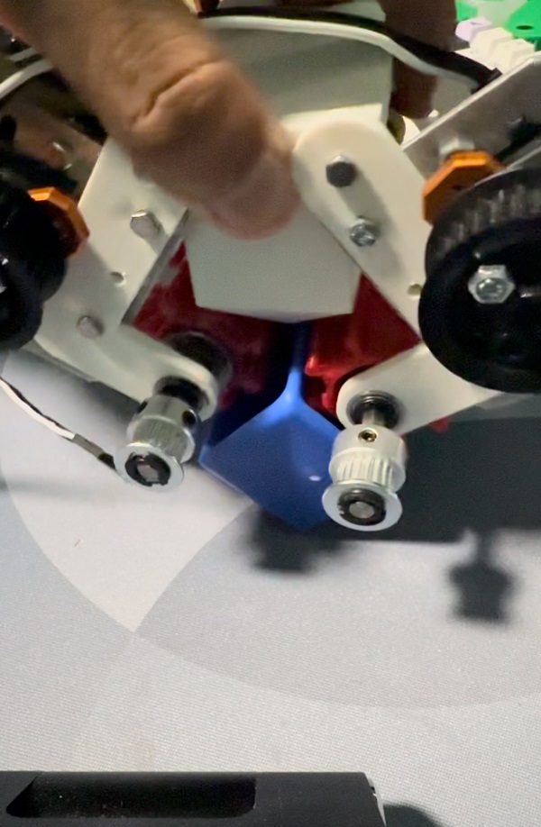
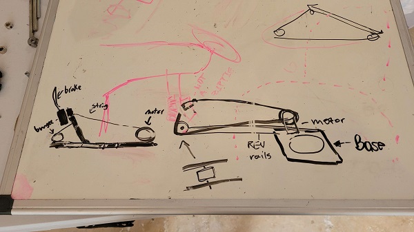
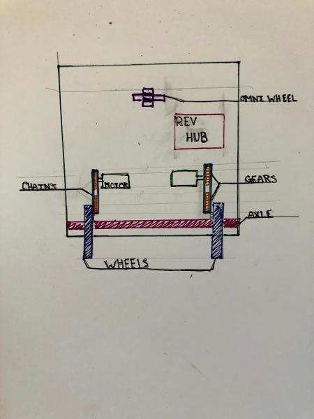
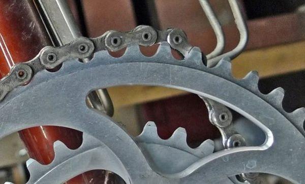
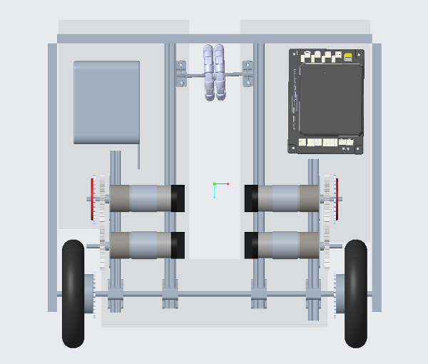
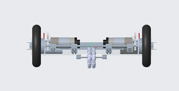
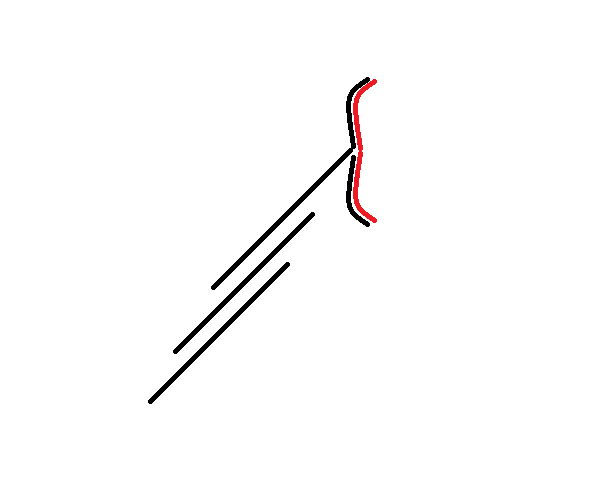
To lift the foot, we used heavy-duty twine that could withstand the forces put upon it. The twine was tied to the back of the foot and passed through an elevated pulley(allowing us to more effectively lift the foot through mechanical advantage) to a spool. We used a REV ultraplantery motor connect to a gear train to rotate the spool and lift the foot. Our usage of gears and an elevated pulley system allowed to to counteract the tension of the bungees and release the brake.
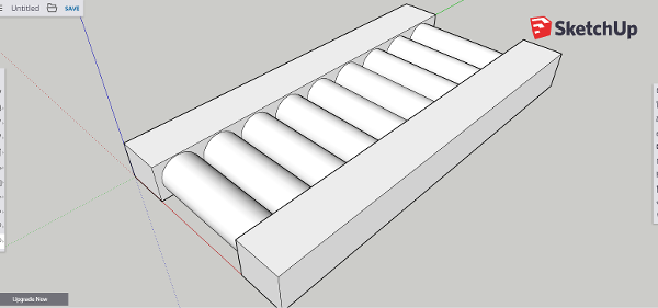
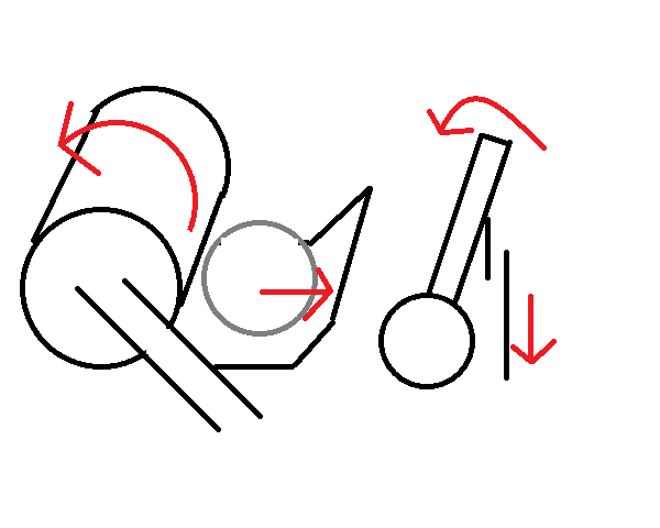
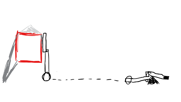
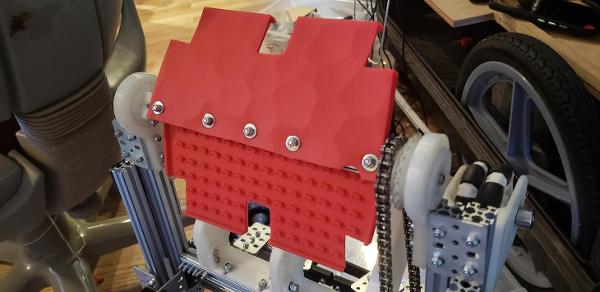
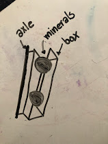
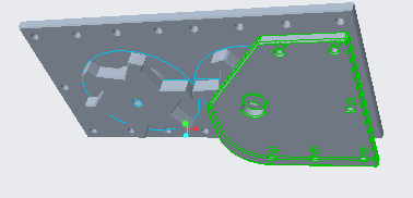
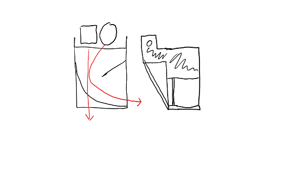
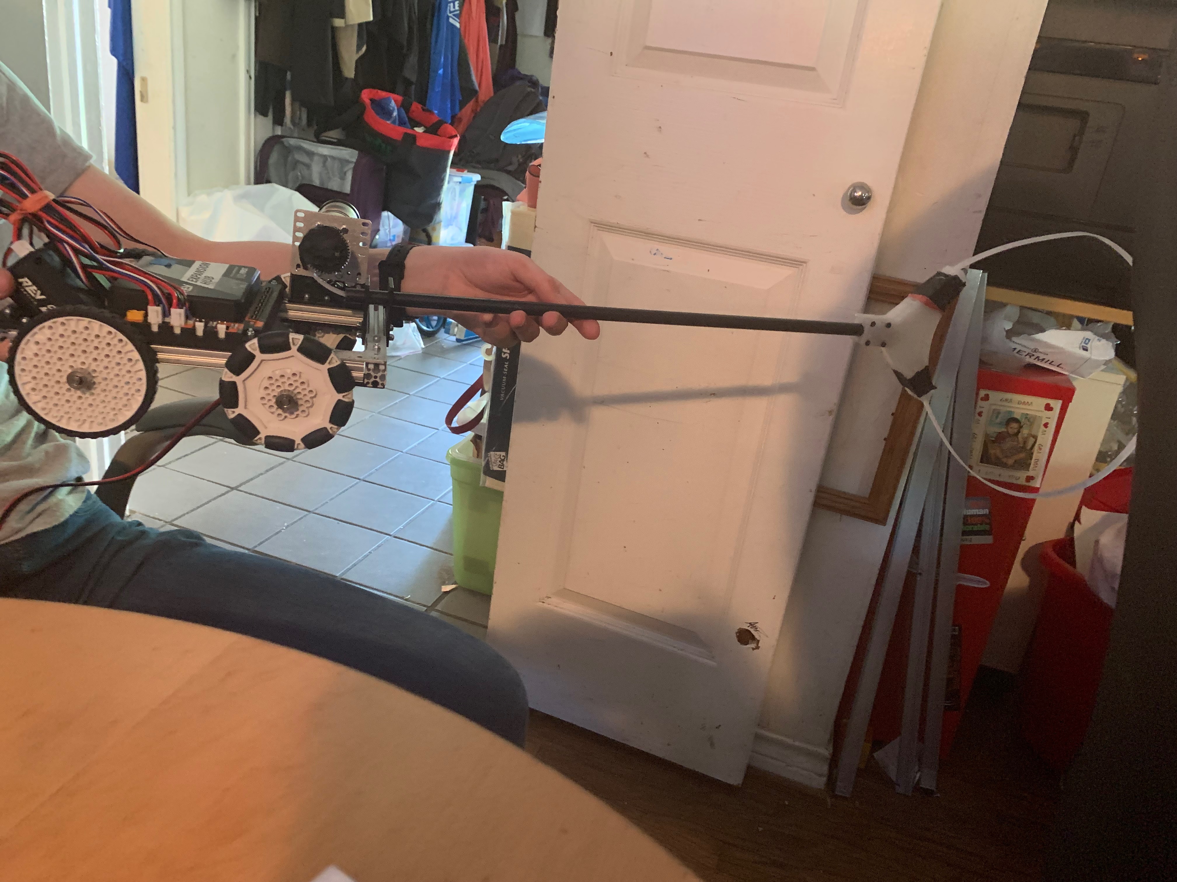
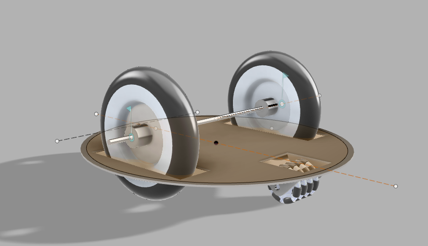
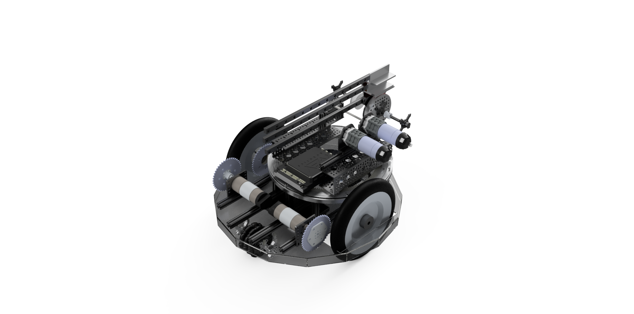
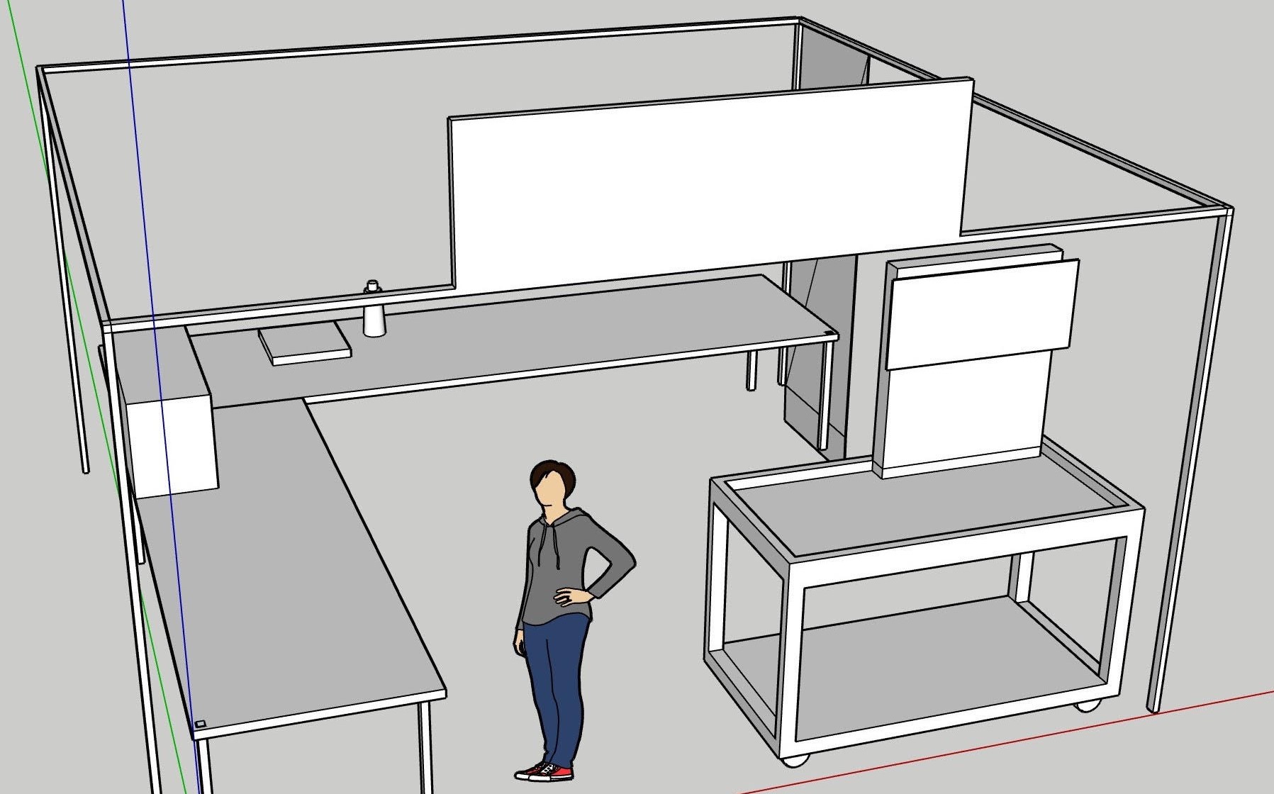
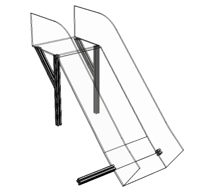
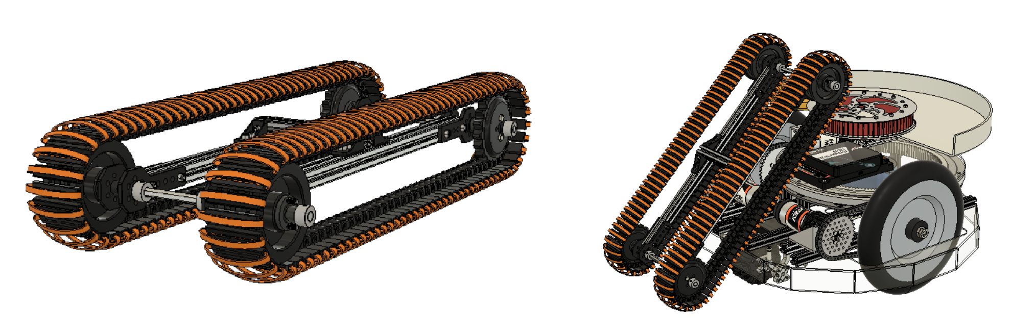
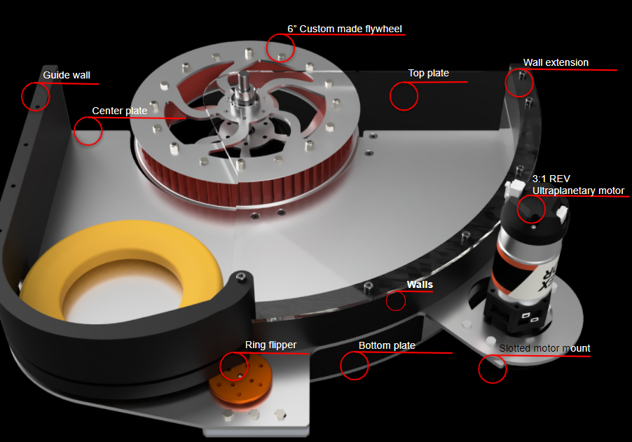
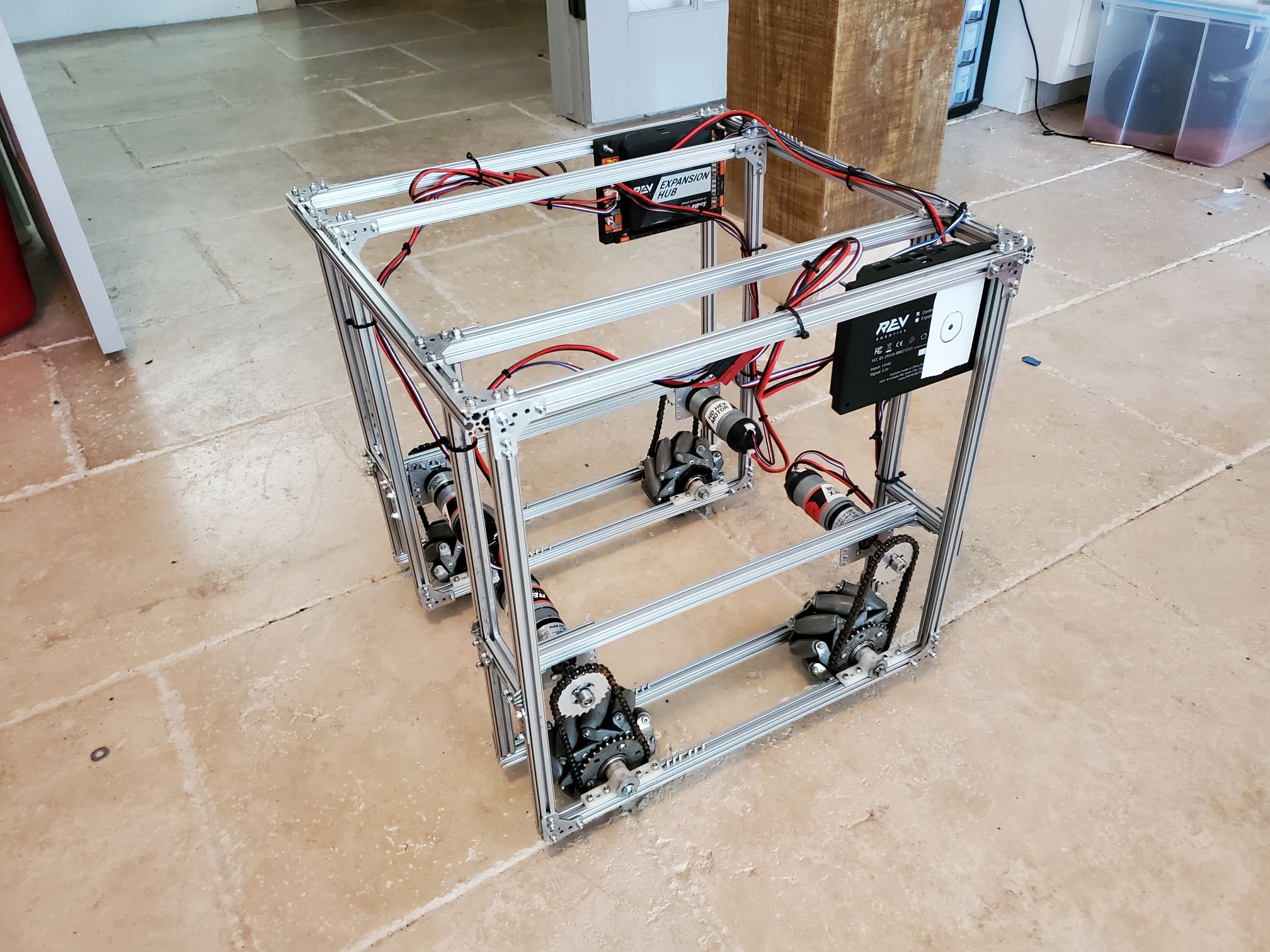
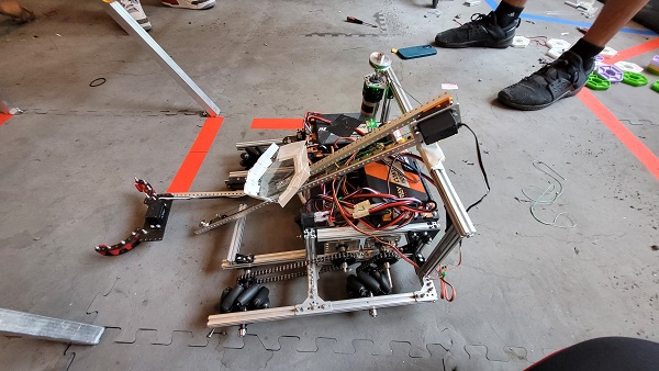
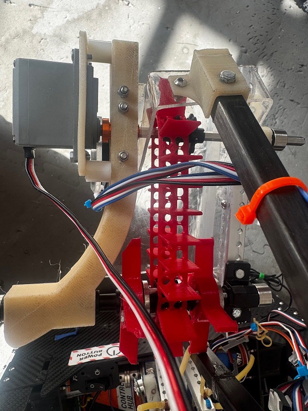
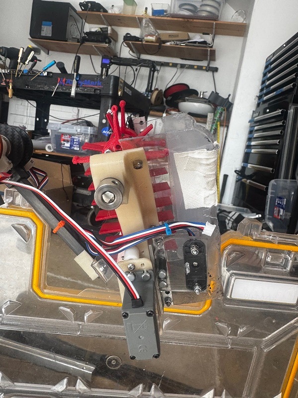
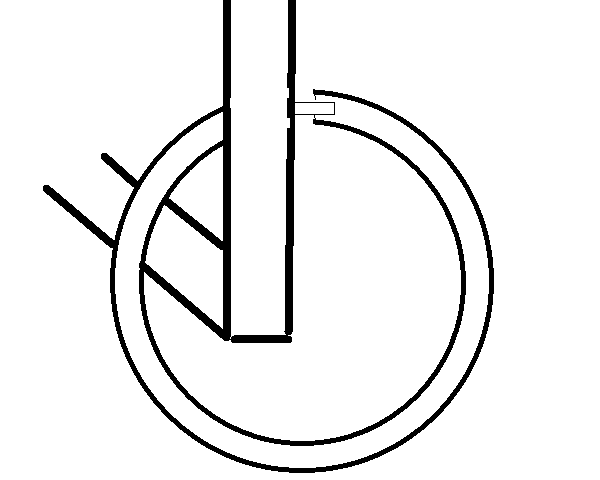
The diagram below highlights the major components of the system as described above.
Coding
The code for the “unbreaking” mechanism consists of two parts: calibration and running. Additionally for the code of the robot we refer to the braking system as the unbreak as it only runs when we want to stop breaking.
First we perform the calibration where we run the motor until we have tightened the string pulling the unbreak up and we set this encoder position to 0 and are not able to go lower then this. Then we run the break until a human sees that the break has stopped being depressed; this is the maximum for the unbreak, and we cannot go higher than that. That finishes the calibration sequence now we can run the unbreak.
The way that the unbreak runs is a two-fold controller system. One person must depress the deadman switch or the unbreak will automatically run to its lowest position. Once the deadman switch is depressed then the unbreak can be lifted. When the trigger to unbreak is pressed when the deadman switch is active then the unbreak will raise until it reaches its max or until the trigger is released. When the trigger is released the unbreak runs back down to ensure that we are always breaking when not actively unbreaking.
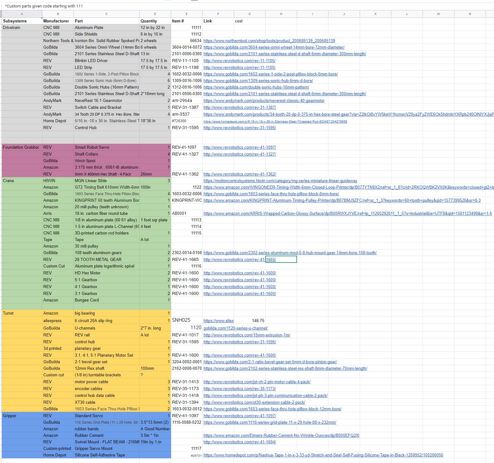
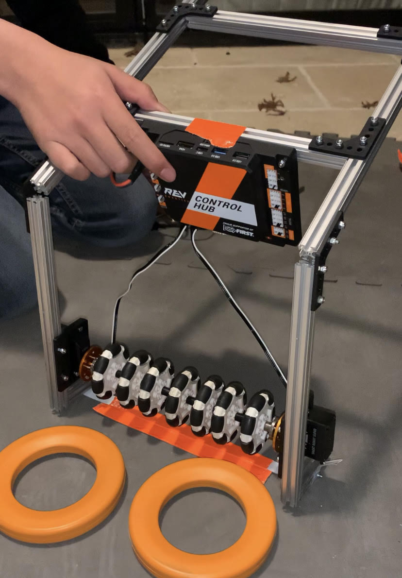
A majority of the system is comprised of REV parts, illustraring how we can use the parts on our FTC robots for larger and more complex applications. The system itself, after lots of code tuning, worked pretty reliability throughout our testing.
Next Steps
We are hoping to further test R2V2 and extend upon its capabilities and further share our progress through our blog, socials, and Youtube.

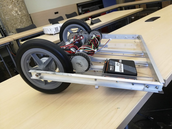
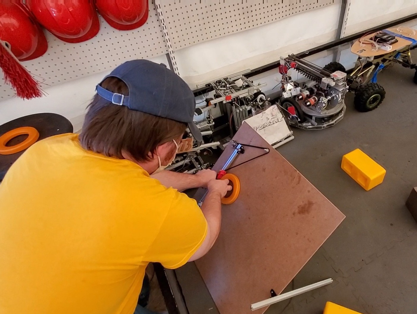
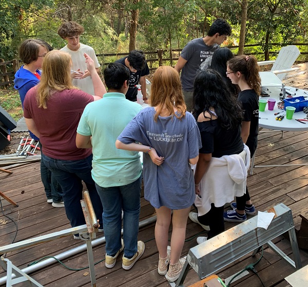
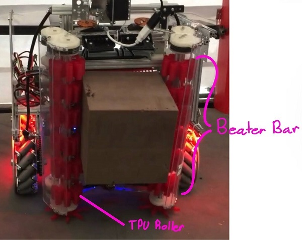
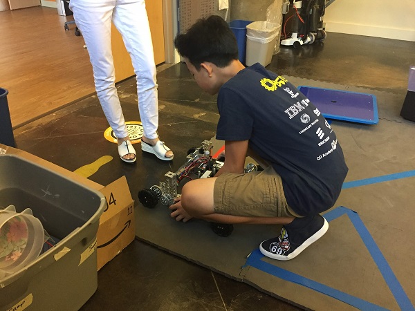 Austin Lui of Technicbots gets their chassis ready for testing.
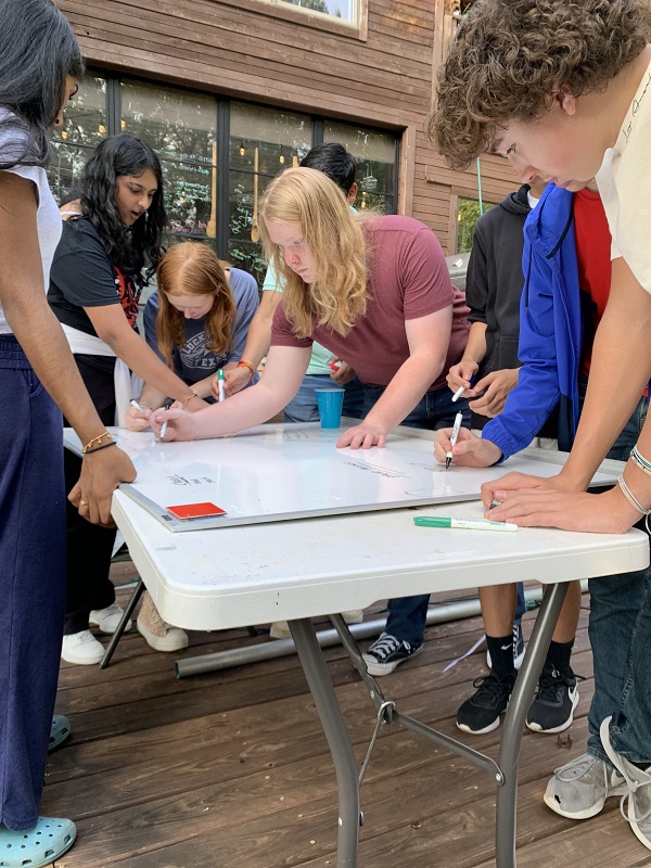
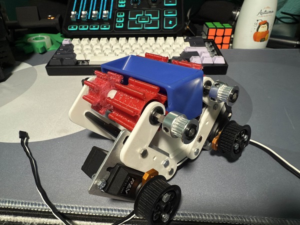
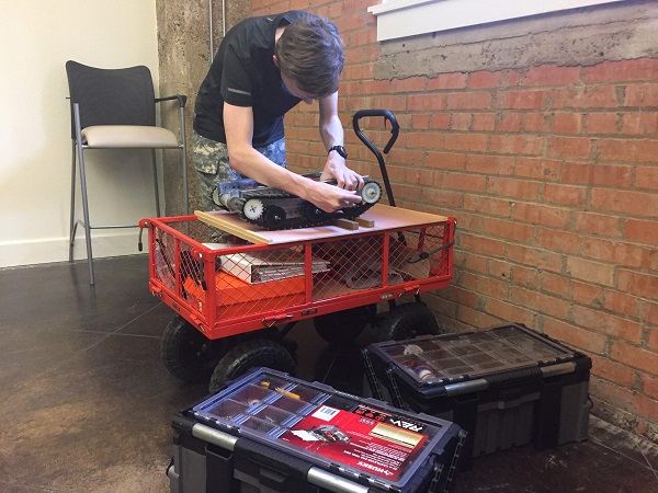 Connor Mihelic of EFFoRT adds some finishing touches.


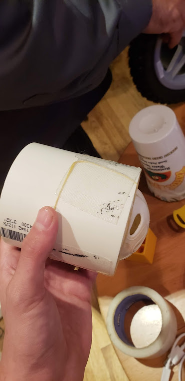
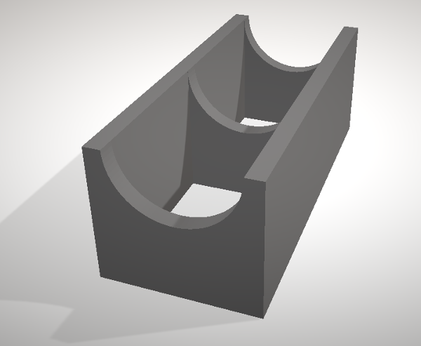
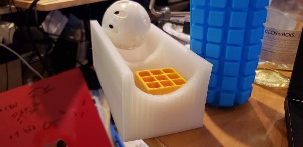
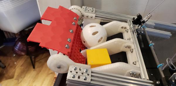
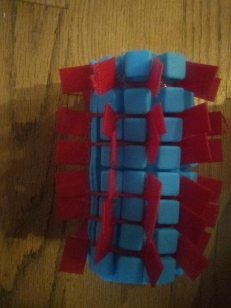
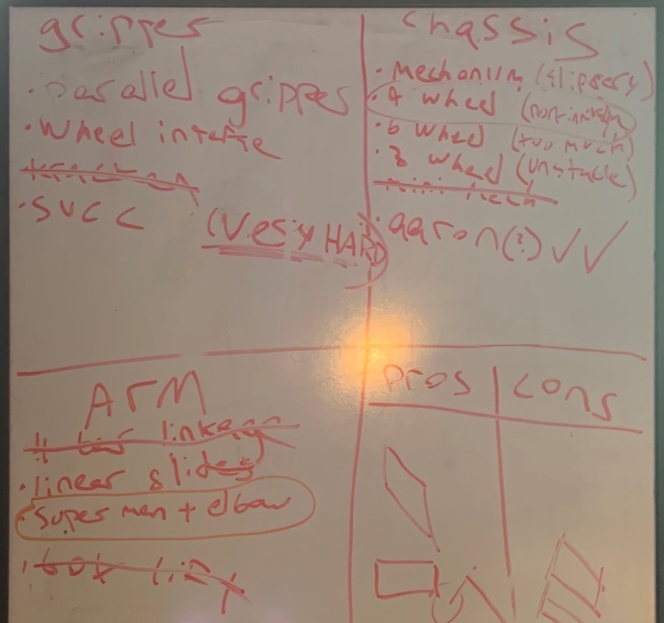
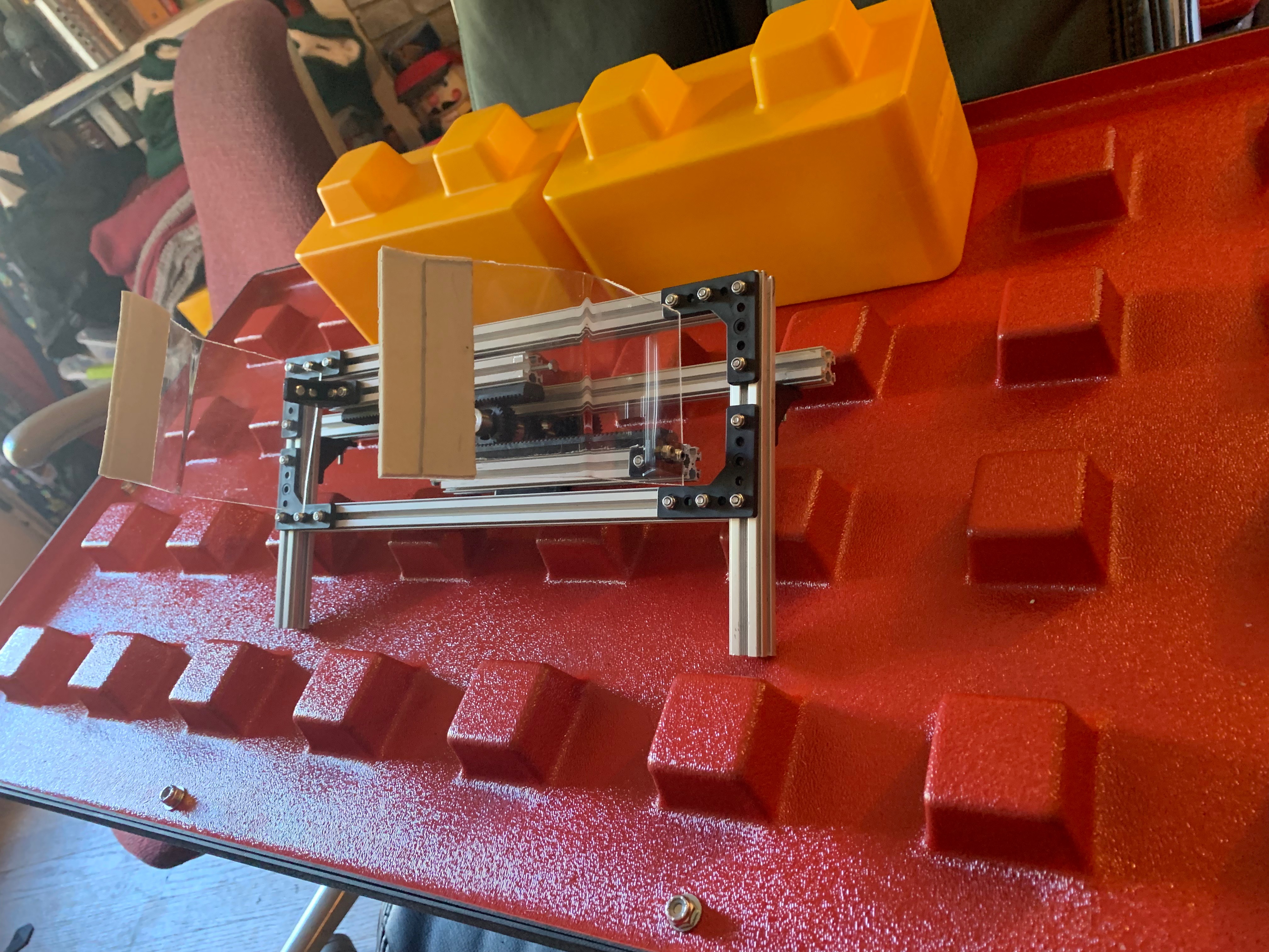
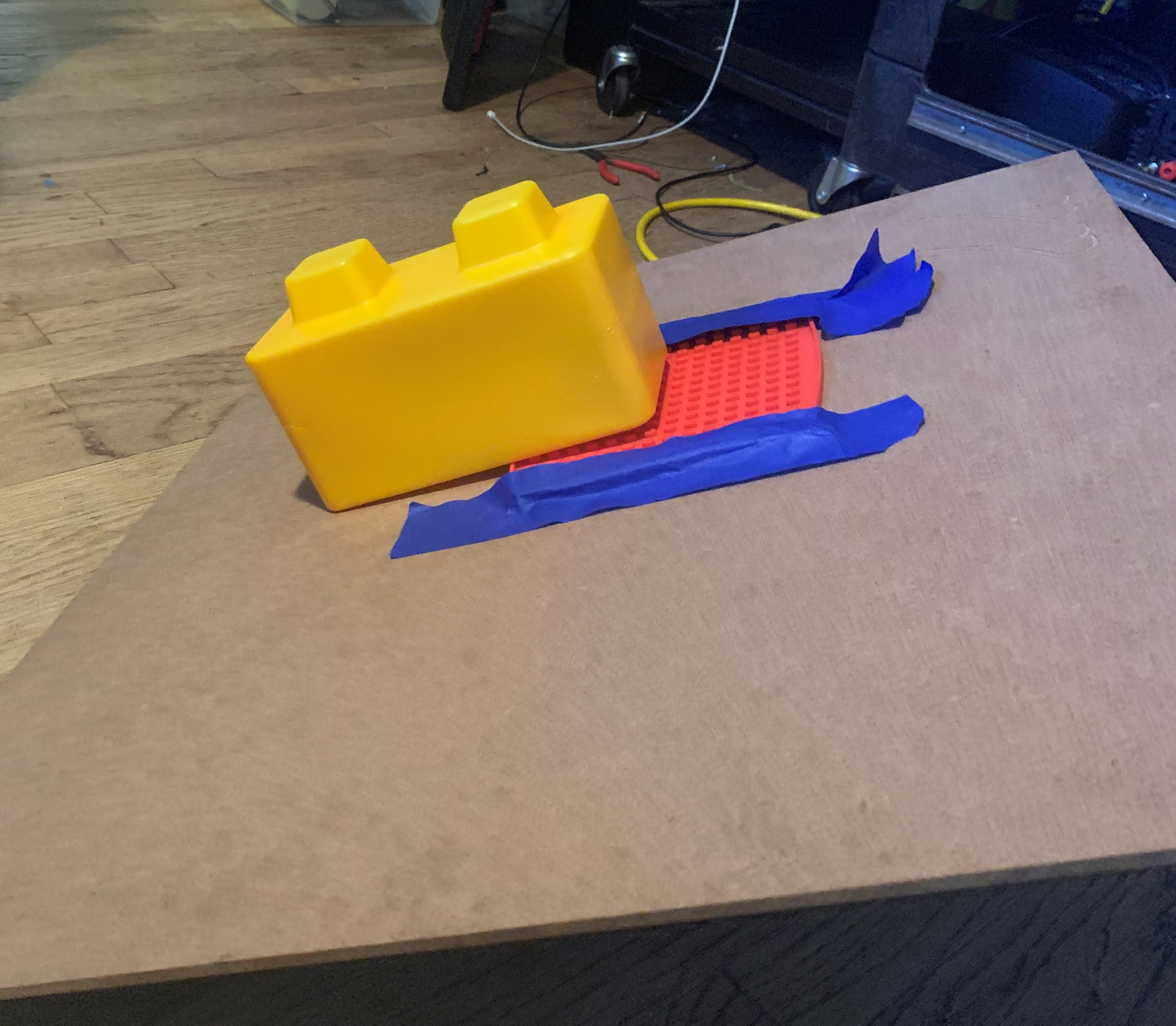
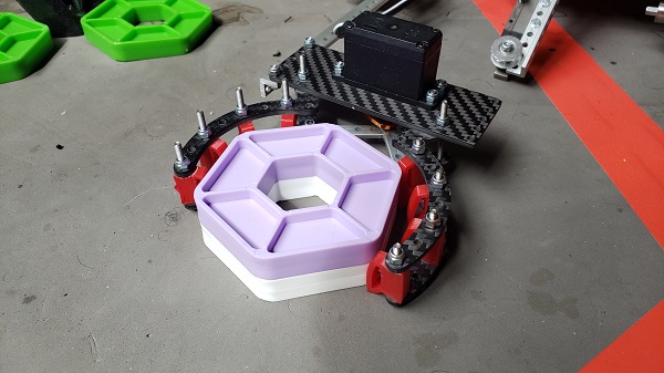
 This suggestion uses a plastic flap to "trap" game elements inside it, similar to the lid of a soda cup. You can put marbles through the straw-hole, but you can't easily get them back out.
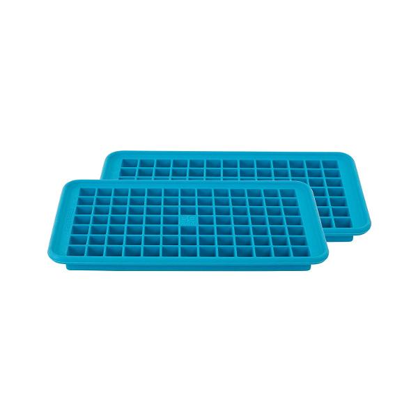
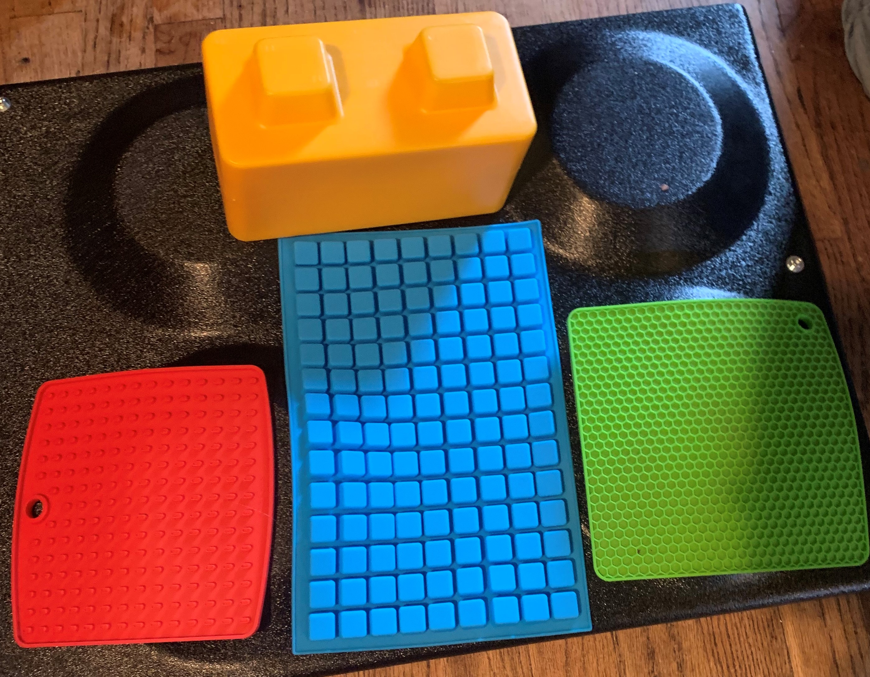
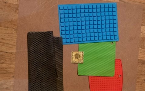
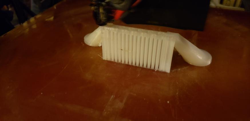
 This one is simple - a linear slide arm attached to a motor so that it can pick up game elements and rotate. We fear, however, that many teams will adopt this strategy, so we probably won't do it. One unique part of our design would be the silicone grips, so that the "claws" can firmly grasp the silver and gold.
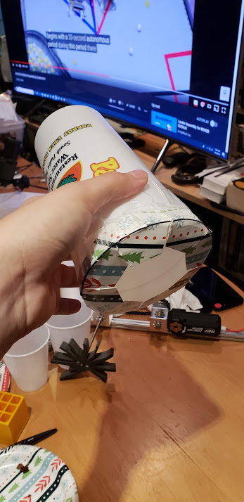
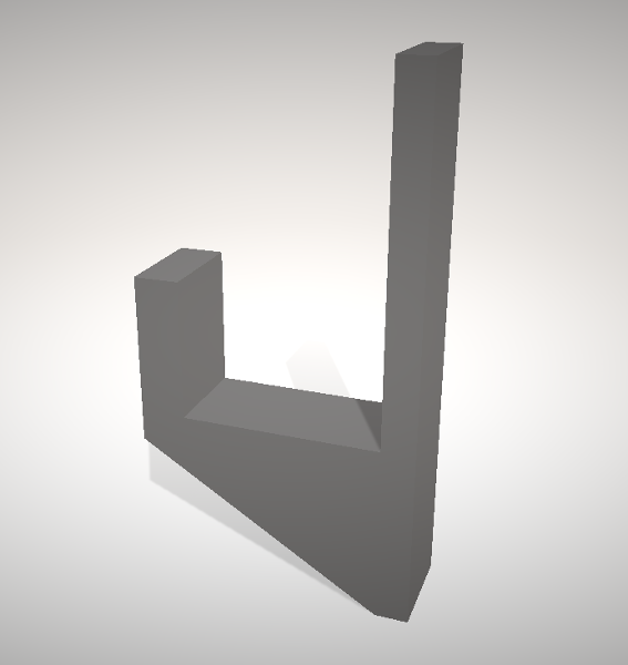
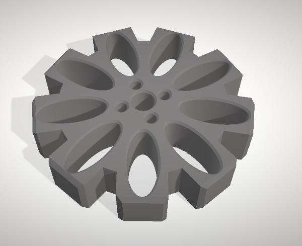
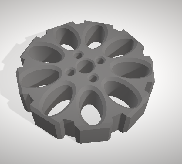
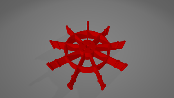
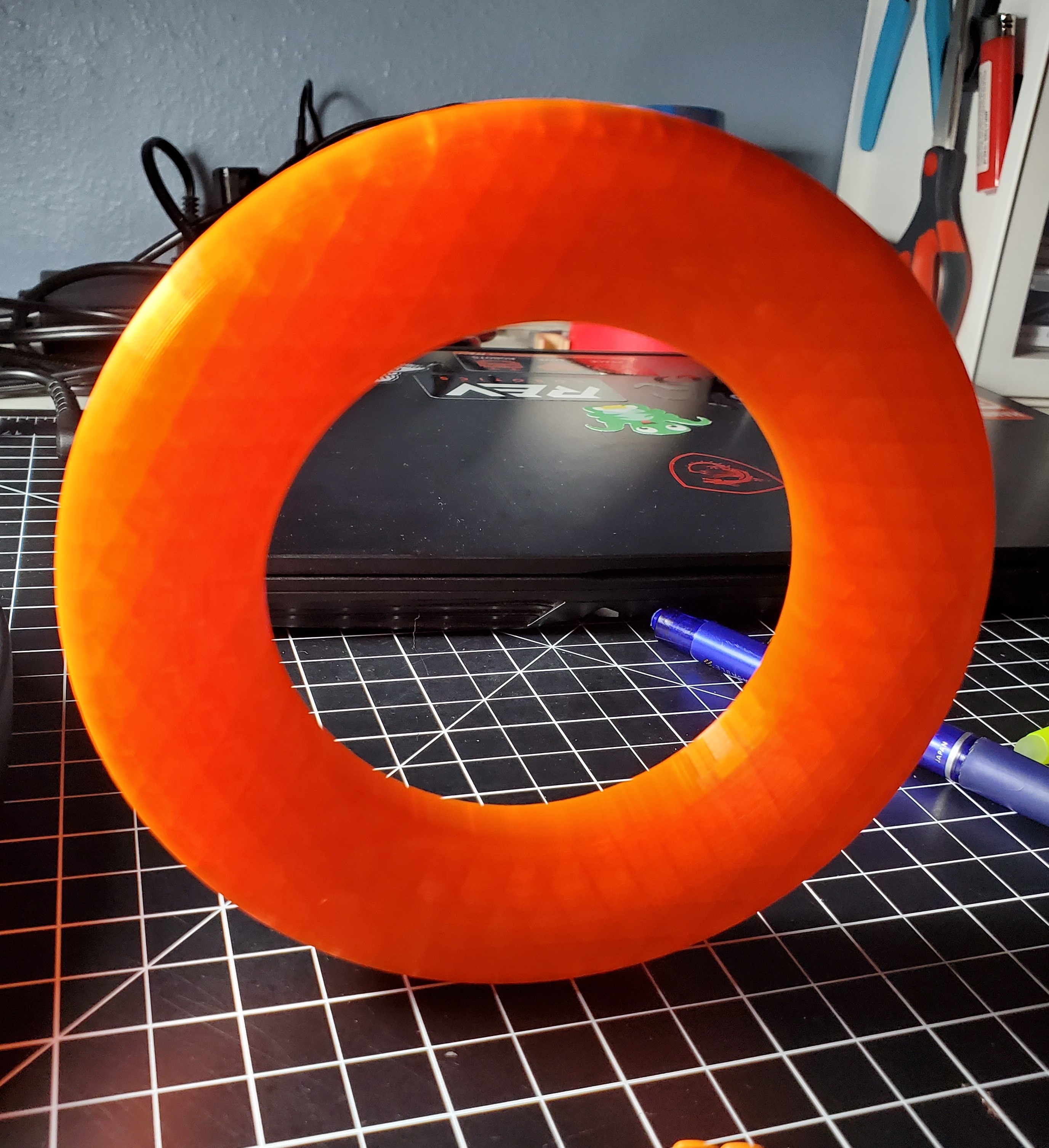
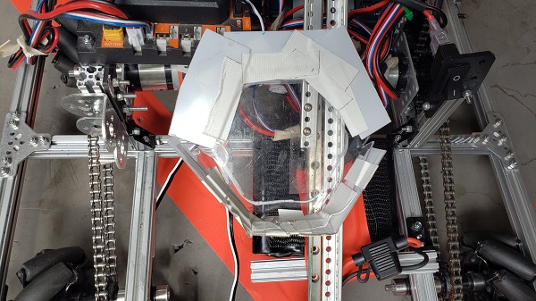
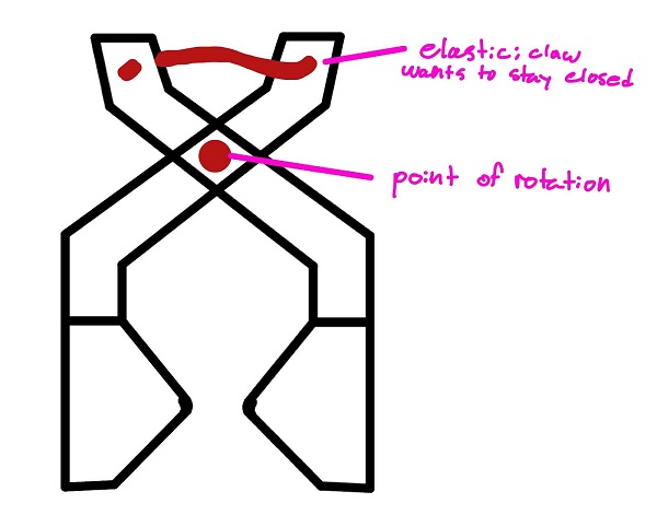
 When we did Res-Q, we dropped our robot more times than we'd like to admit. To prevent that, we're designing an interlocking mechanism that the robot can use to hang. It'll have an indent and a corresponding recess that resists lateral force by nature of the indent, but can be opened easily.