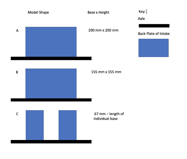
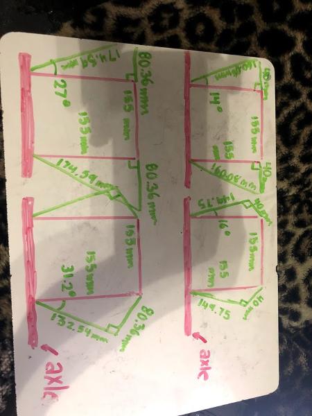
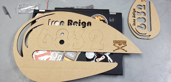
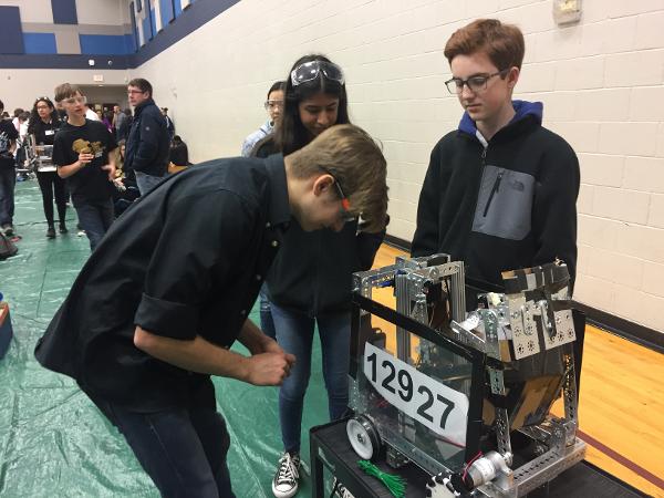
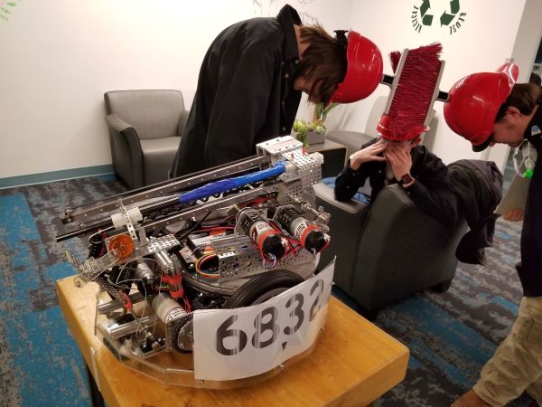
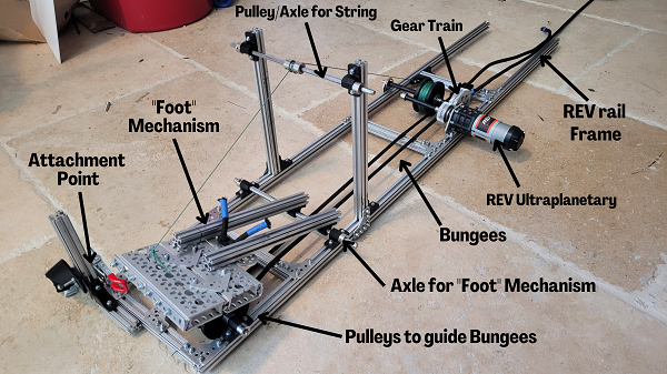
UIL and State Play-by-Play
By Aarav, Anuhya, Jai, Alex, Tanvi, Georgia, Gabriel, Trey, Vance, Leo, Arun, and Krish
Review the events of the UIL and FTC State Championships
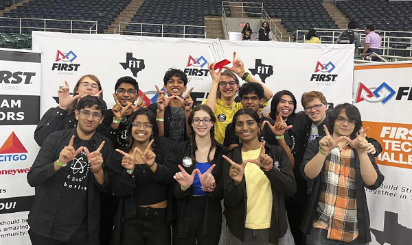
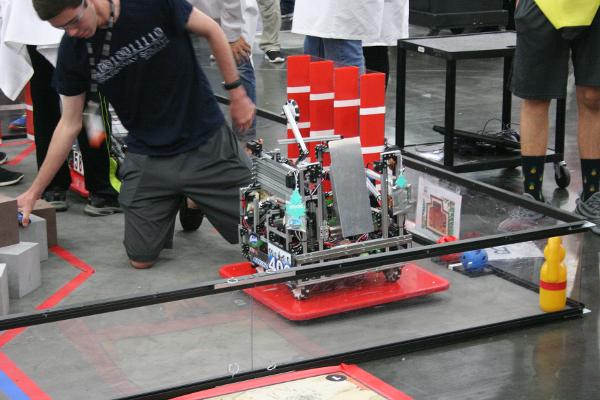
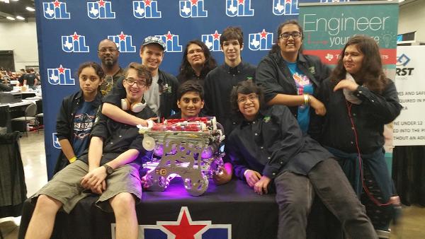
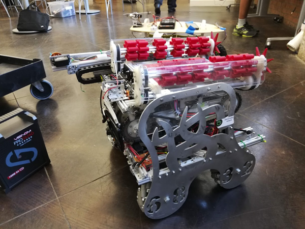
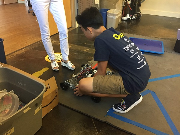
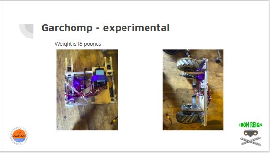
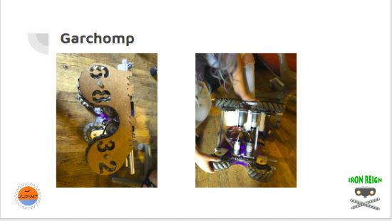
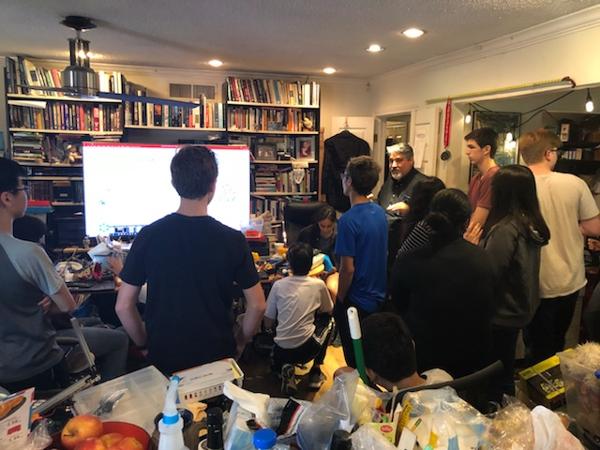
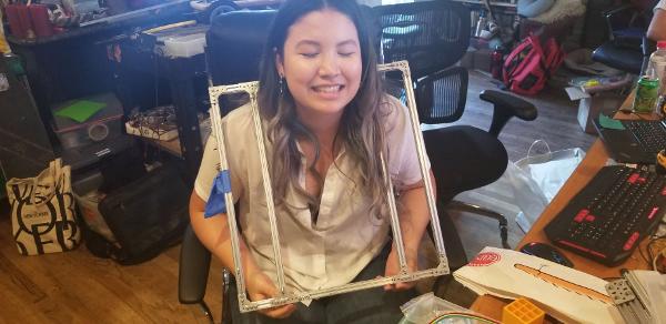
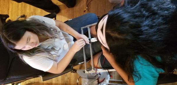
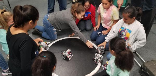
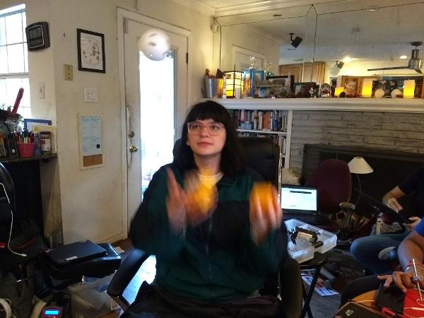
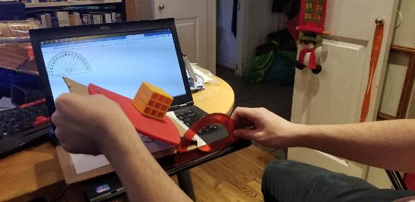
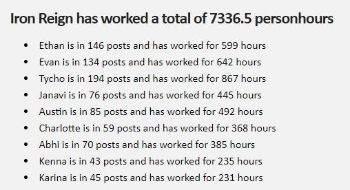
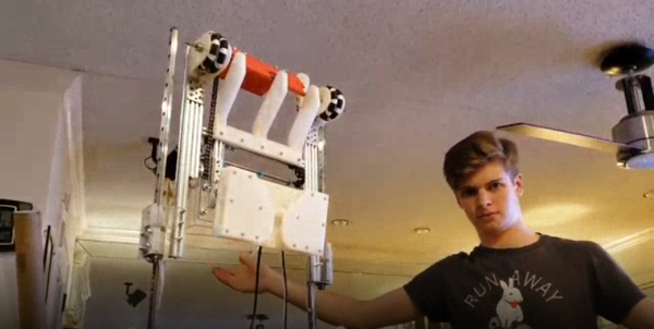
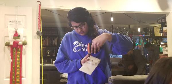
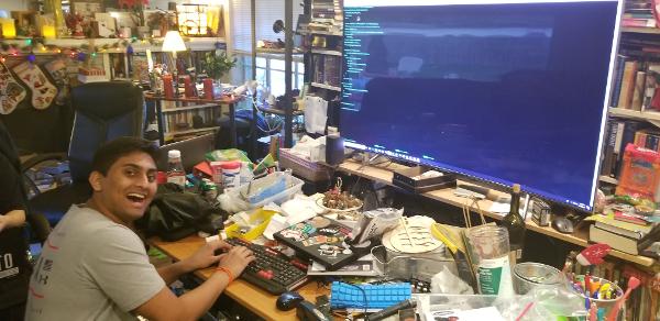
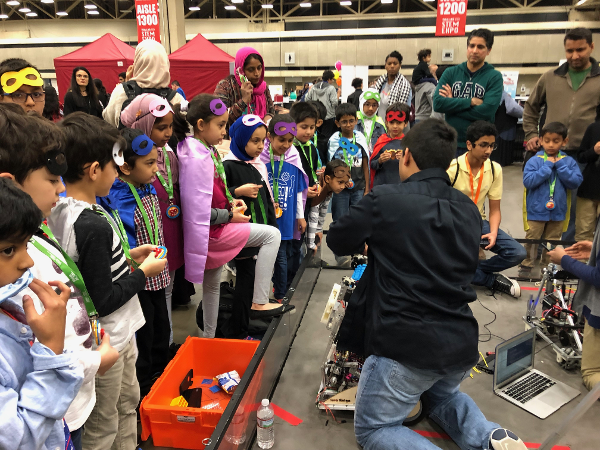
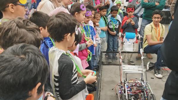
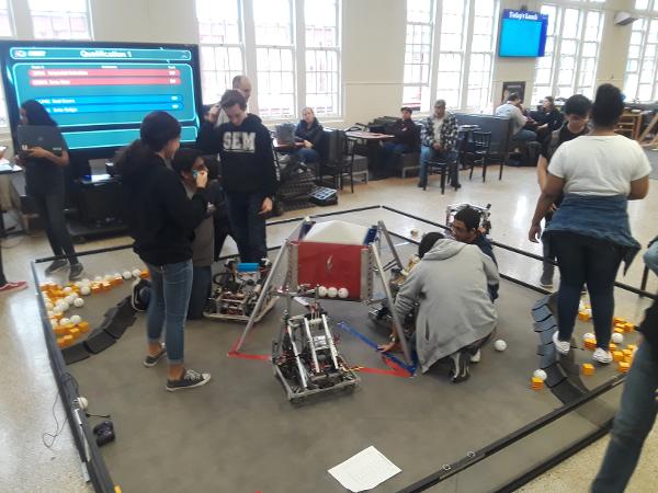
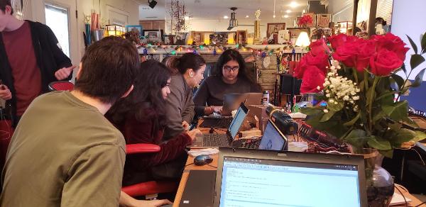
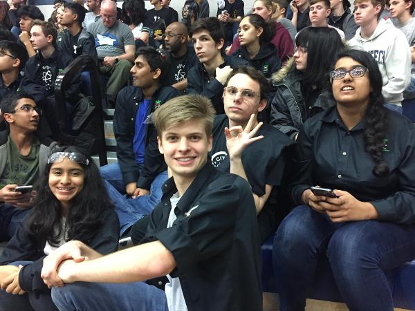
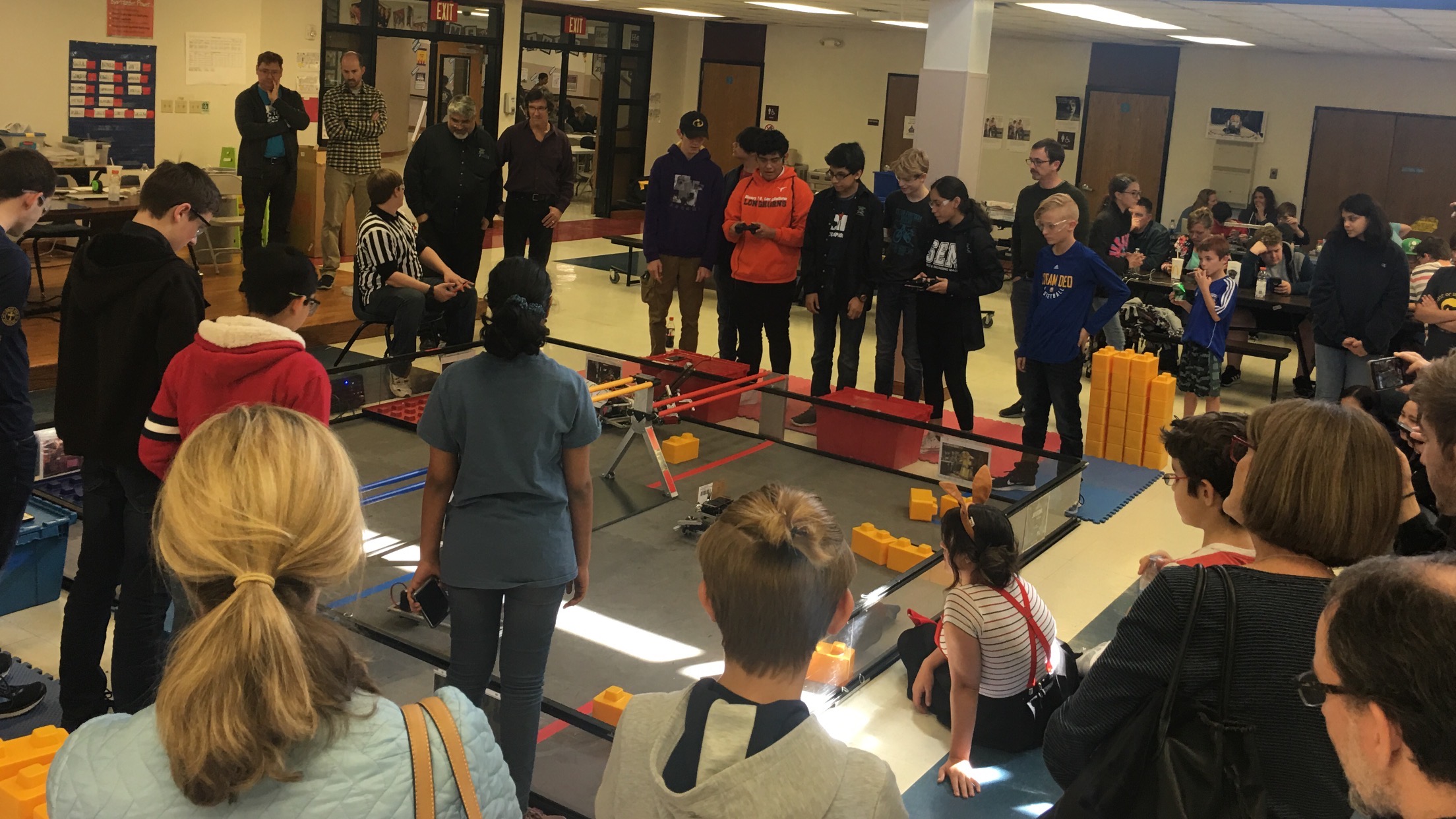
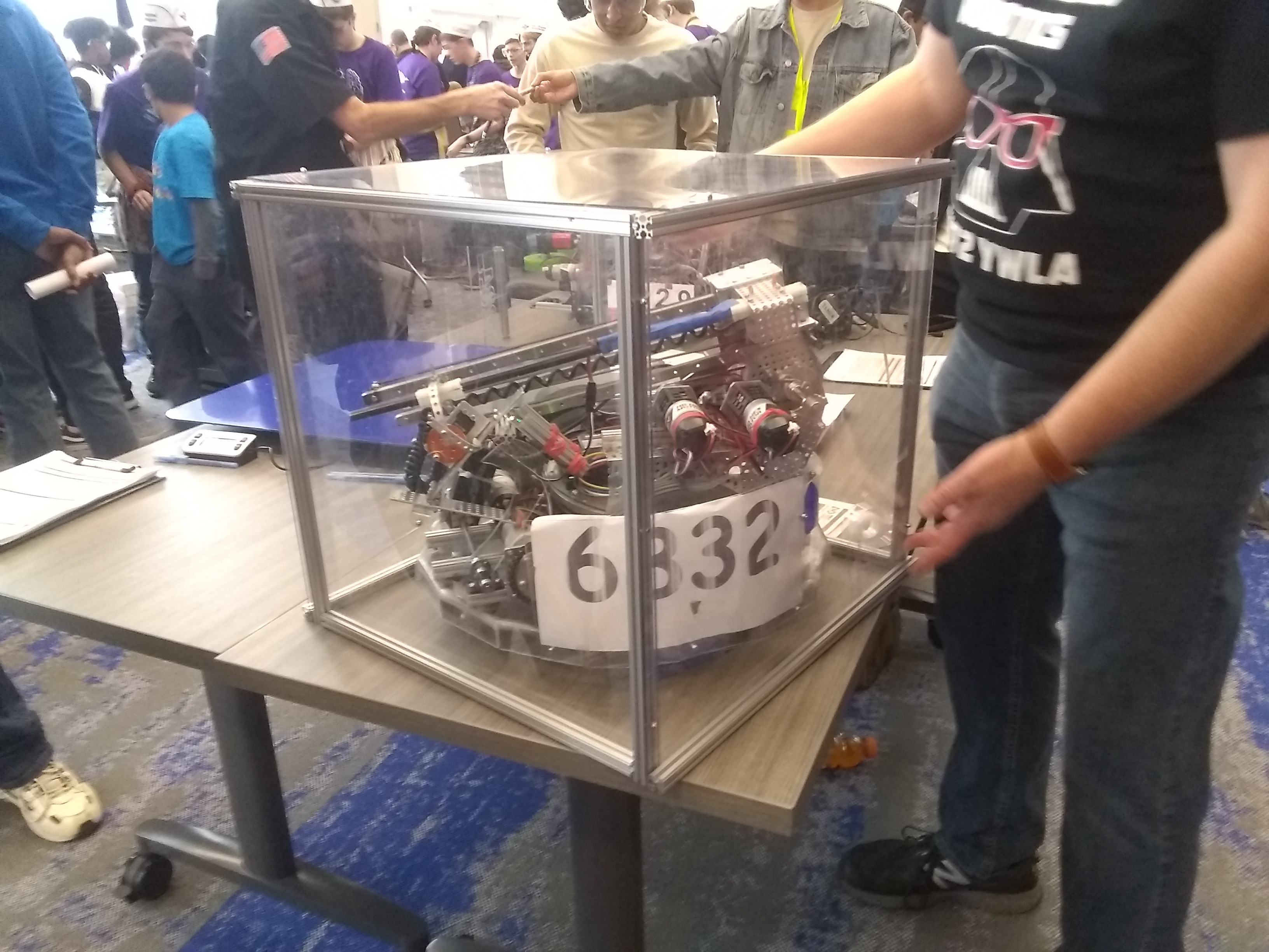
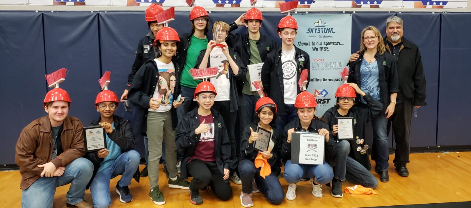
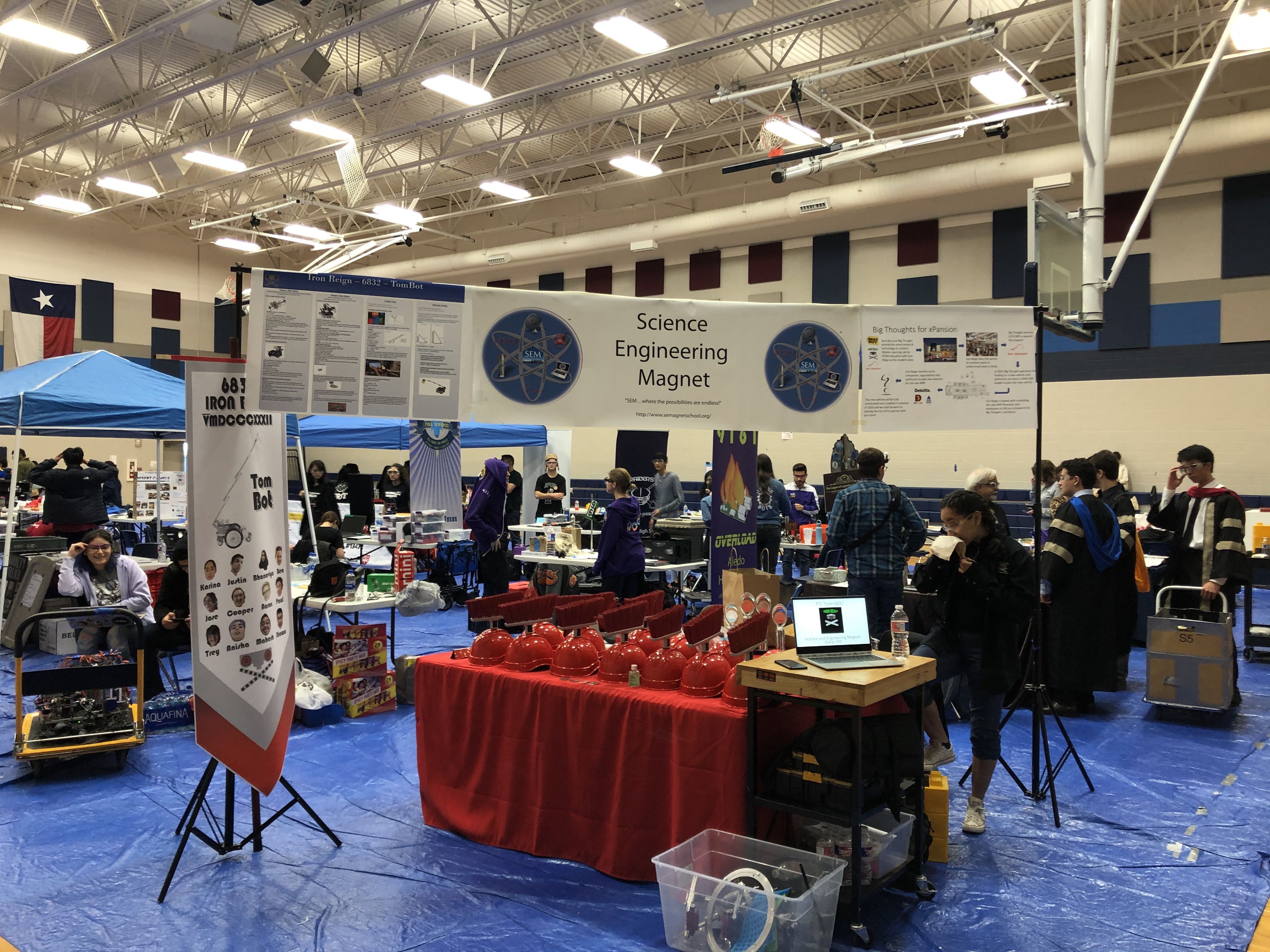
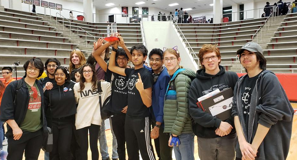
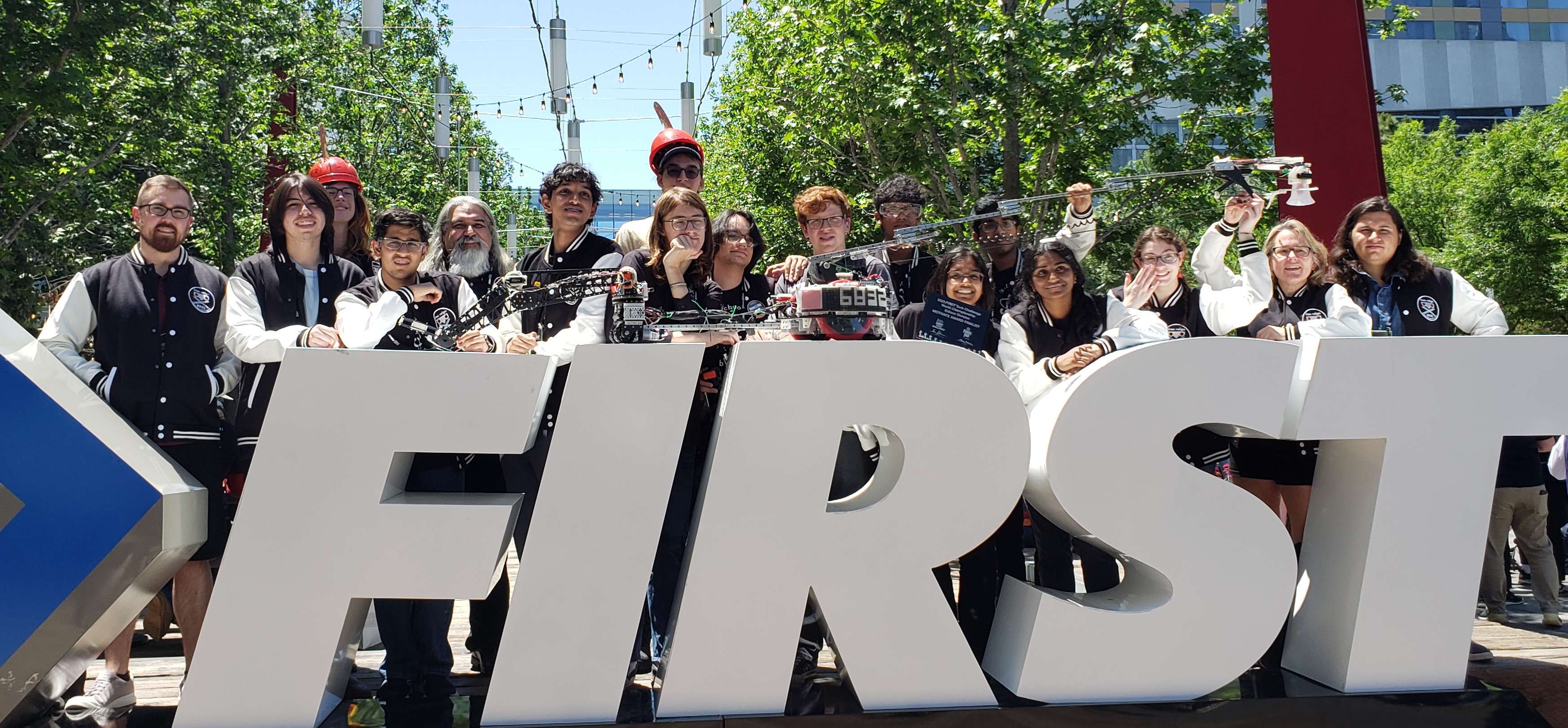
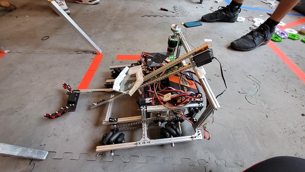
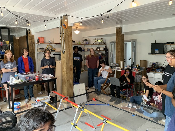
This past week we participated in the FTC state championship and UIL state competition in Belton, Texas. Overall, we were successful, winning the Think Award at State and thus advancing to Worlds despite less-than-ideal robot performance. First, we will discuss judging and then transition into our game-by-game account. There will also be a post-mortem that will be uploaded later.
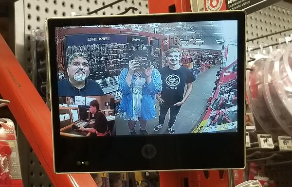
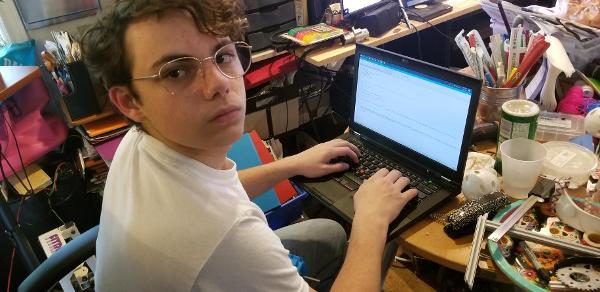
Regarding judging, all of it was done the week before the competition remotely. This meant we had to ensure that we remained on schedule because robot demonstrations are essential to virtual judging. Unfortunately, we could not show a live transfer, but we did have embedded videos depicting our robot’s functionality. Our main presentation and callbacks went well despite a few mishaps, especially regarding the key points we wanted to hit. Overall though, we were able to show our innovation and iteration processes and how TauBot connected with our game strategy and our team’s story as a whole.
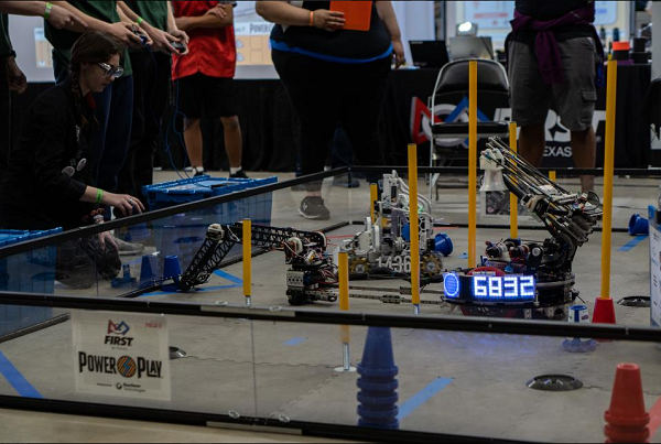
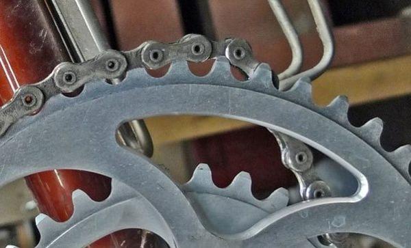
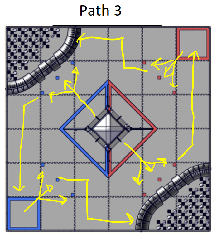
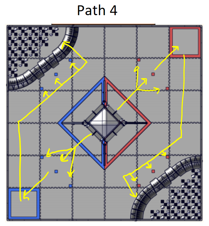
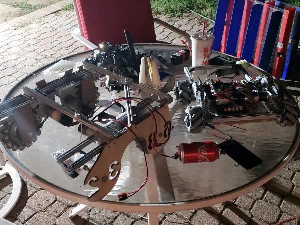
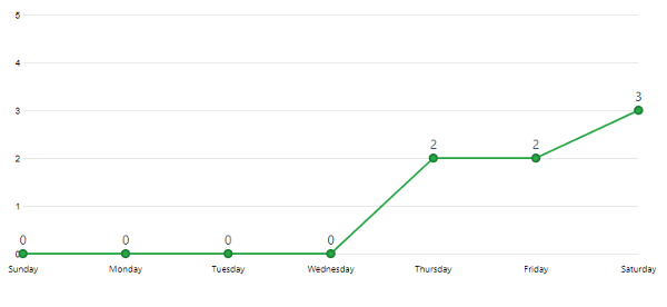
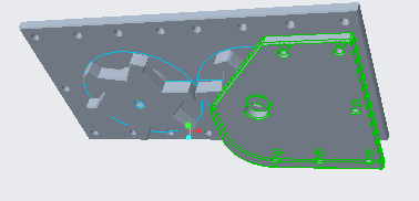
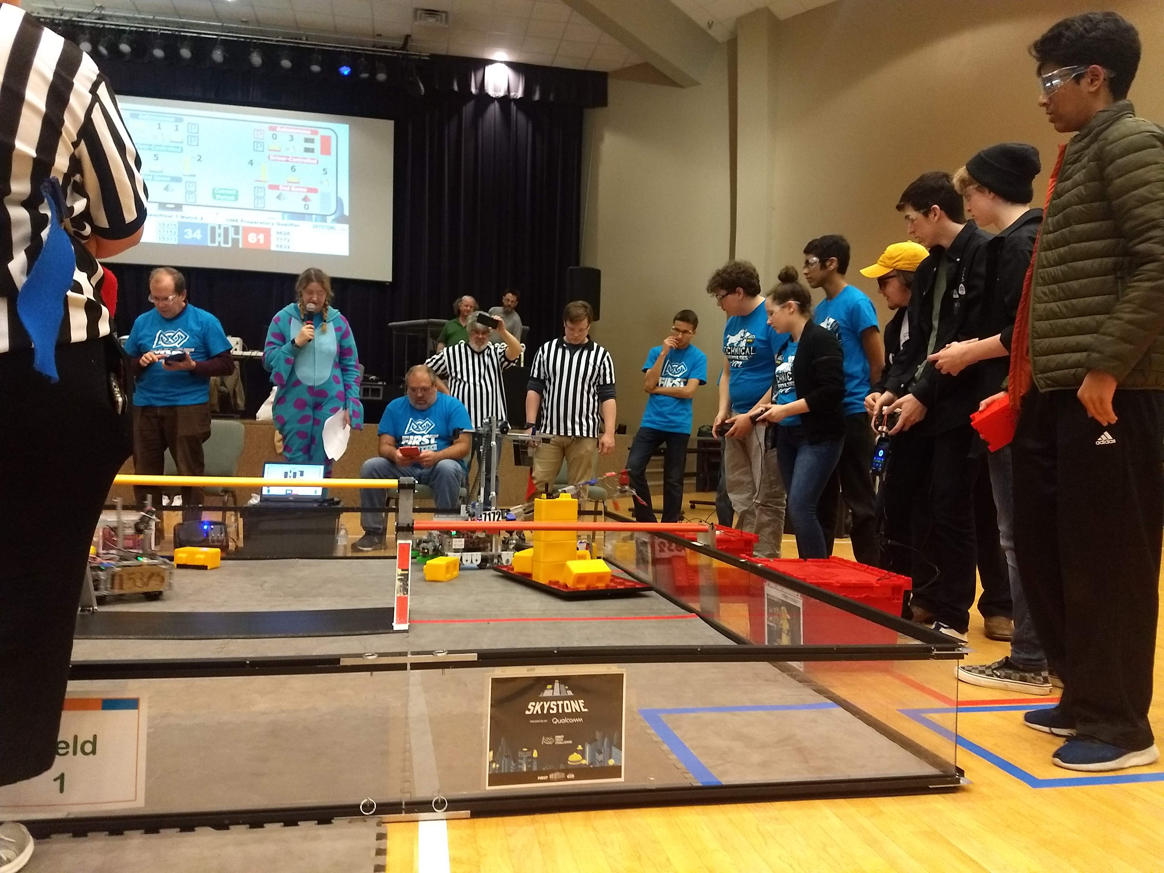
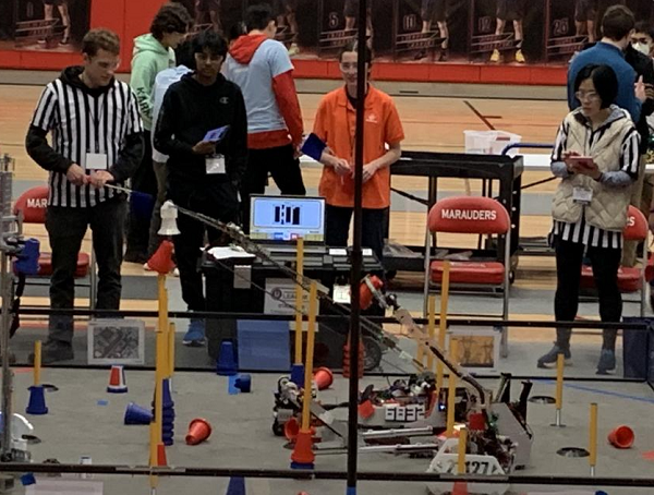
As for gameplay at both events, it did not go as smoothly as we would have liked. We did face some trouble during sizing but managed to get the robot to fit. Here is a game-by-game account of each of our matches. Overall we went 1-11 and managed to transfer and score 3 times in total across both days. Some key notes to mention were that we did not have a working autonomous at all and thus did not run one in any of our matches.
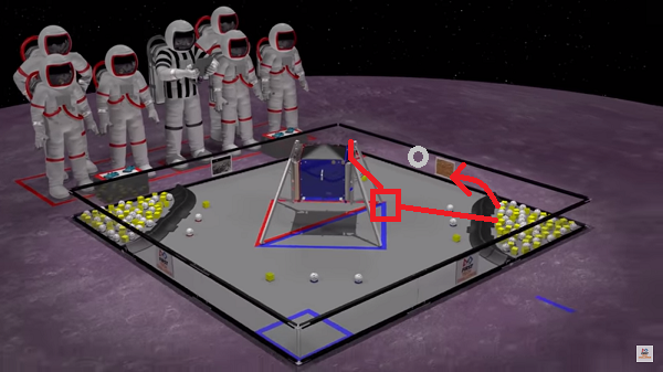
Texas UIL
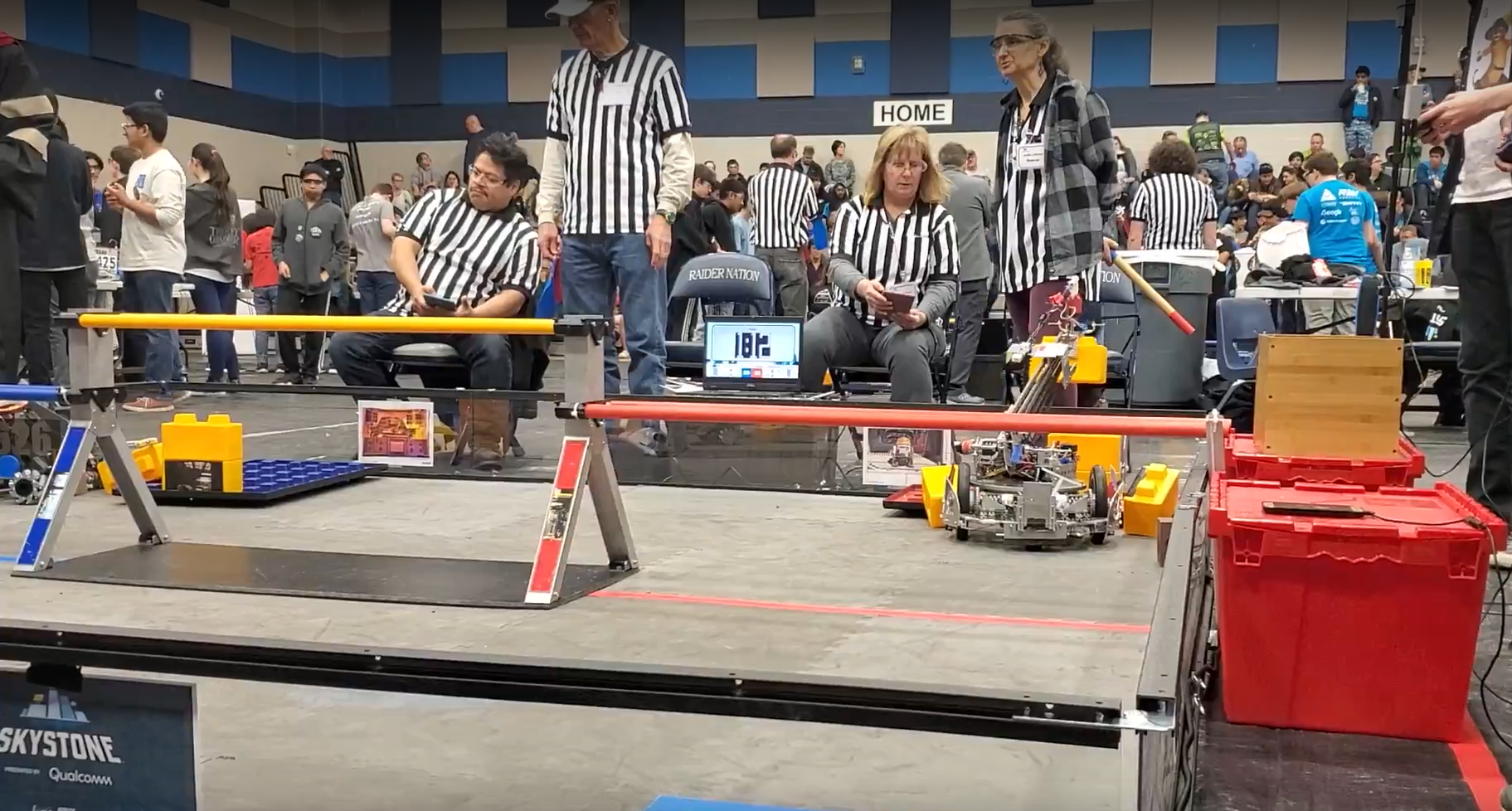
Match 4: 60 - 47 Loss
In the autonomous period, our robot did not move at all. During the teleop period, our robot hit one cone out of the substation, scored one cone, knocked another cone down, and grabbed the cone in intake, but the transfer didn’t work, and during the endgame, we were not able to score our beacon.
Match 7: 181 - 73 Loss
During the autonomous period, our robot did not move at all. In the teleop period, we had issues controlling UnderArm and determined that our driver synchronization needed to be worked on. In addition, our Crane was acting glitchy, and our flipper gripper wasn’t working. In the endgame, our robot was completely stationary the whole time.
Match 16: 251 - 75 Loss
During the autonomous period, our robot did not move at all. In the teleop period, we picked up a cone, put it back down, picked up a cone, and dropped it. During the endgame, the transfer worked, and we scored a cone. Some additional notes we took include that while transfer worked, it was inconsistent and slow (15-20 seconds for transfer, not including scoring).
Match 25: 144 - 20 Loss
During the autonomous period, our robot did not move at all. During teleop, our Crane was glitching again, and our UnderArm picked up a cone, but the Crane dropped it while trying to deposit it. Our Crane kept glitching in the endgame, but UnderArm worked to some degree.
Match 29: 171 - 83 Loss
During the autonomous period, our robot did not move at all. During teleop, our UnderArm struggled to pick up cones more than usual, and the transfer messed up. During the endgame, the robot demonstrated the same behavior as in teleop.
Match 34: 107 - 55 Loss
During the autonomous period, our robot did not move at all. During teleop, something went wrong in the shoulder of the UnderArm, and the robot stopped operating. During the endgame, the robot was stuck and couldn’t move due to the prior issue.
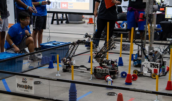
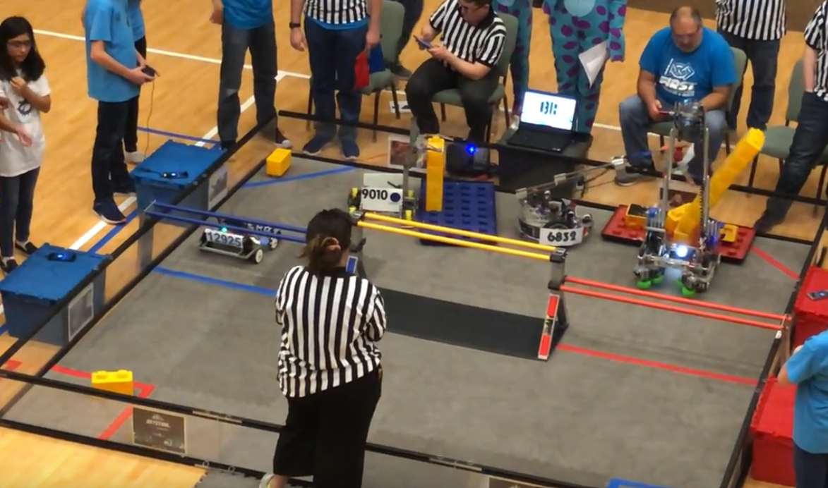
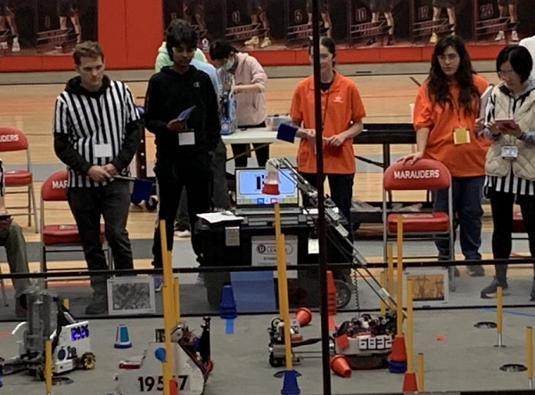
FTC State Championship
Match 9: 226 - 97 Loss
During the autonomous period, our robot did not move at all. During the teleop, we lost 20 points in penalties (our side). Our alliance partner wouldn’t let us go to the substation for cones, but we picked up a cone from the ground and scored. We picked a cone up from the substation, but the transfer didn’t work. During the endgame, we were not able to score our beacon..
Match 18: 280 - 29 Loss
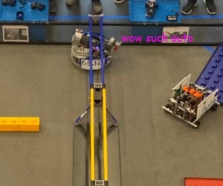
During the autonomous period, our robot did not move at all. During teleop, the robot took long to recalibrate and transfer and couldn’t fully grab a cone. During the endgame, the turret started rotating. One thing to note was that referees said our sizing wasn’t proper (even though it was). We had to turn our robot 45 degrees, which contributed to the late start of recalibrating, which we later challenged but did not amount to anything.
Match 26: 110 - 97 Loss
During the autonomous period, our robot did not move at all. During teleop, we picked up a cone, the transfer worked, and a cone was scored; a cone got stuck but was transferred after a cancellation, and we scored a cone. During the endgame, the Crane got stuck on a pole.
Match 32: 111 - 79 Loss
During the autonomous period, our robot did not move at all. During teleop, we picked up a cone, but the transfer didn’t work, and this happened multiple times. We pulled from the cone stack during the endgame, but it didn’t land on the pole when we deposited them.
Match 39: 242 - 165 Loss
During the autonomous period, our robot did not move at all. During teleop, the robot wasn’t moving; it was completely stuck. However, during the endgame, the robot was still stuck in position. Some things to note are that we queued late and didn’t have time to run the full calibrate sequence and ended up stopping to stop the robot from breaking itself. We also started without calibration because we were told we would incur penalties. This is definitely something we can improve on.
Match 48: 144 - 88 Win
During the autonomous period, our robot did not move at all. During teleop, the robot got into position, grabbed a cone, and hyperextended the wrist, so we switched to using the Crane as both intake and depositing. Unfortunately, during the endgame, we couldn’t get the beacon. One thing to note is that the wrist went limp and couldn’t be corrected through manual control.
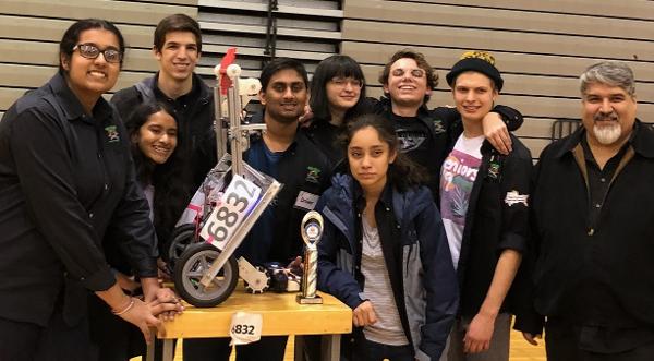
Even though TauBot was not up to par, we hope to spend the next 4 weeks fine-tuning it and truly turning it into a Worlds-level robot. More information on our takeaways and future plans will be discussed in our post-mortem, but we made it to Worlds at the end of the day.

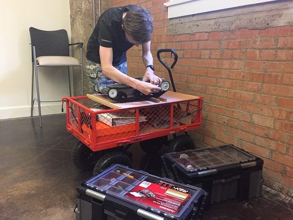
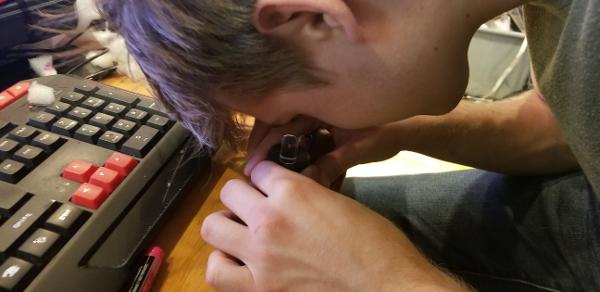
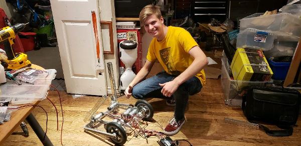
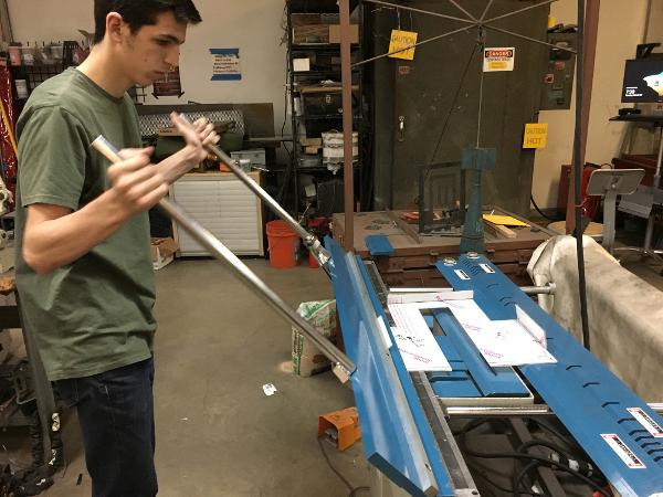
 Austin Lui of Technicbots gets their chassis ready for testing.
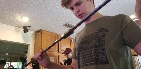
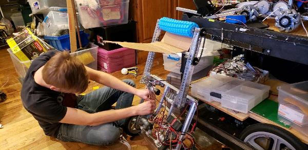
 Connor Mihelic of EFFoRT adds some finishing touches.


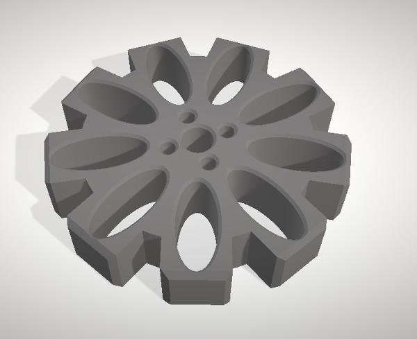
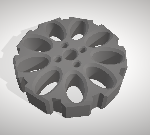
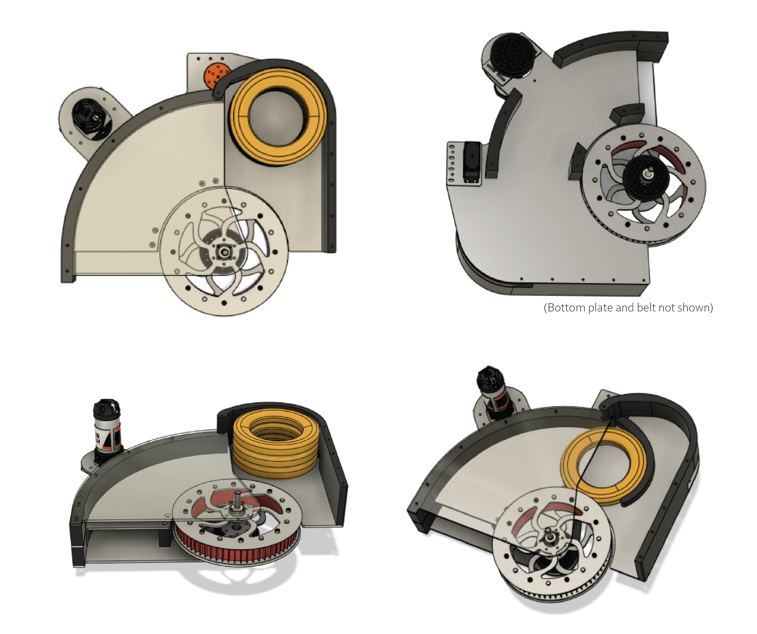
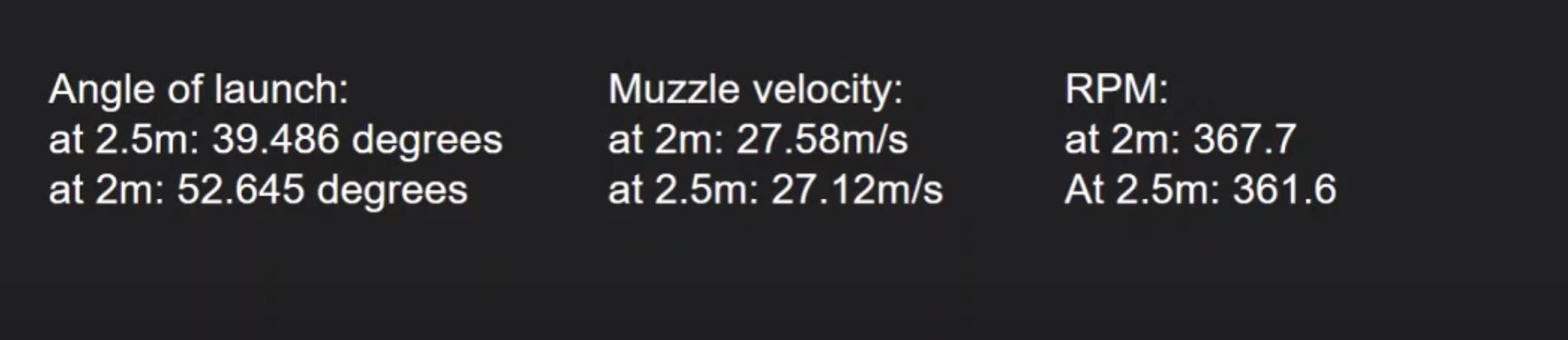
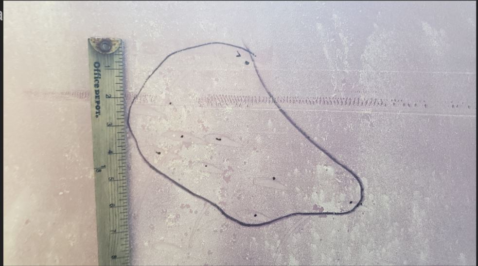
 This suggestion uses a plastic flap to "trap" game elements inside it, similar to the lid of a soda cup. You can put marbles through the straw-hole, but you can't easily get them back out.
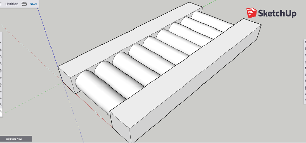
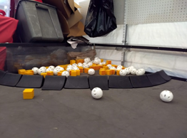
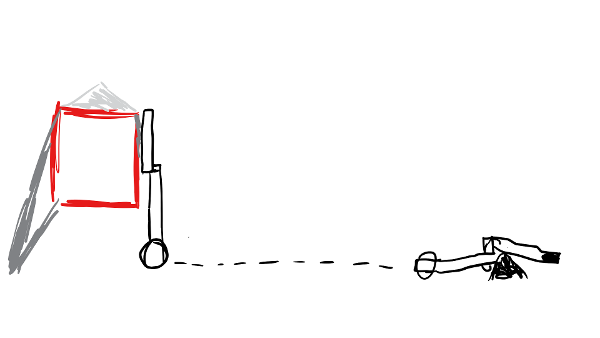
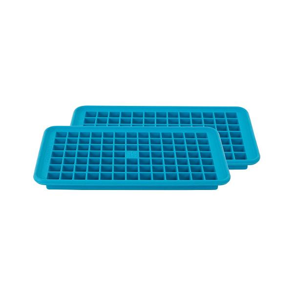
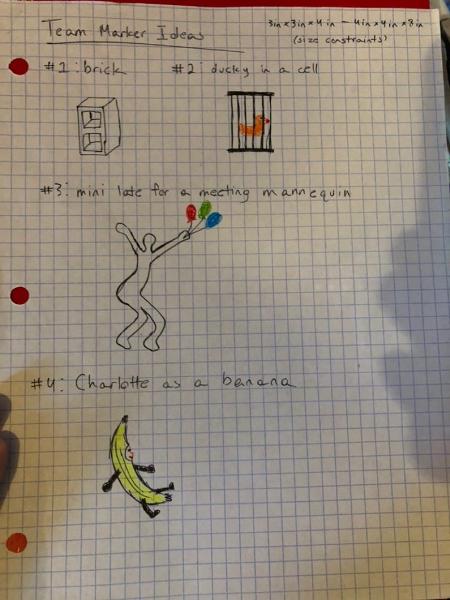
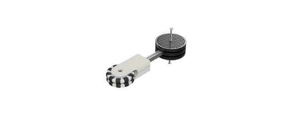
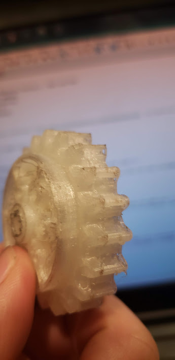
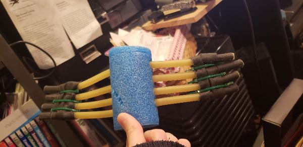
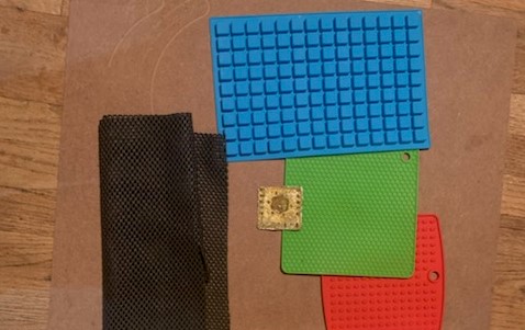
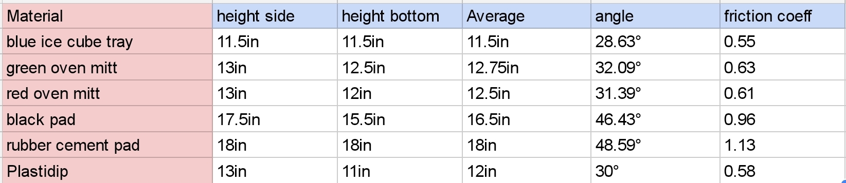
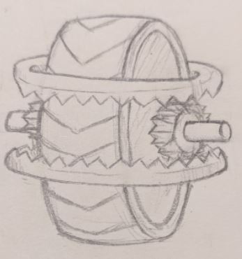
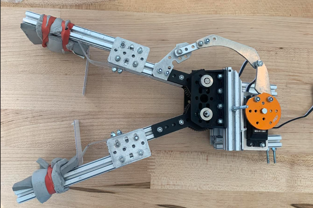
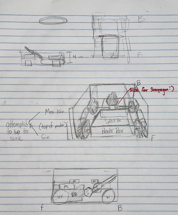
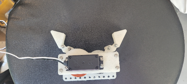
 This one is simple - a linear slide arm attached to a motor so that it can pick up game elements and rotate. We fear, however, that many teams will adopt this strategy, so we probably won't do it. One unique part of our design would be the silicone grips, so that the "claws" can firmly grasp the silver and gold.
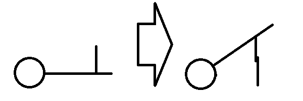
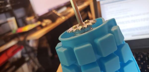
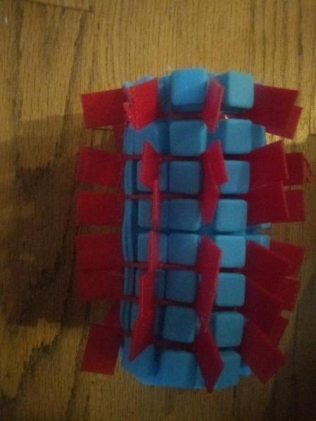
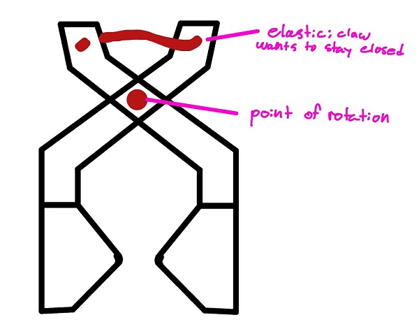
 When we did Res-Q, we dropped our robot more times than we'd like to admit. To prevent that, we're designing an interlocking mechanism that the robot can use to hang. It'll have an indent and a corresponding recess that resists lateral force by nature of the indent, but can be opened easily.

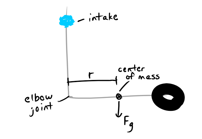
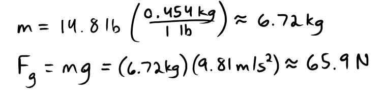
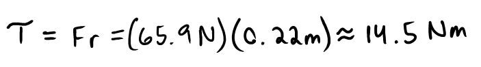
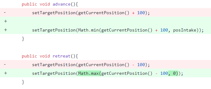
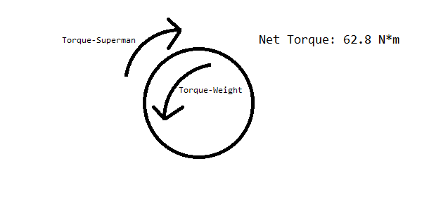
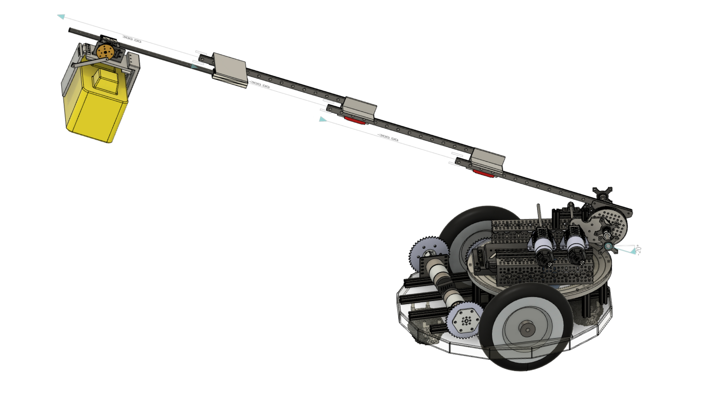
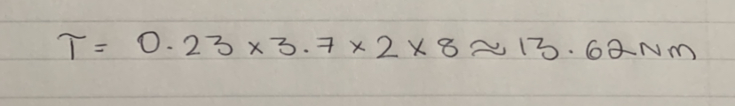
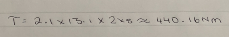
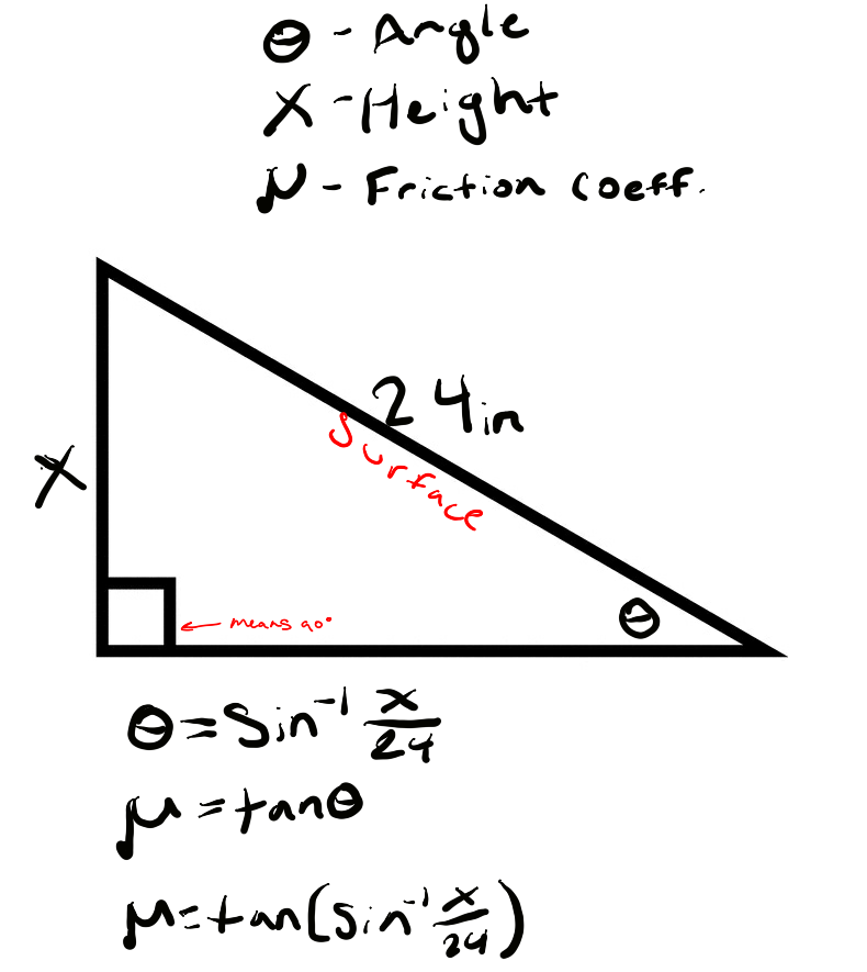
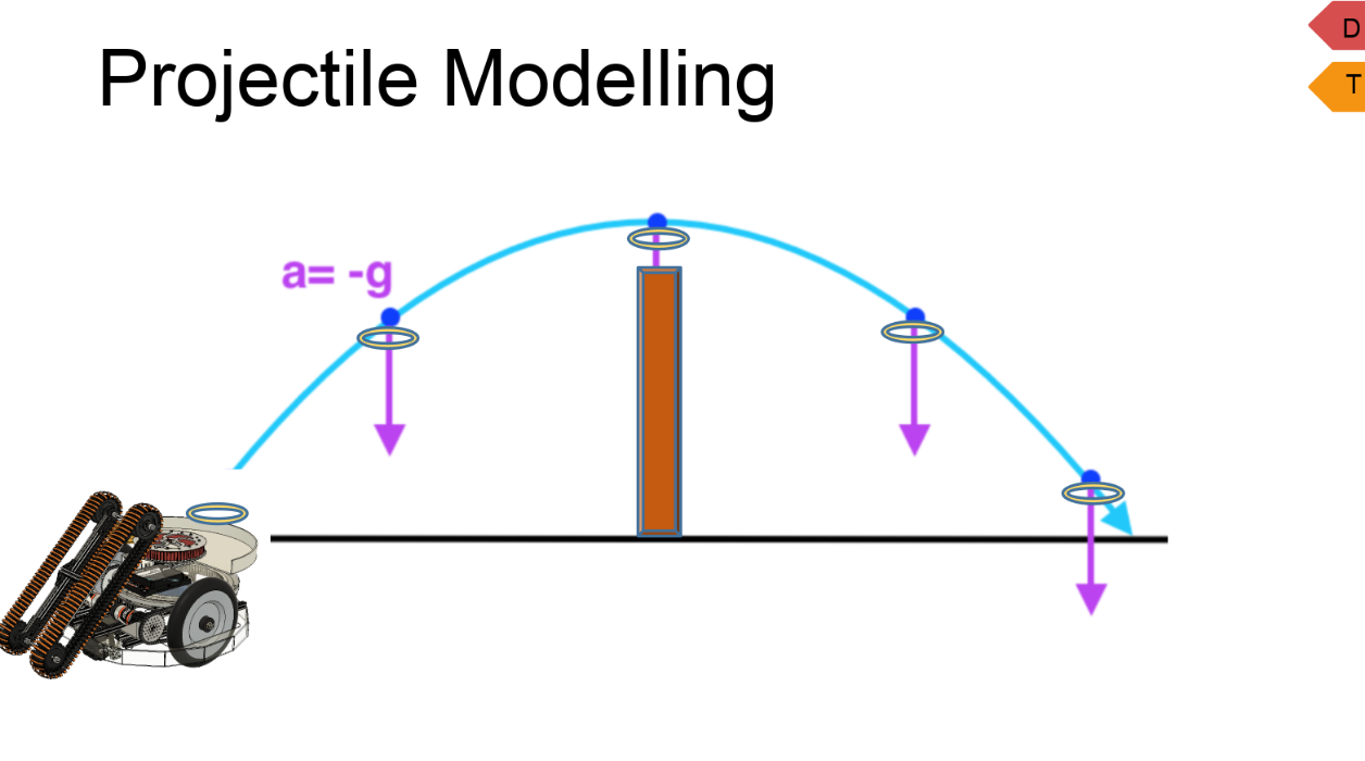
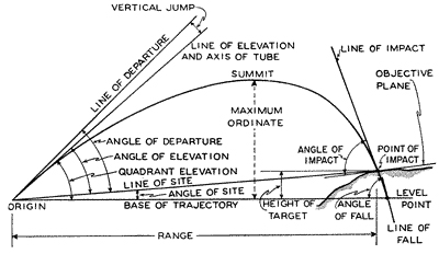
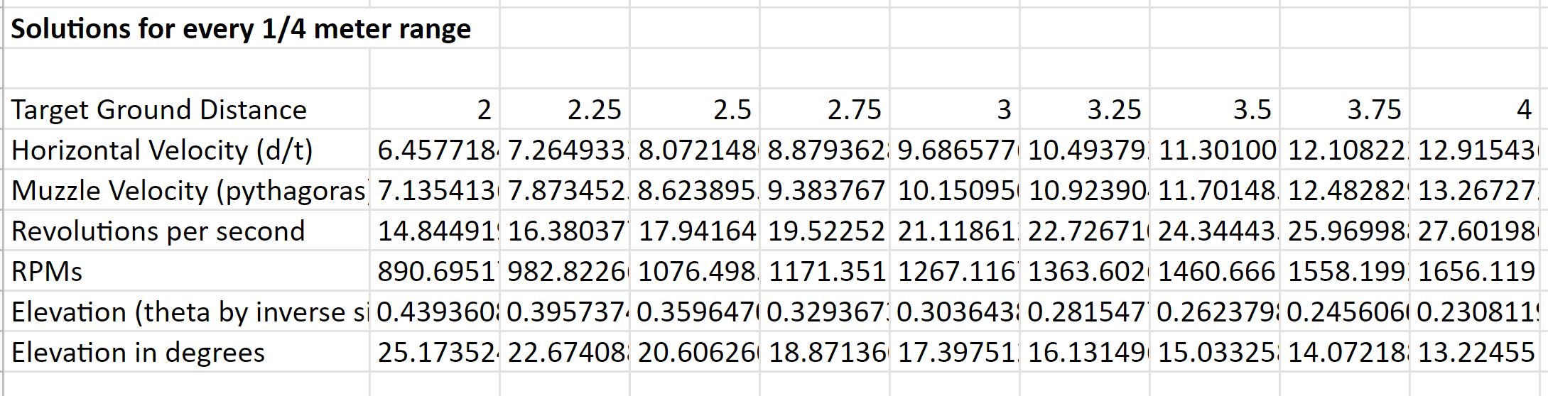
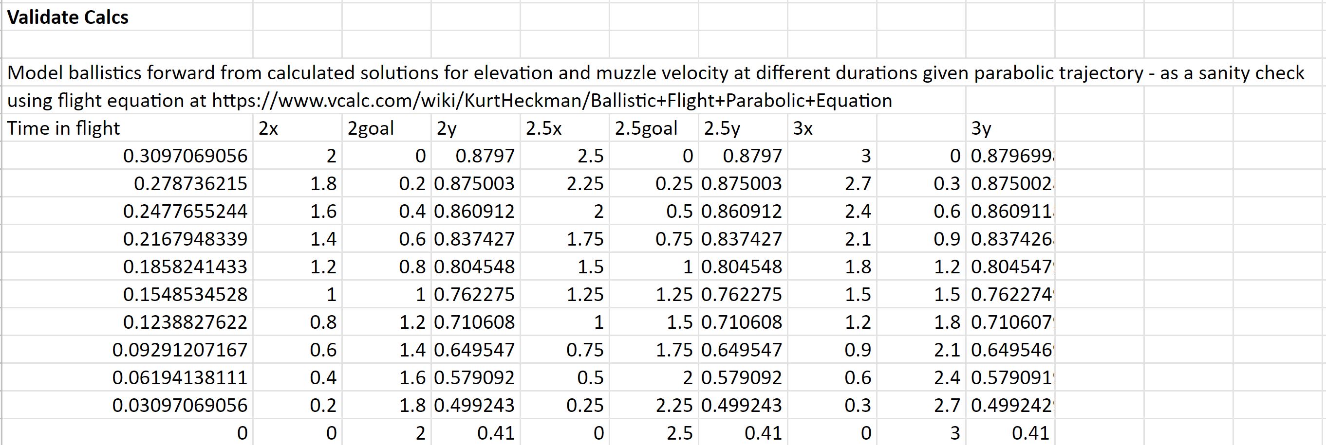
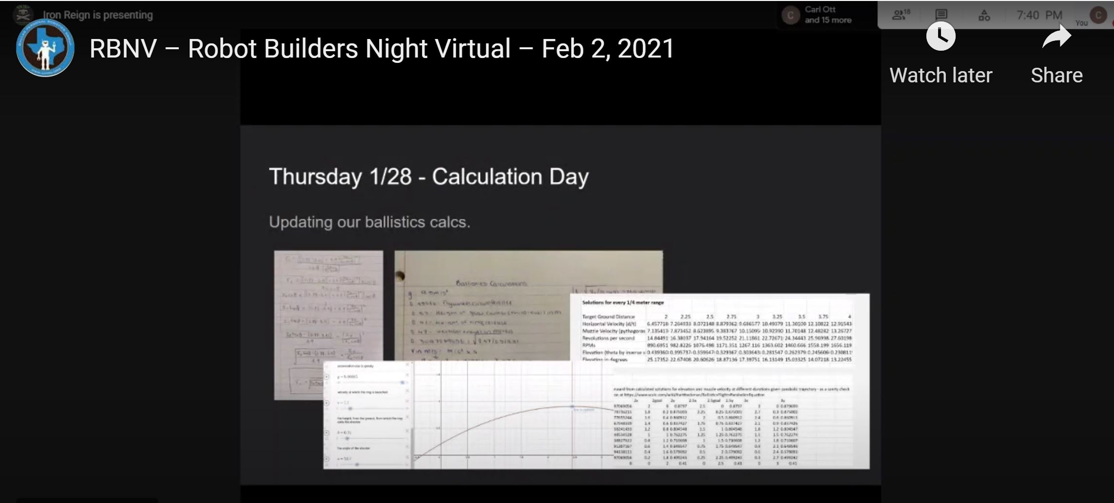
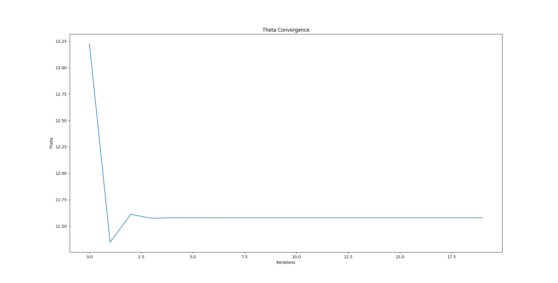
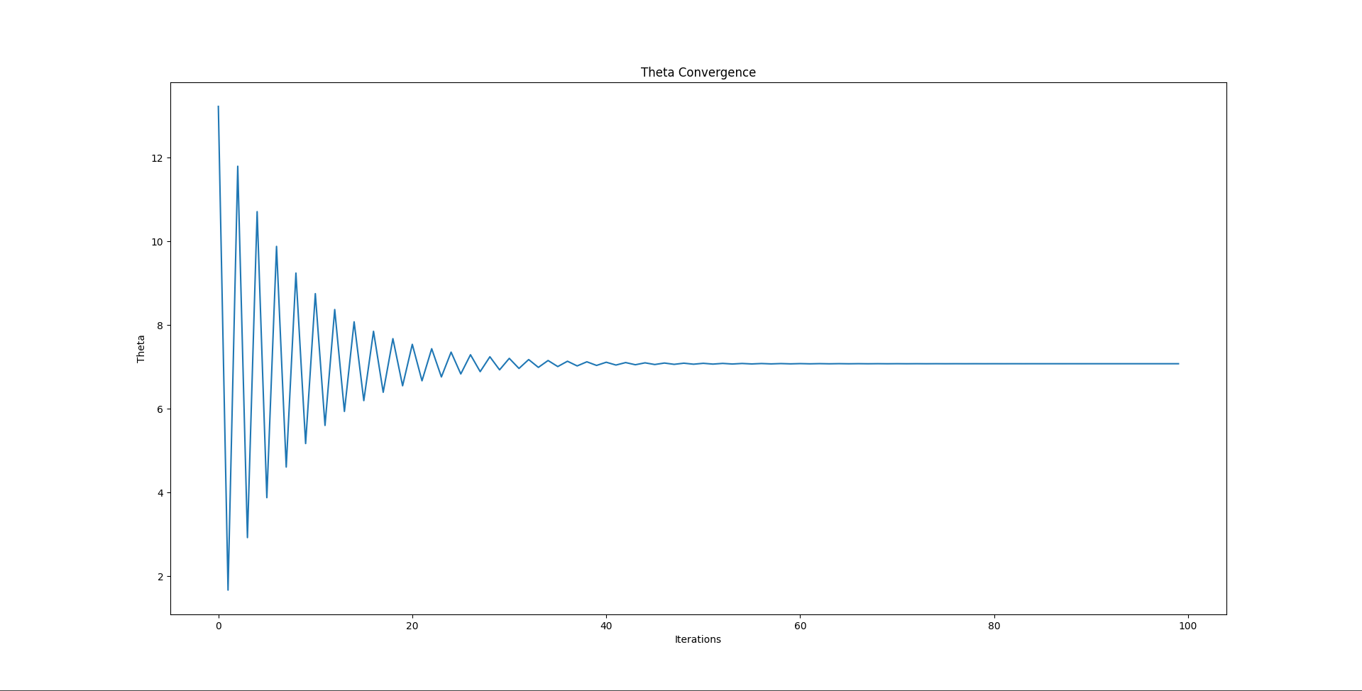
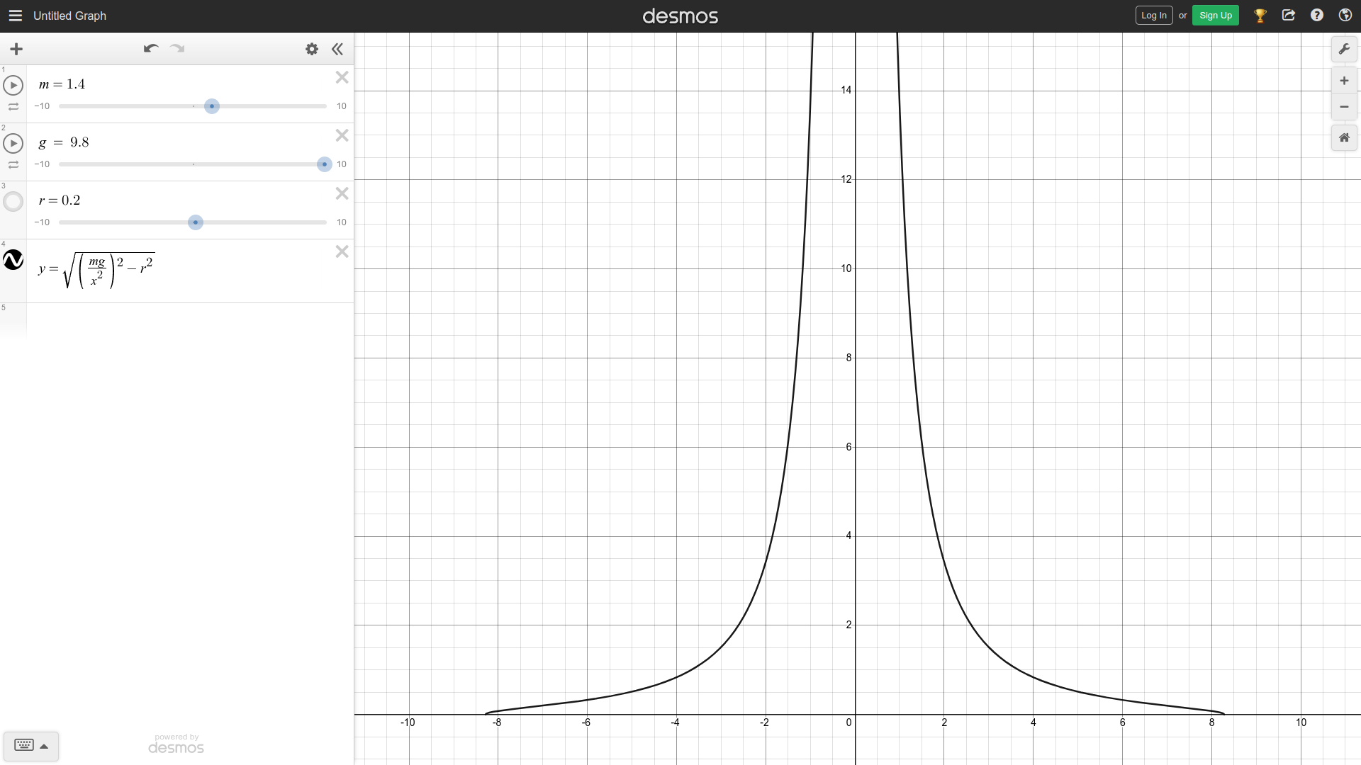
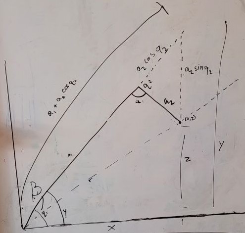
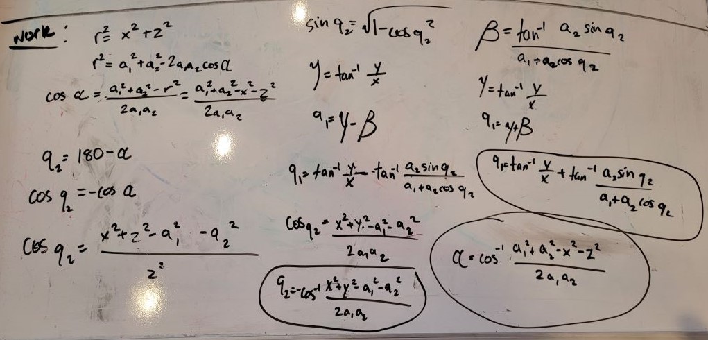
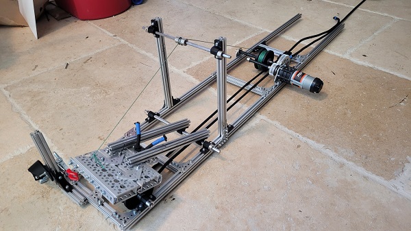
 Then we realized a more pressing issue. Since torque is equal to force * arm length (T=FR), and the force on our robot is only the force due to gravity (F=mg), we had a torque on the lift equal to T=mgR. Then, as the lift was mounted at the very end, the torque on the arm was at its absolute maximum. And, while we're confident in our building ability, we're not that confident. So, we realized that we'd have to move the lift closer to the middle to minimize torque.


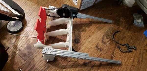

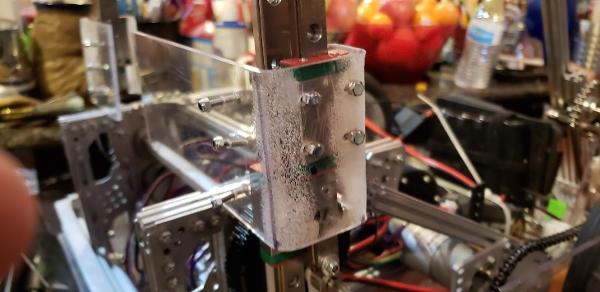
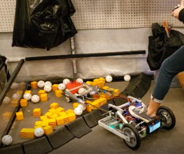
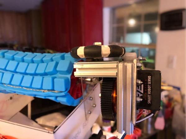
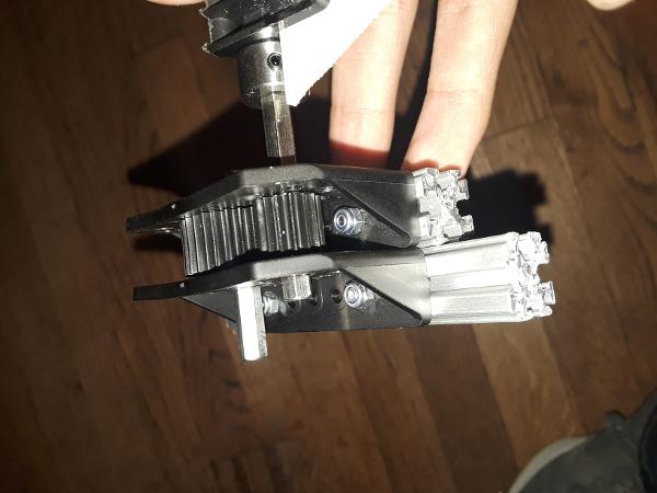


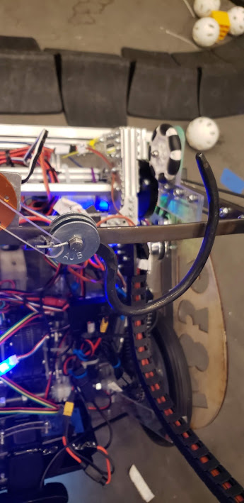
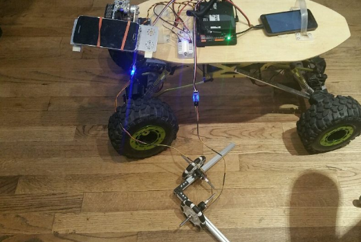
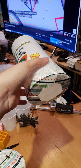
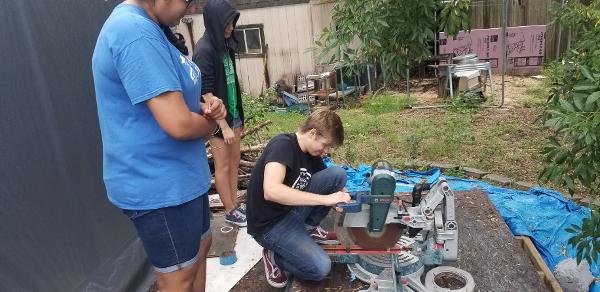
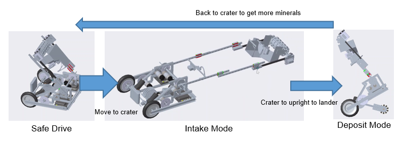
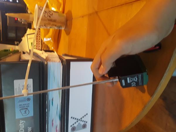
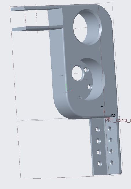
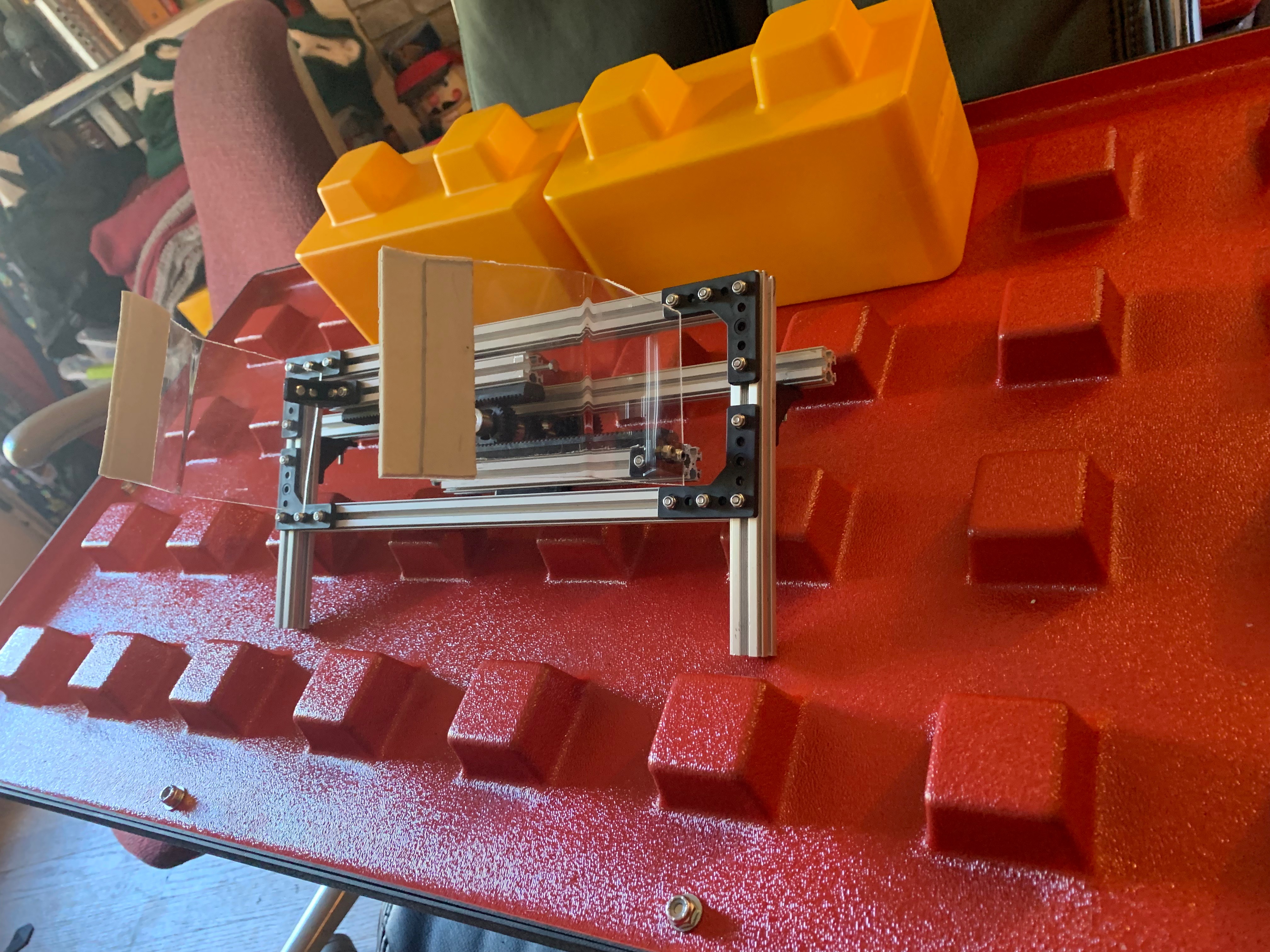
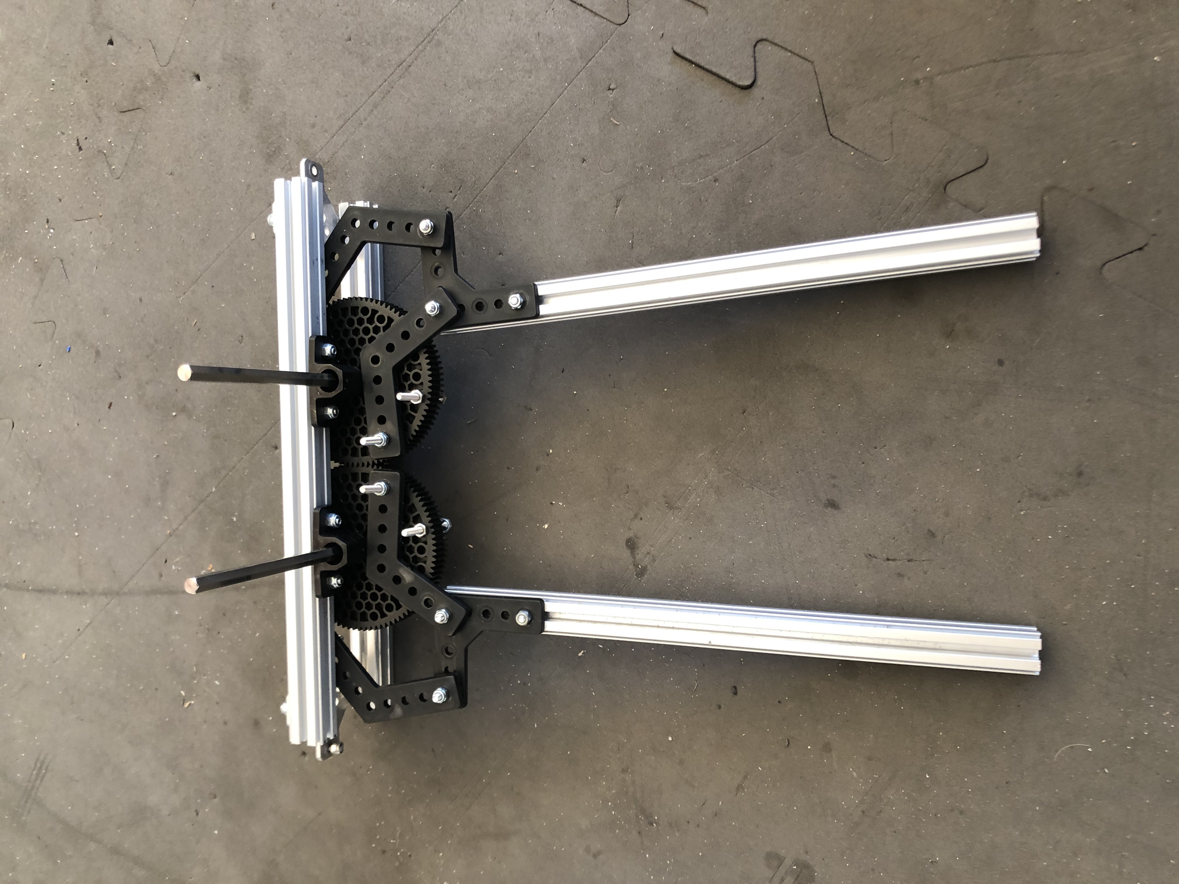
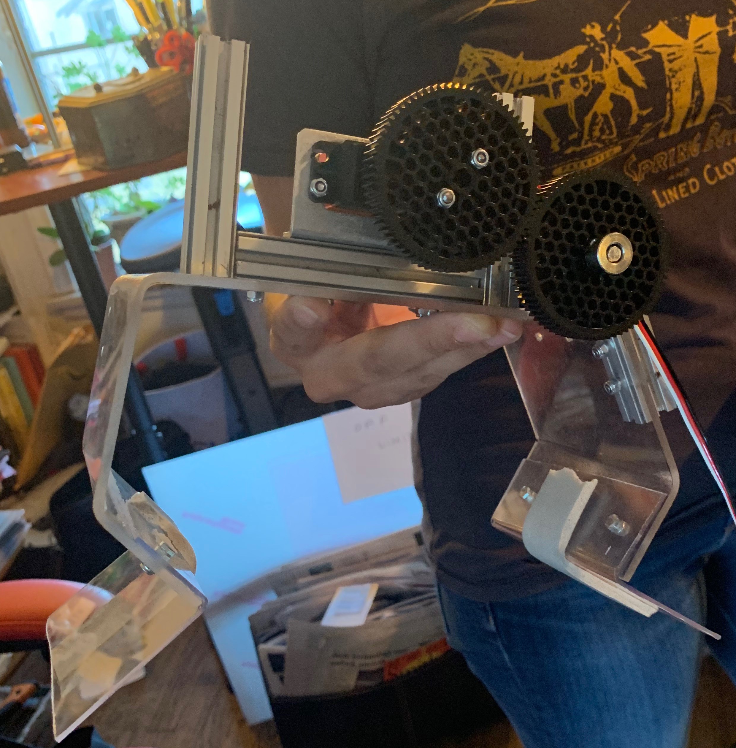
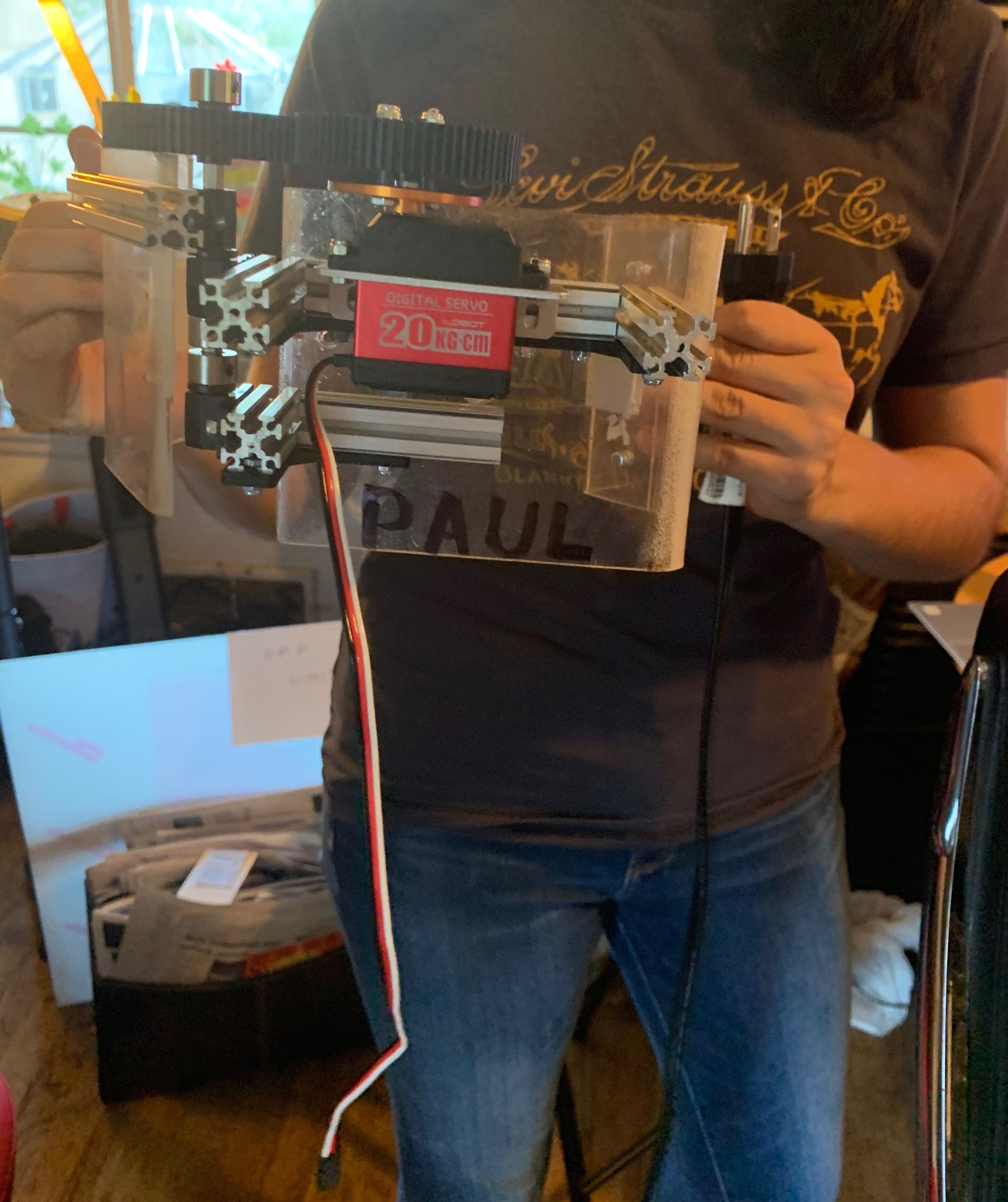
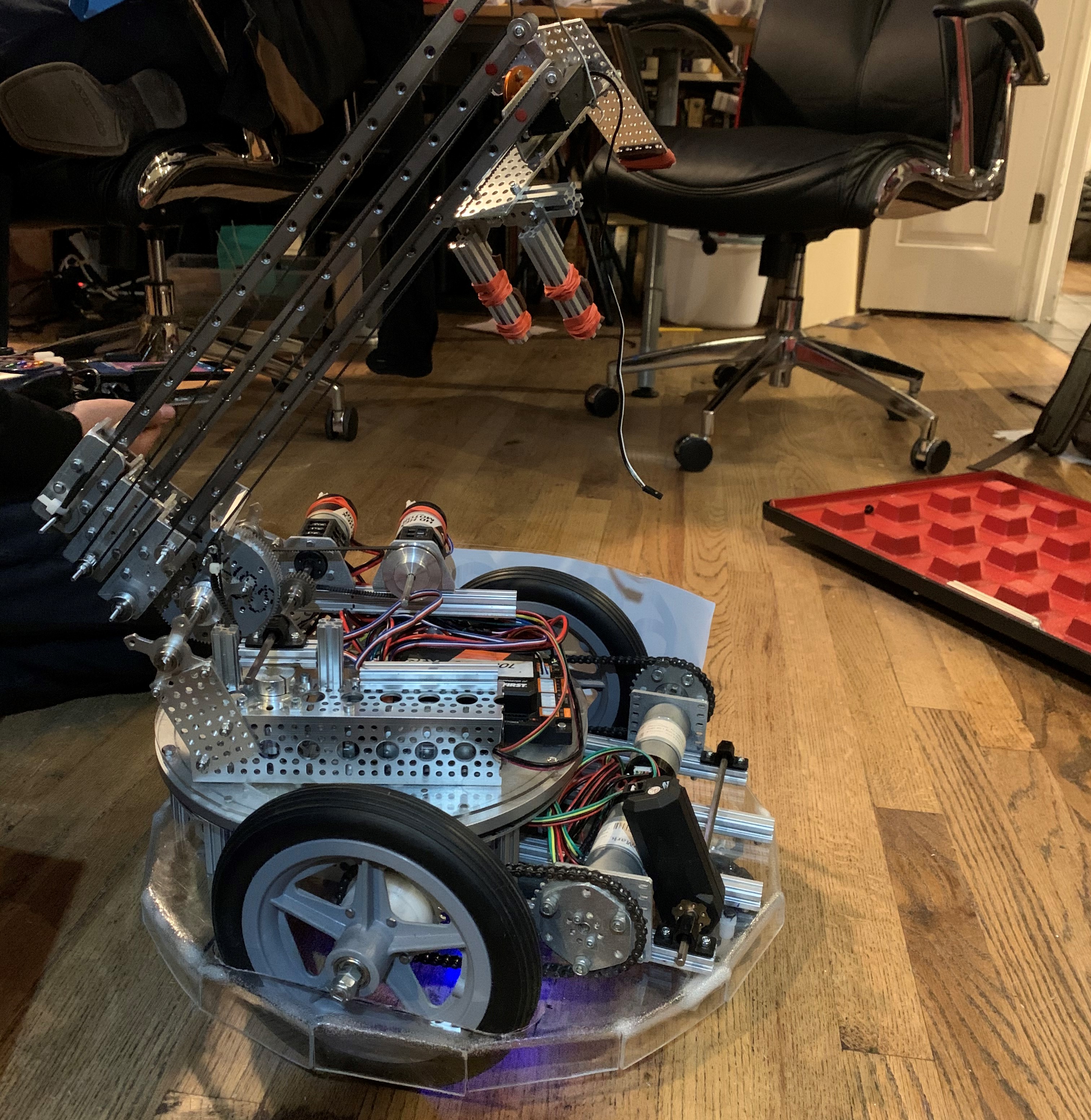
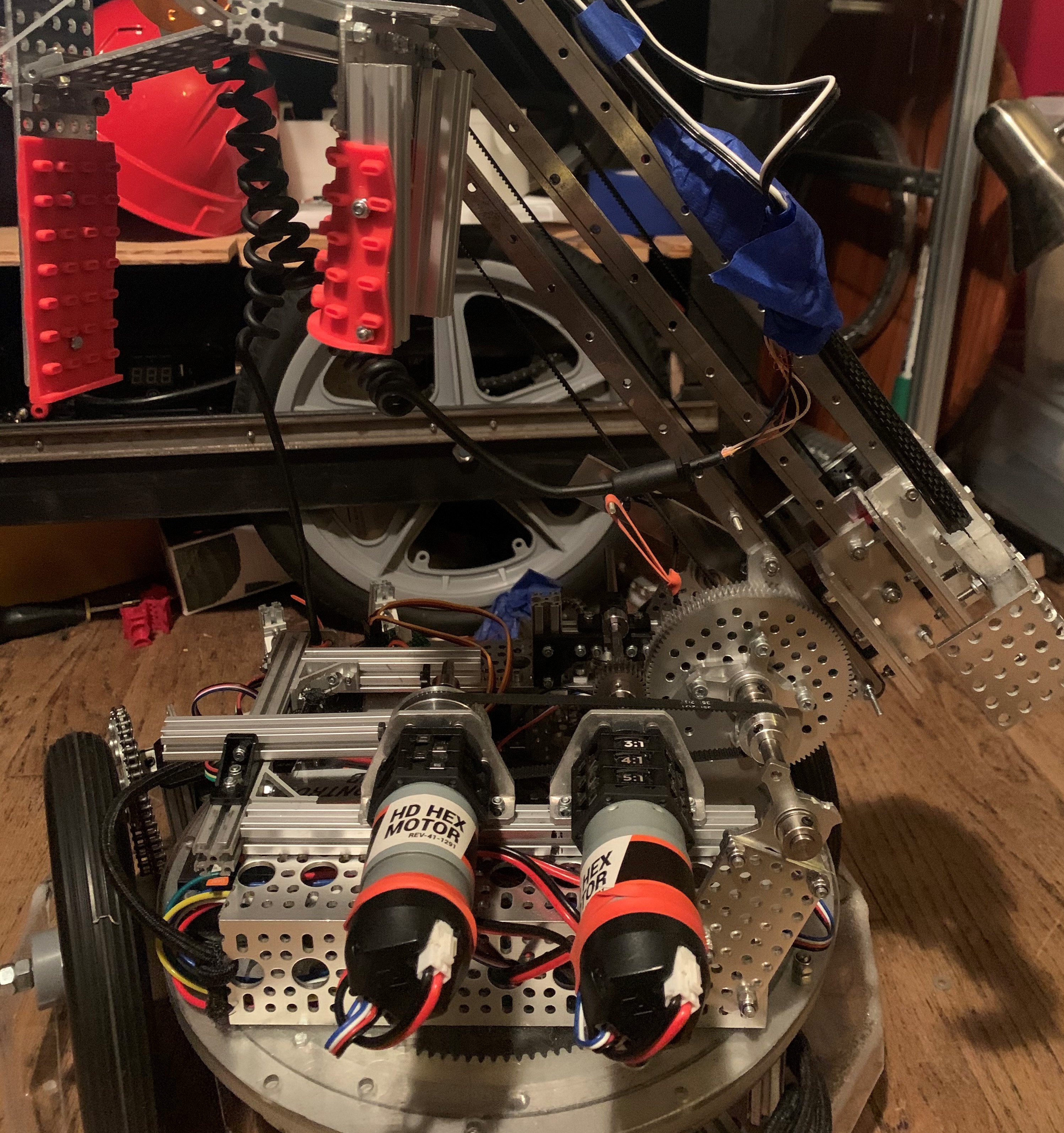
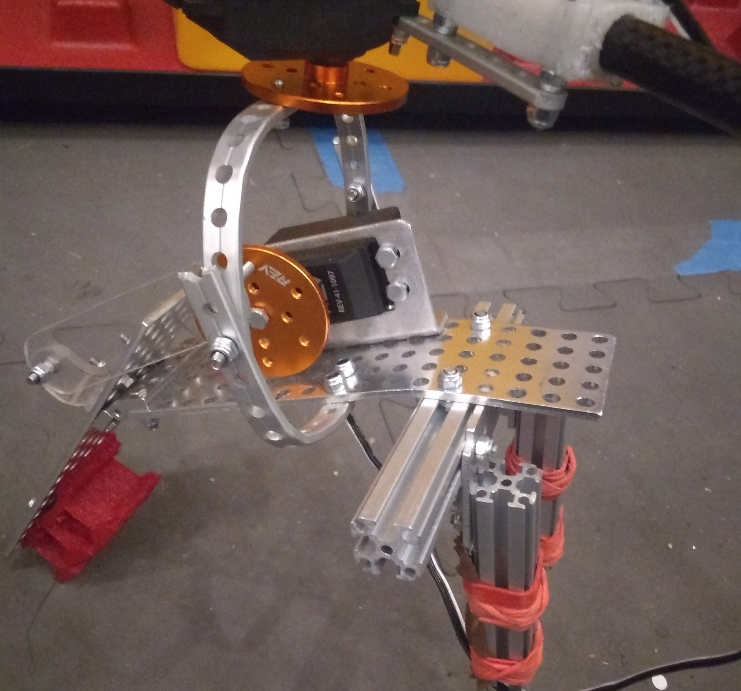
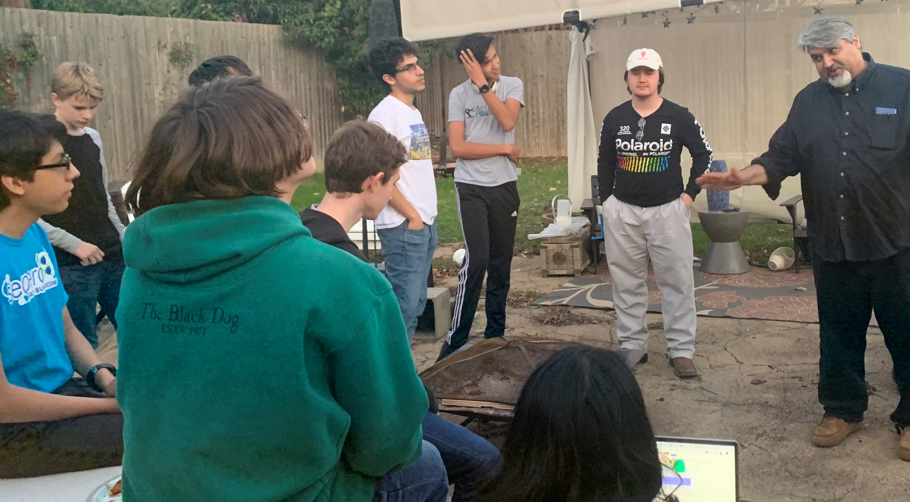
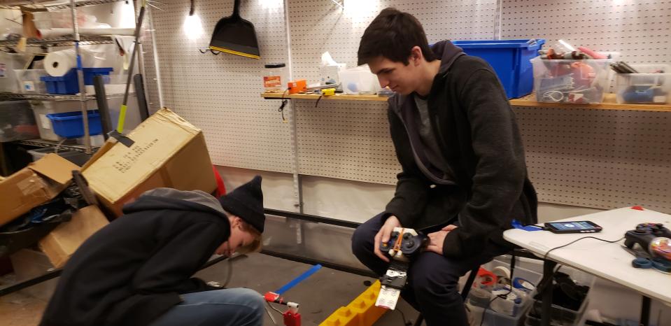
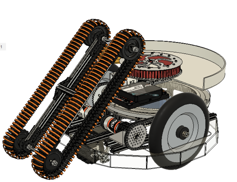
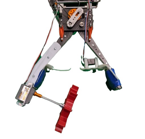
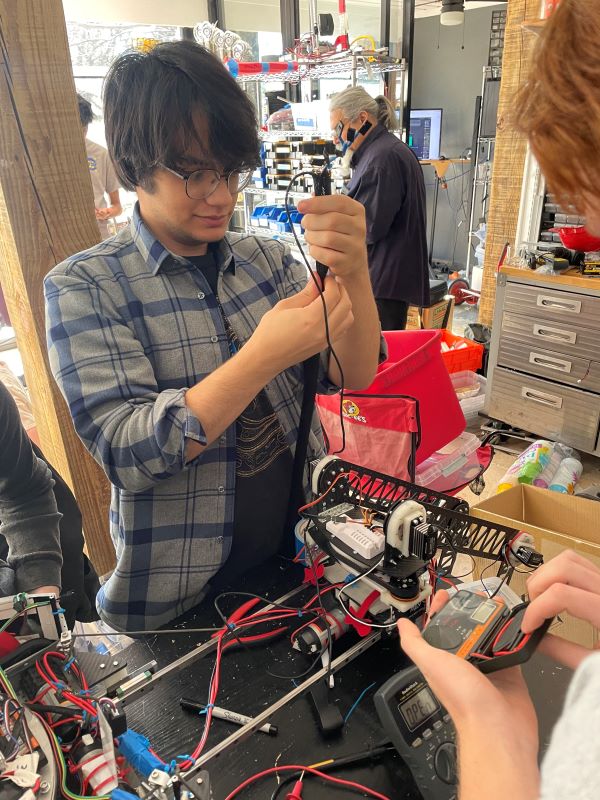
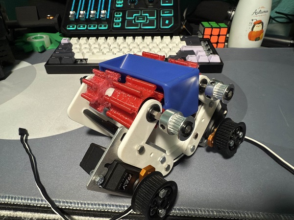
 Karina, Justin, and Jose practiced driving the robot. We discovered that the robot latches extremely well with the new hook and that the autonomous delatch works. We also tested the articulation, or poses, of our robot. The only issue that popped up was when the robot moves into deposit mode, it tips toward the side with linear slides, but Karina discovered that if she drives the robot forward at the same time, she can ram the robot into the correct position. Karina got to 4-5 cycles per match with the new updates. This practice was a way to test the strength of our robt - we've had our robot break under stressful situations previously - and this time nothing broke. The biggest issue was that a servo wire on our intake came unplugged, but even with that, our robot still worked.
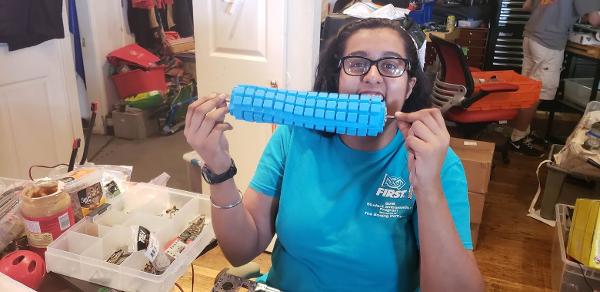
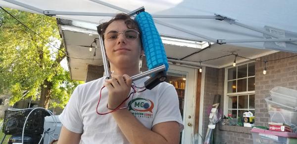
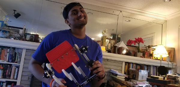
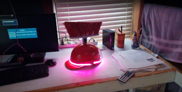 We finished the light-up LED hat.
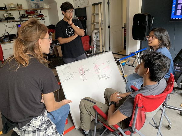
 Arjun continued writing the Control Award submission, adding in the new articulations and poses of the driver enhancements. Janavi created state diagrams for the code to add to the submission.


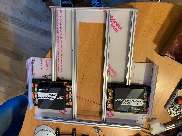
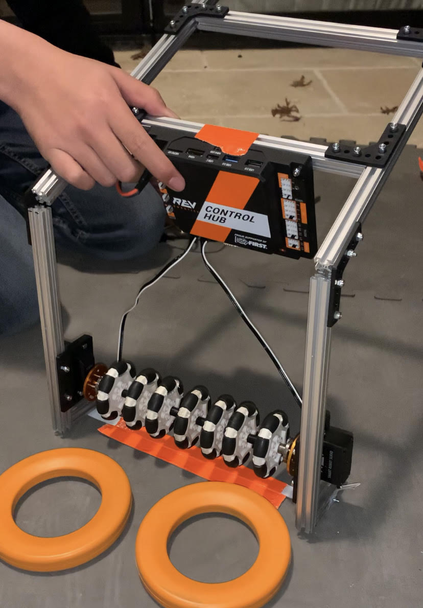
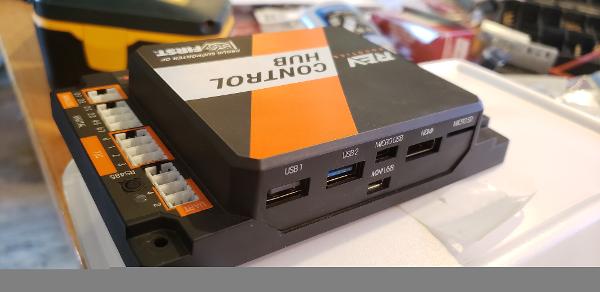 Iron Reign was recently selected to attend a REV Control Hub trial along with select other teams in the region. We wanted to do this so that we could get a good look at the control system that FTC would likely be switching to in the near future, as well as get another chance to test our robot in tournament conditions before Worlds.
 While testing it, we didn't have time to copy over our entire codebase, so we made a quick OpMode that moved one wheel of one of our old robots. Because the provided SDK is almost identical to ftc_app, no changes were needed to the existing sample OpModes. We successfully tested our OpMode, proving that it works fine with the new system.

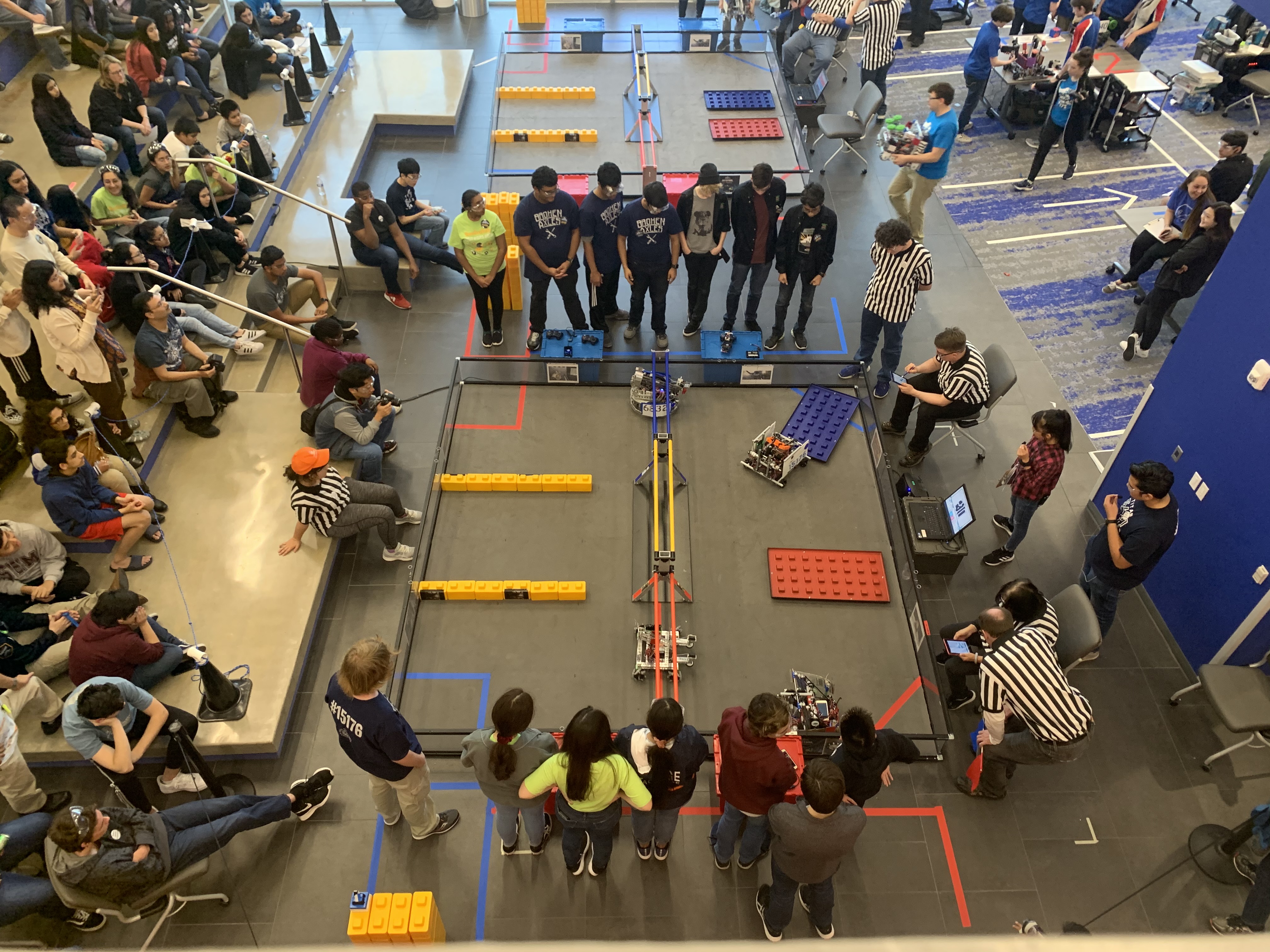
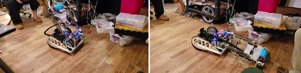
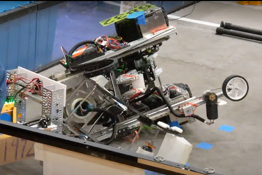
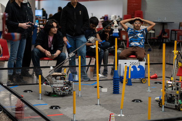
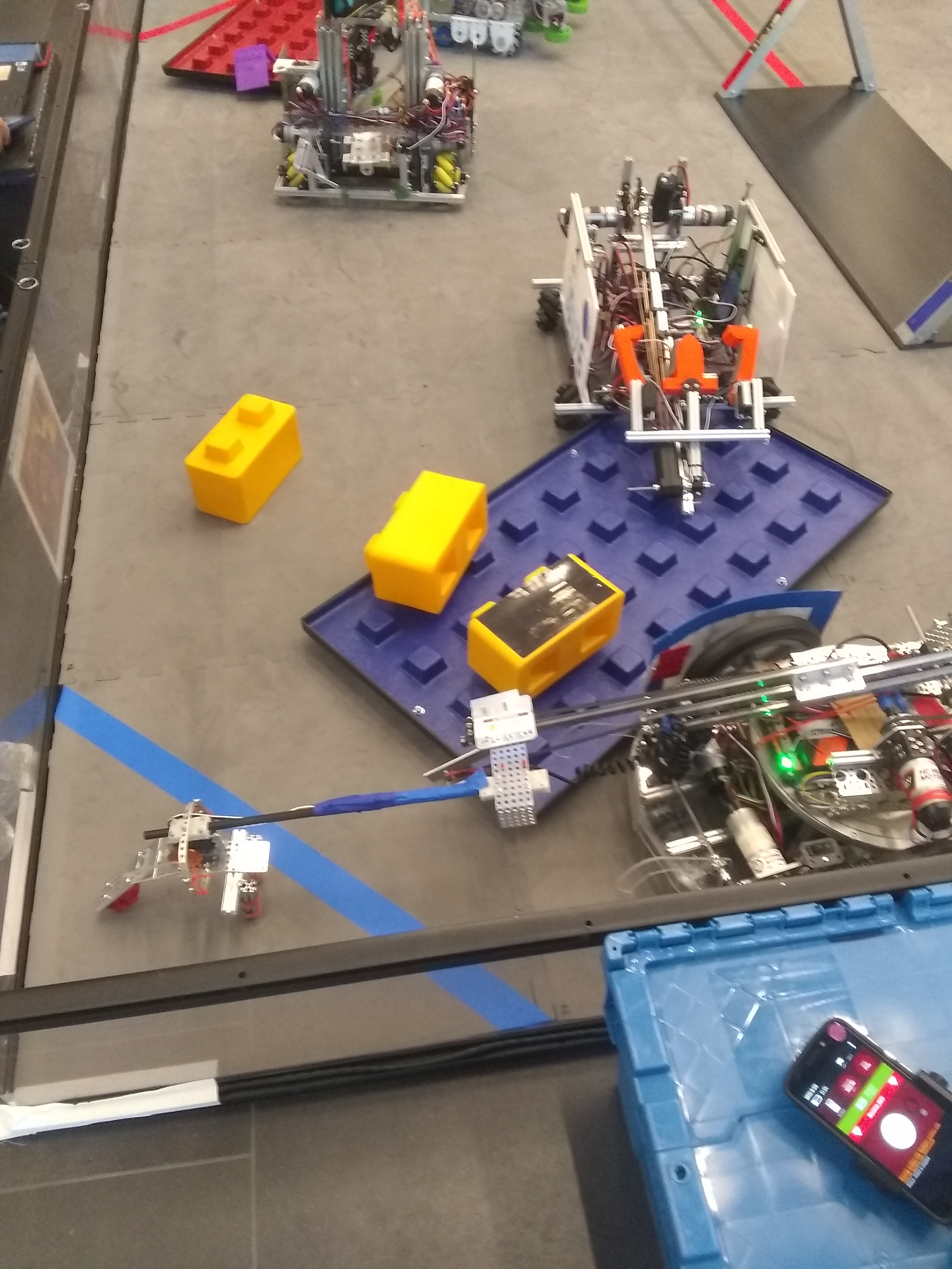 Finals 2
 Finals 2


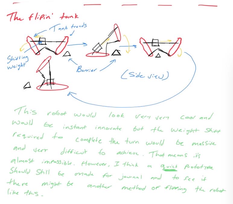
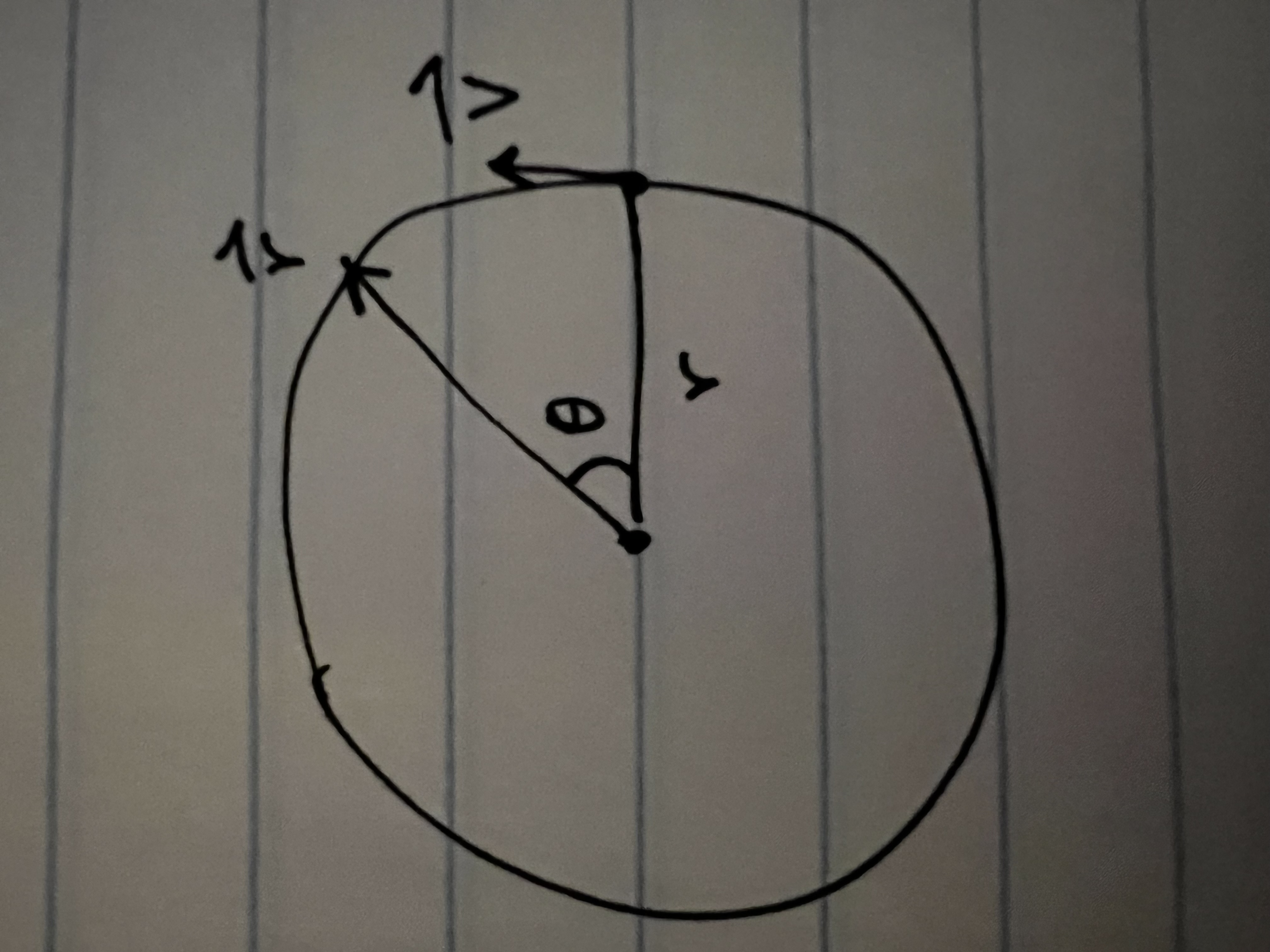
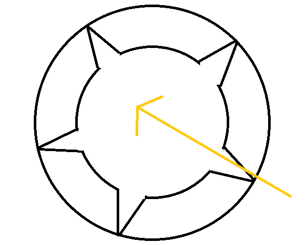
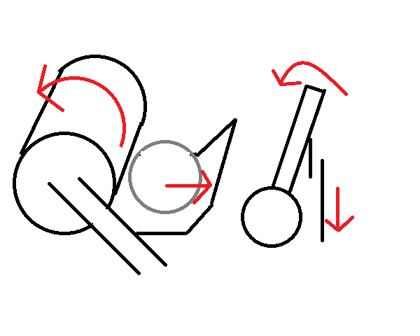
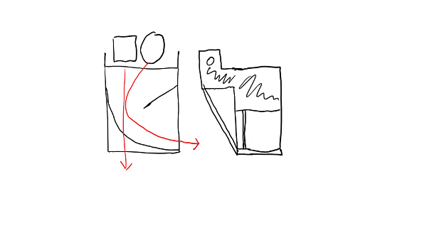
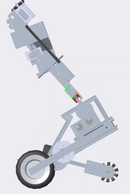
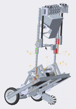
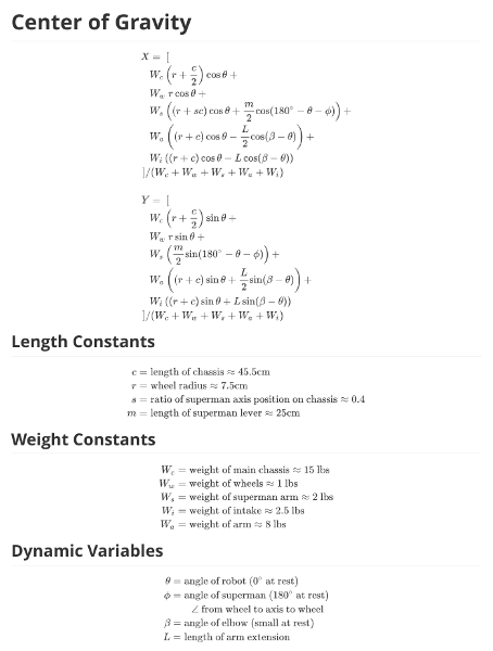
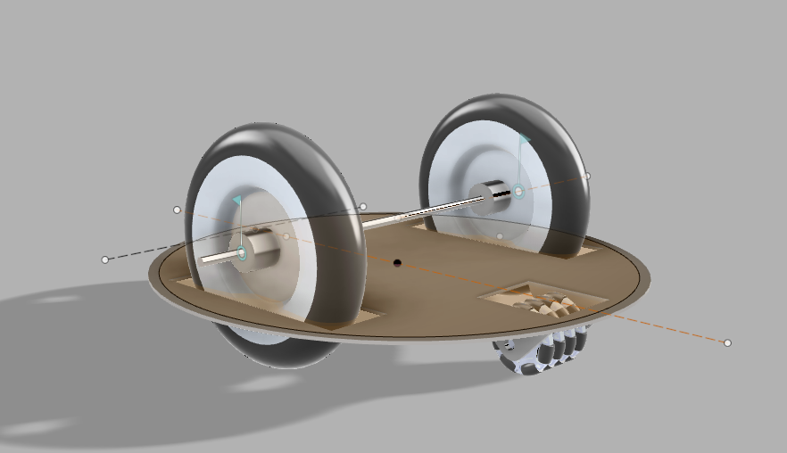
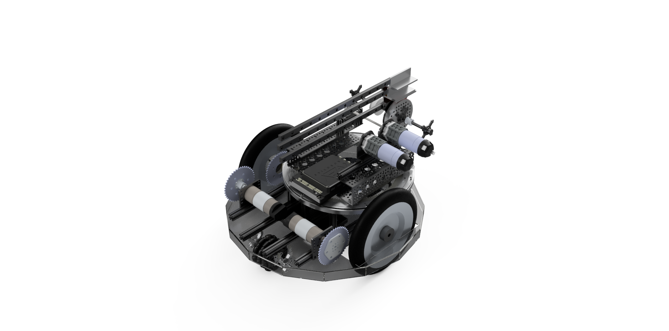
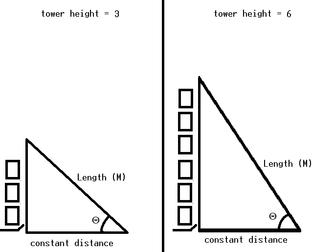
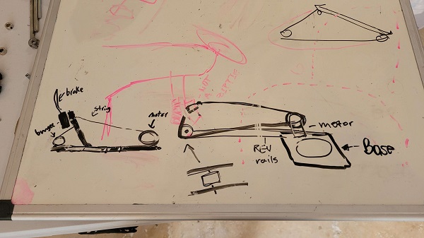
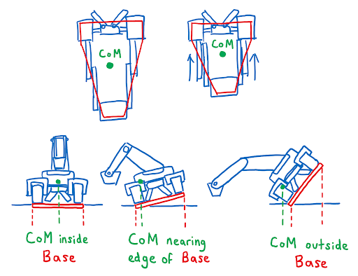 Looking at these diagrams of the robot and its center of mass, we can see how as the crane extends past the base of the robot, the center of mass moves towards the base. Eventually, the center of mass reaches a position outside of the base and the robot falls over. To solve this problem, we would have to either lower the center of mass or limit its fluctuation during movement.
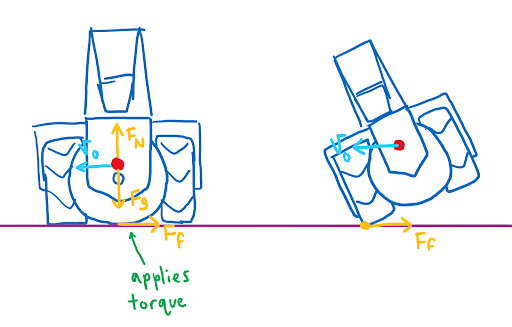
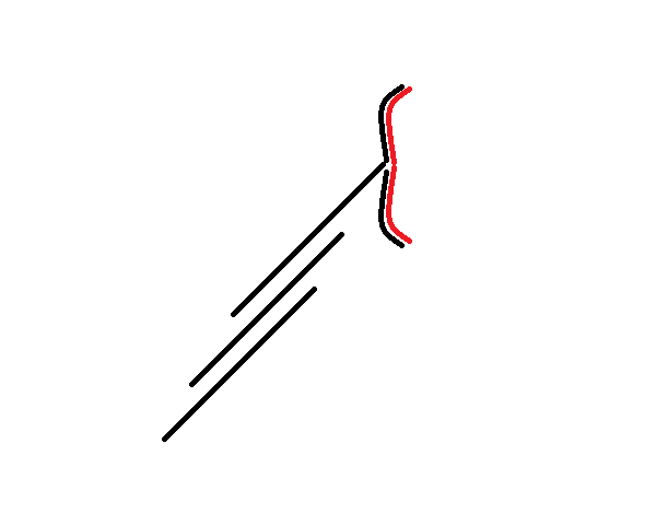
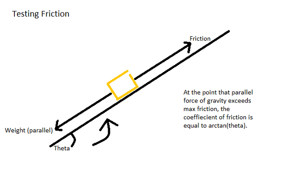
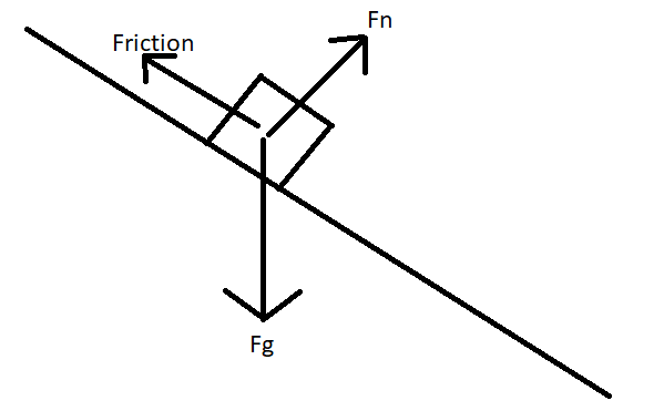
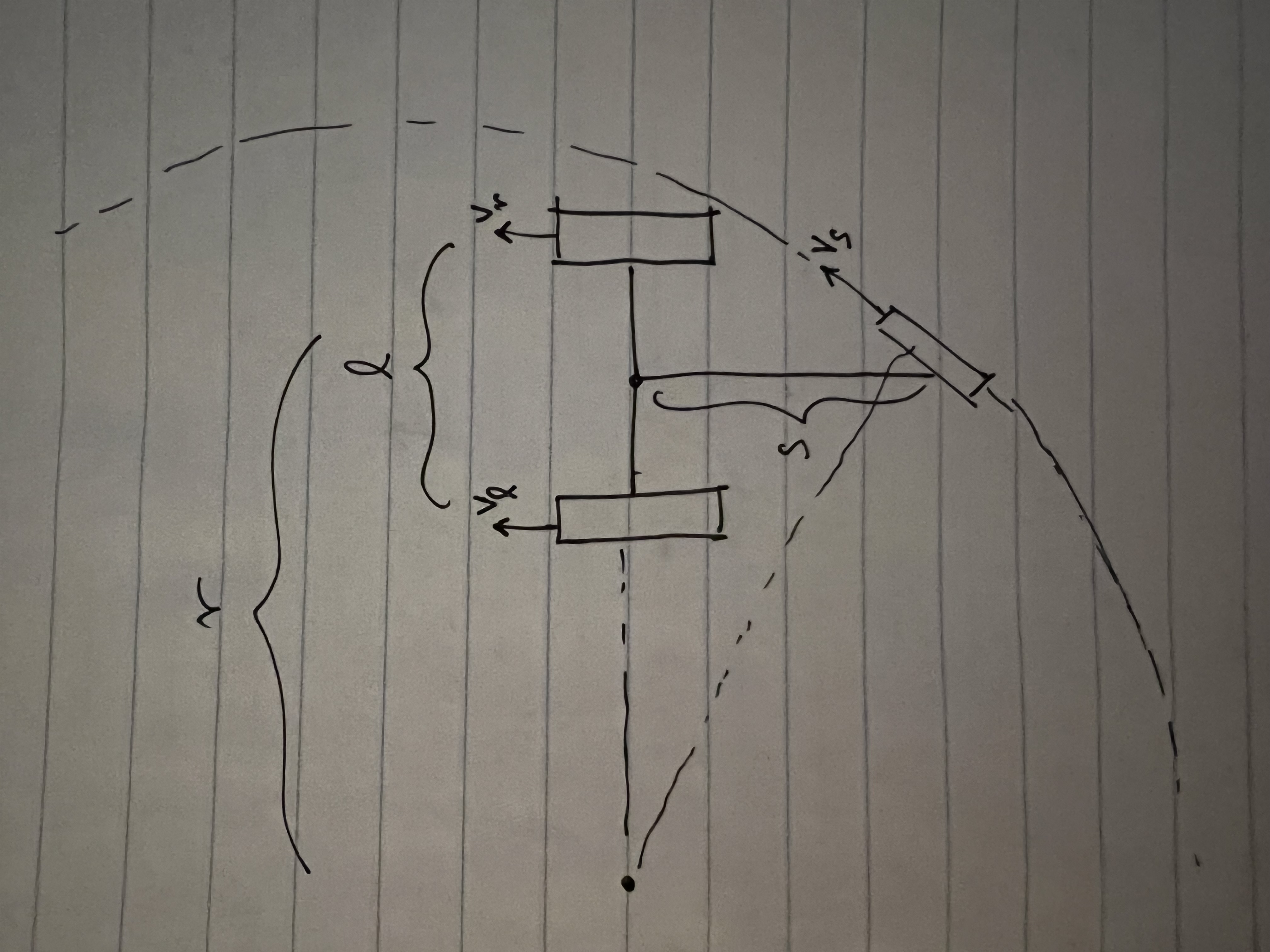
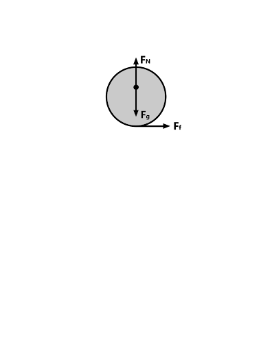 You can see from these free-body diagrams that as we lower the vertical component of the normal force, the overall rotational torque exerted by the swerve module is decreased, which inspired our decisions to lower the center of mass.
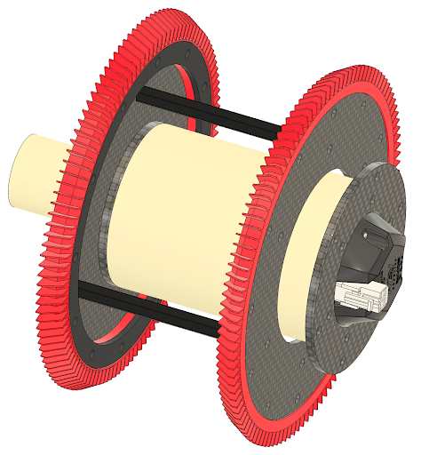
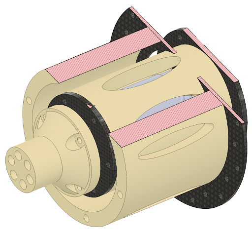
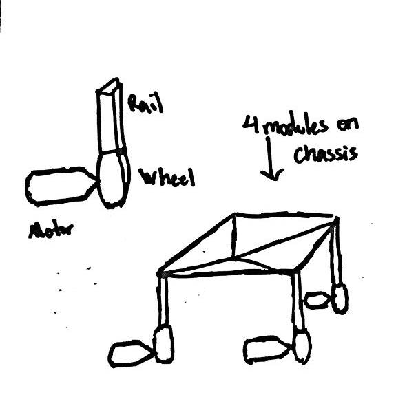
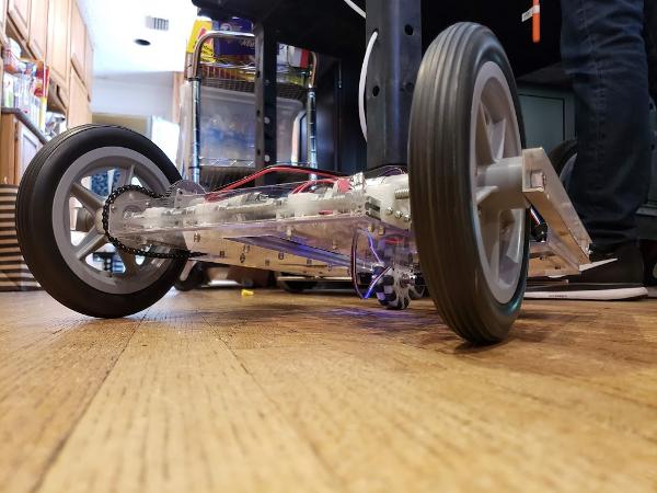
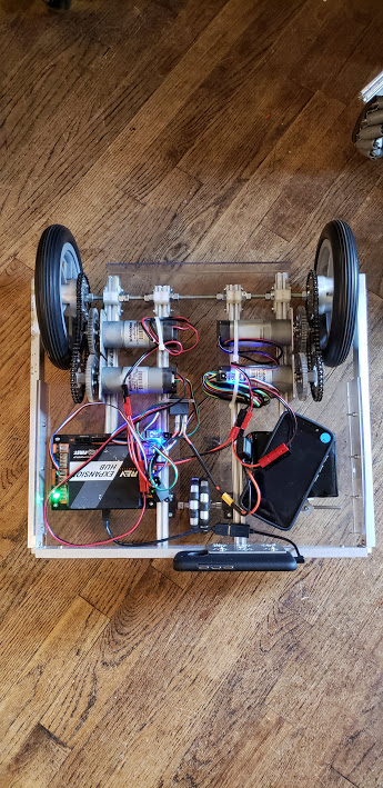
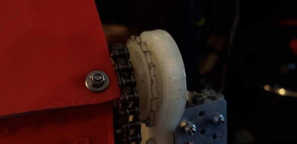
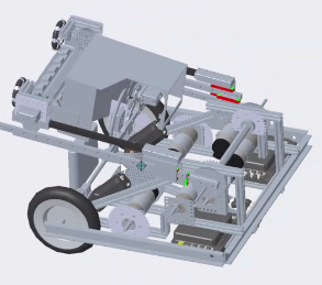
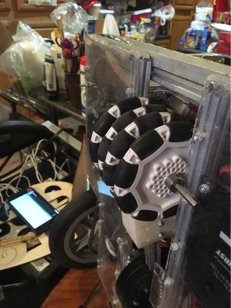
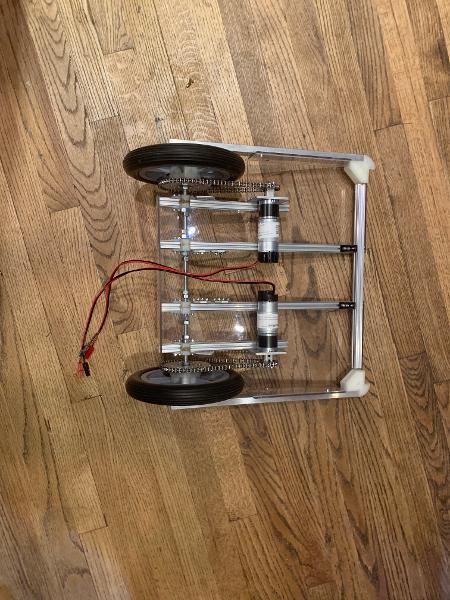
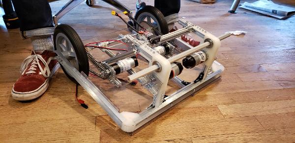
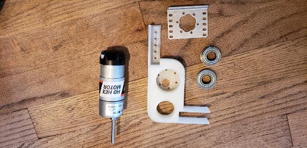
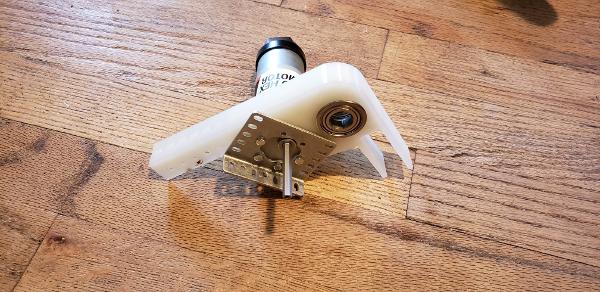
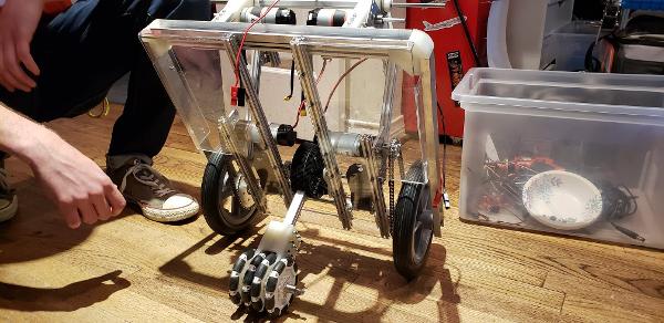
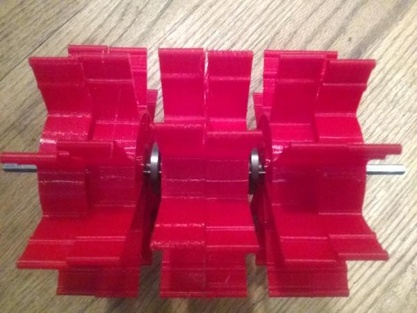
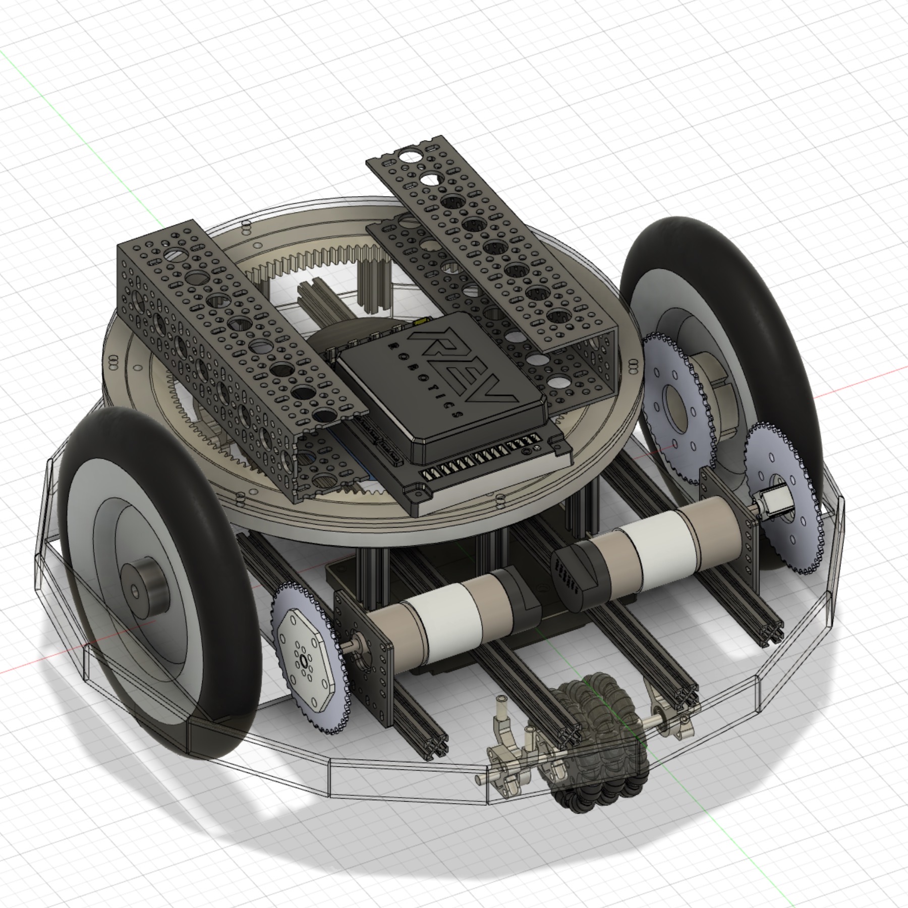
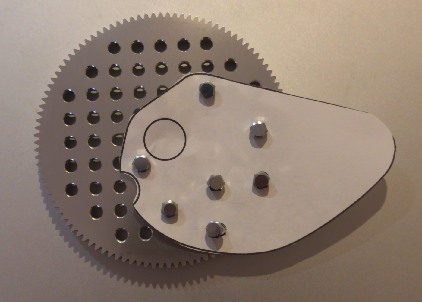
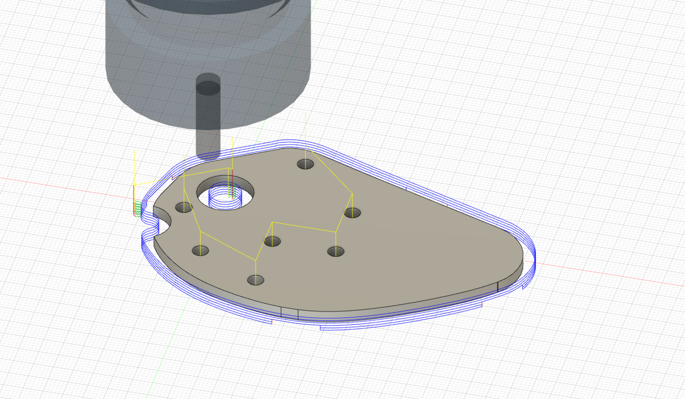
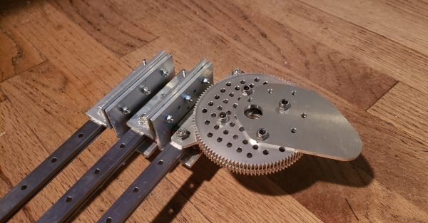
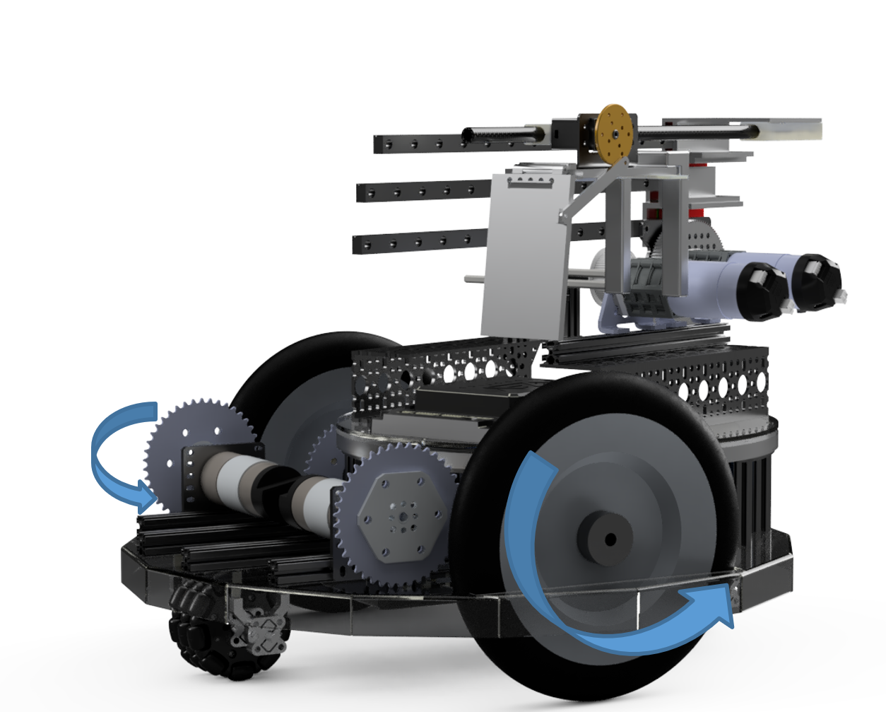
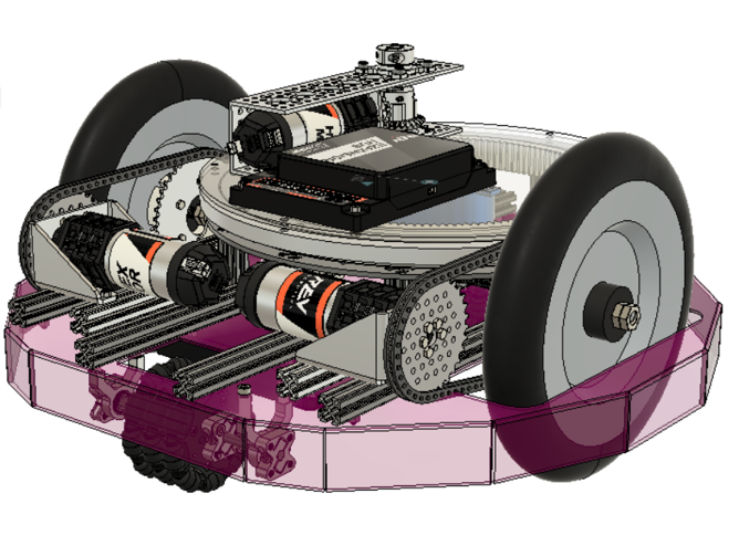
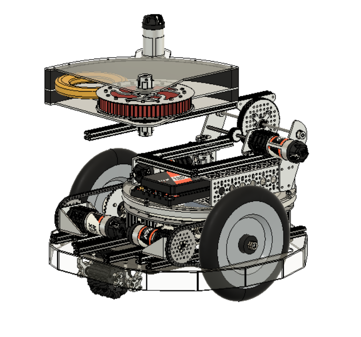
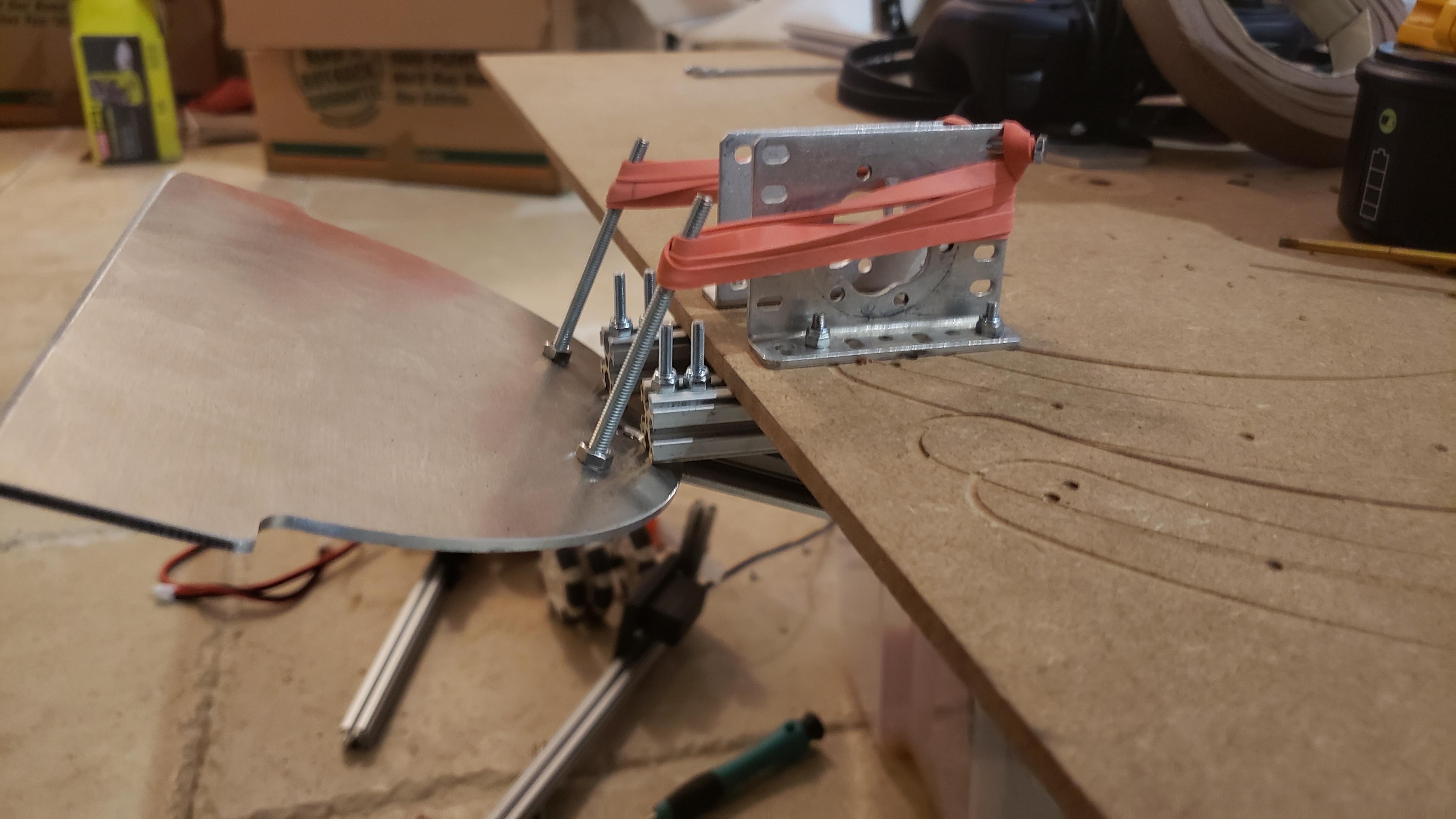
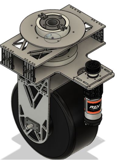
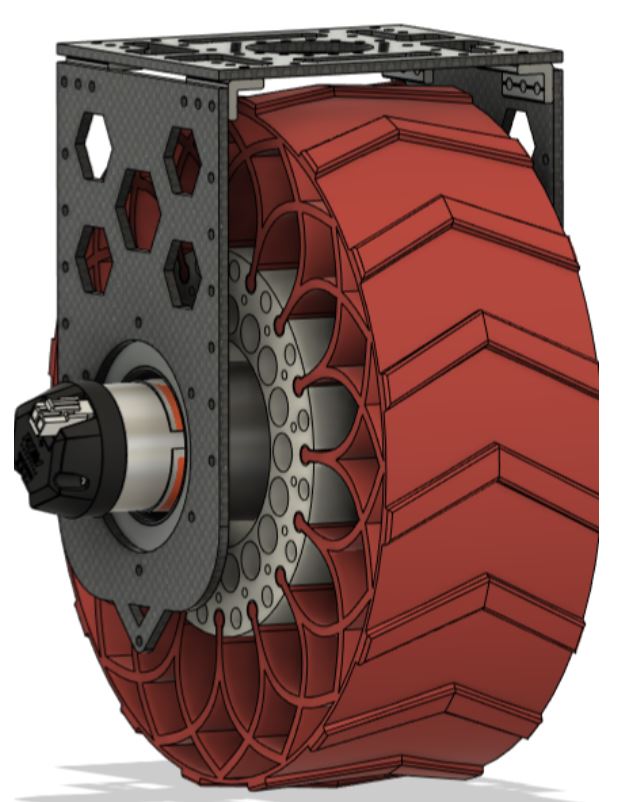
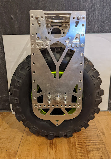
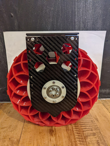
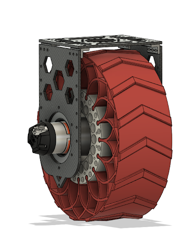
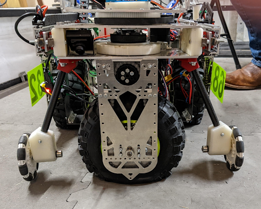
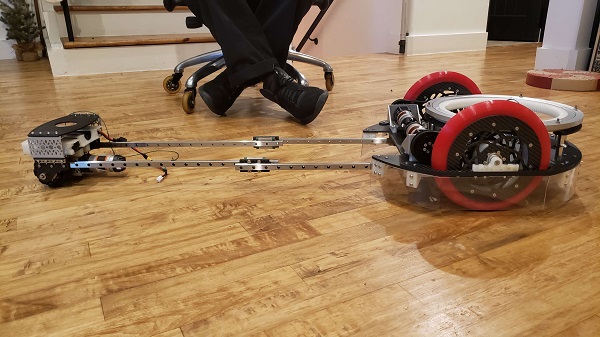
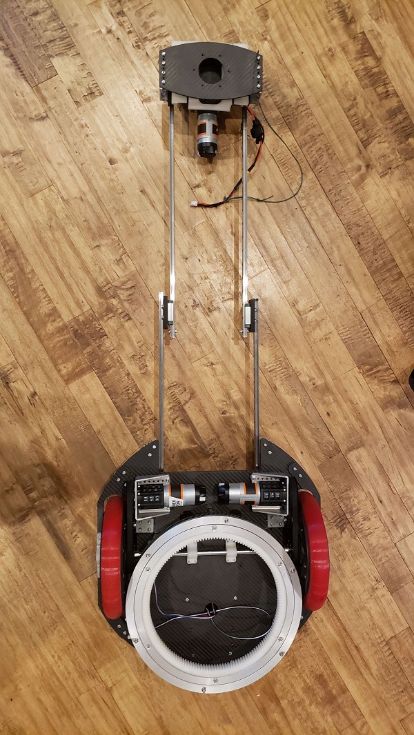
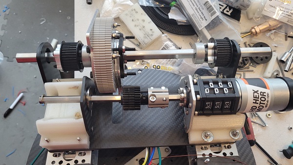
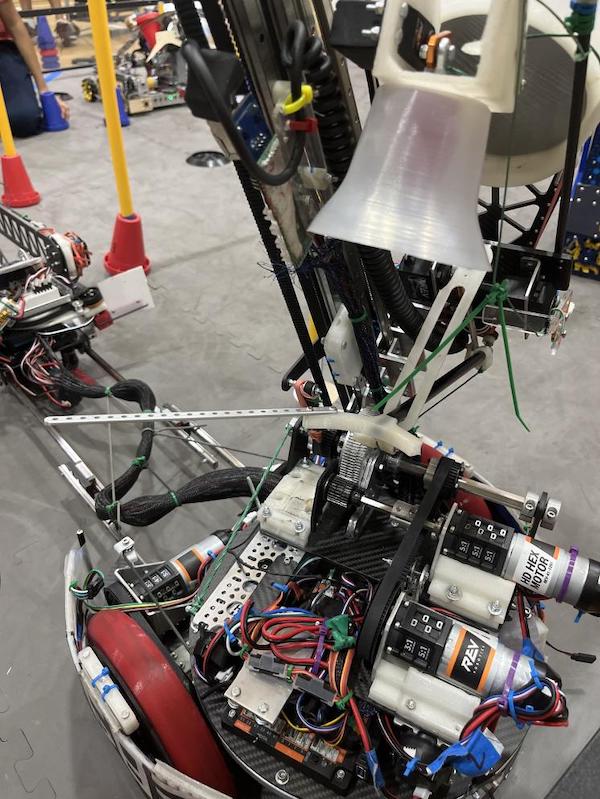
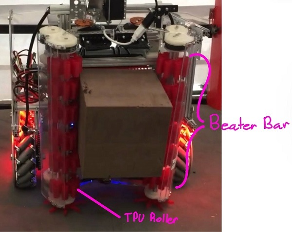
We did this by redesigning our wheel modules and moving the motor further down. Our redesigned wheel modules utilize custom printed "barrier beaters" instead of the rock climbers we used before. These wheels were printed out of ninja flex and nylon and utilized a Gothic Arch design inspired by Monash University's rover wheels. The custom wheel modules used custom carbon-fiber plates and holes in the nylon hub to help reduce weight. Overall, these wheels were excellent at traversing the barriers, weighed less, and the wheel module allowed the motor to drop 5 inches in height. This led to a lower center of mass for the robot.
You can see from these free-body diagrams that as we lower the vertical component of the normal force, the overall rotational torque exerted by the swerve module is decreased, which inspired our decisions to lower the center of mass.
We did this by redesigning our wheel modules and moving the motor further down. Our redesigned wheel modules utilize custom printed "barrier beaters" instead of the rock climbers we used before. These wheels were printed out of ninja flex and nylon and utilized a Gothic Arch design inspired by Monash University's rover wheels. The custom wheel modules used custom carbon-fiber plates and holes in the nylon hub to help reduce weight. Overall, these wheels were excellent at traversing the barriers, weighed less, and the wheel module allowed the motor to drop 5 inches in height. This led to a lower center of mass for the robot.
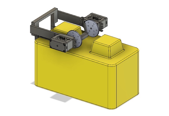
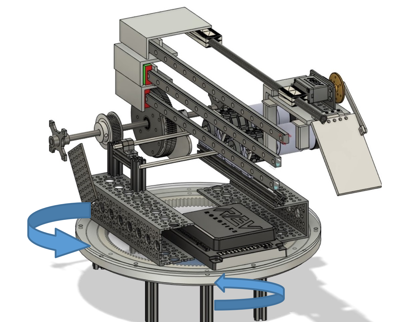
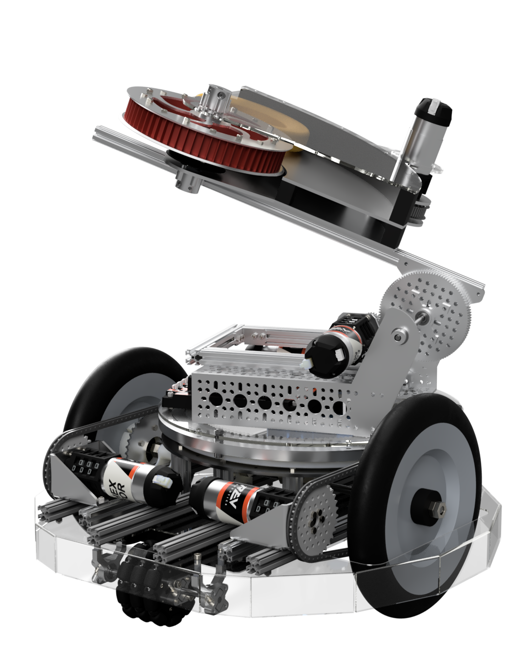
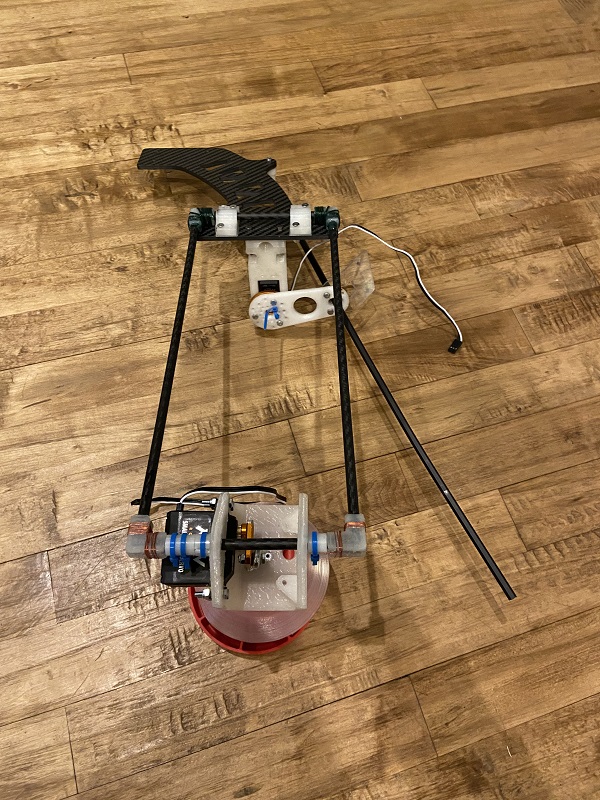
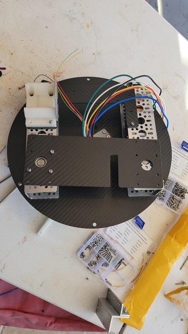
 However, in the situation that the crane and robot extension did lead to the center of mass nearing the base, we installed an outrigger system as a preventative measure. An outrigger is essentially a beam that extends from a robot that is used to improve stability. Our outriggers used omni wheels and functioned similarly to training wheels, preventing the robot from tipping over when the crane moves out and extends.
 Finally, we implemented some code changes to help deal with this problem, building anti-tipping limiters which allowed for gradual acceleration. This prevented the sudden acceleration mentioned earlier which was a cause of our tipping issue. We also programmed in pre-set arm locations to help keep the center of mass near the wheelbase, making sure that the center of mass never passes the base of the actual robot.
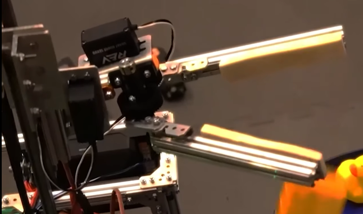
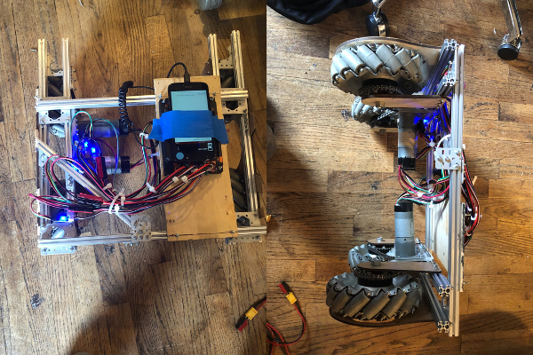
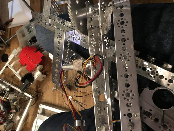
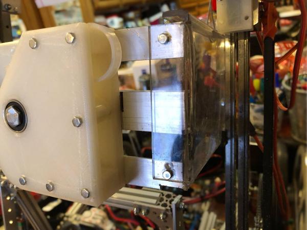
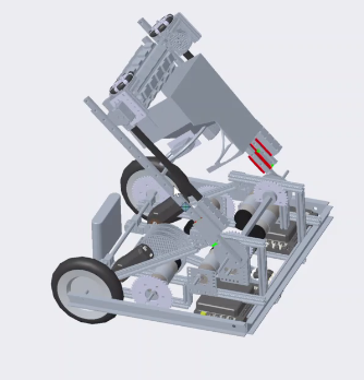
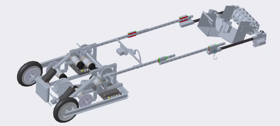
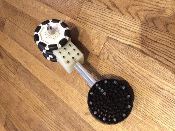
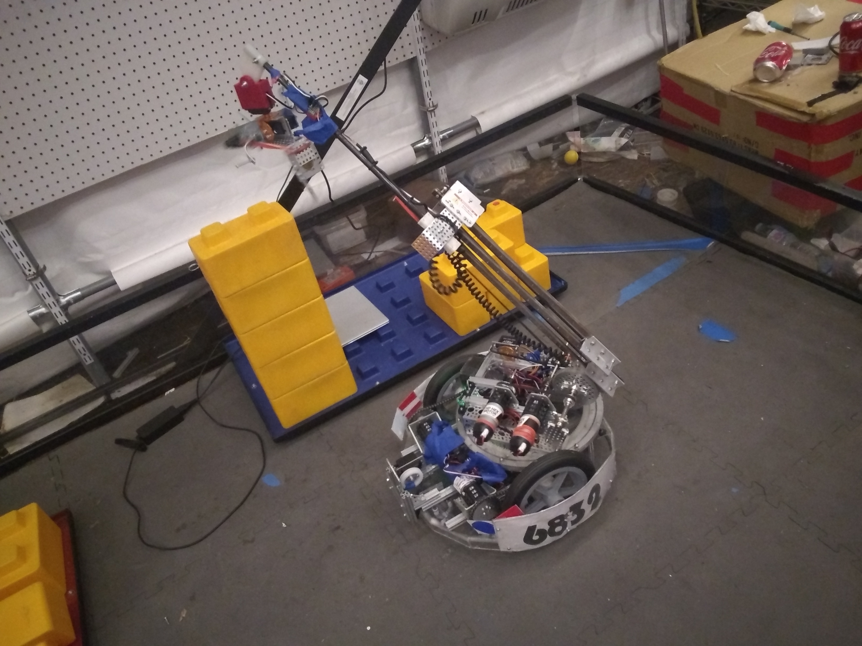
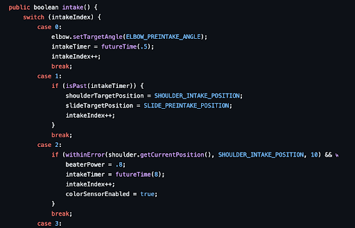 The beginning of our Intake articulation
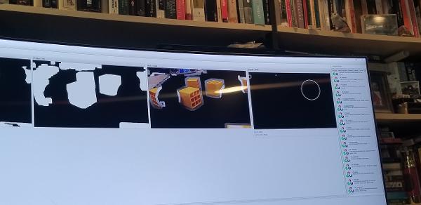
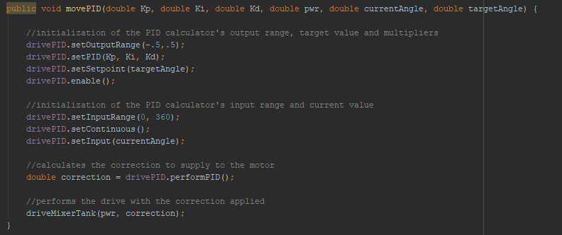
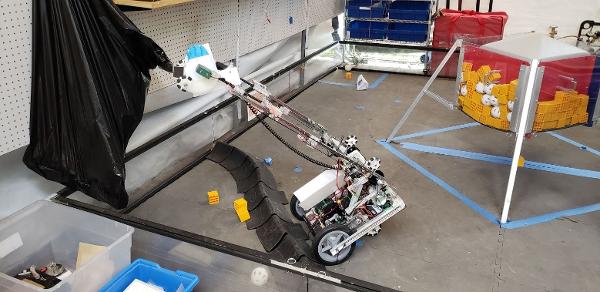
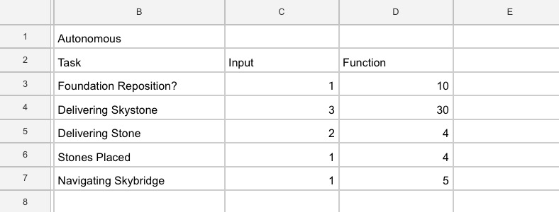
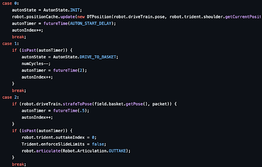 The start of our autonomous state machine